A review of friction stir joining of SiCp/Al composites
Lisheng ZUO,Xinrui ZHAO,Zeyng LI,Dunwen ZUO,*,Hongfeng WANG
a College Mechanical and Electrical Engineering, Nanjing University of Aeronautics and Astronautics, Nanjing 210016, China
b School of Naval Architecture & Ocean Engineering, Jiangsu Maritime Institute, Nanjing 211170, China
KEYWORDS Friction stir joining;Mechanical properties;Microstructure;SiCp/Al composites;Tool wear
Abstract SiCp/Al composites have excellent comprehensive properties and have been widely used in aerospace, automotive industry and other fields. Due to the huge difference in performance between SiC particles and matrix alloys, traditional fusion welding methods are difficult to meet the join requirements of SiCp/Al composites. Friction stir joining (friction stir welding), as a solid phase joining process,has been proved to be a new technology with fine prospect in joining SiCp/Al composites compared with fusion welding process.Although some progress has been made in recent years, there are still full of challenges. In this paper, the research status of friction stir joining of SiCp/Al composites in recent years is expatiated, including the weldability of SiCp/Al composites,the macrostructure and the microstructure of joints,mechanical properties of joints,and tool wear and monitoring.Furthermore,the existing challenges of friction stir joining of SiCp/Al composites are summarized and the future development directions are prospected.
1. Introduction
SiCp/Al composites have excellent comprehensive properties,such as high wear resistance, high corrosion resistance, high specific stiffness and low thermal expansion coefficient.Therefore,the composites have attracted more and more attention in aerospace industry,automobile industry and electronics industry. SiCp/Al composites not only have special applications in various advanced aerospace equipment, such as pelvic fins of fighter, fan outlet guide vanes of aircraft engine, structural materials in satellites, but also can be used as automotive pistons,brake discs,etc.1-4However,the huge difference between the properties of SiC particles and matrix alloys brings great difficulties to the secondary processing of SiCp/Al composites,especially in terms of joining,which has become a major obstacle to its wide application. Conventional fusion welding methods are prone to generate defects such as voids and harmful Al4C3phases formed in the reaction between the SiC particles and the matrix in the molten pool, both of which are difficult to meet the performance requirements of the composite joint.5,6In order to eliminate these defects, it is necessary to avoid melting of the composite material during the joining process. Therefore, solid-state joining seems feasible.
In the solid-state joining process,friction stir joining(FSJ),as a novel solid-phase joining approach, is a revolutionary technique invented in 1991 by The Welding Institute (TWI)in the United Kingdom.7,8In the joining of light alloys, it is favored by aerospace, rail transit, shipbuilding, automobile manufacturing,nuclear industry and other industrial manufacturing fields.It has been widely applied and has broad application prospects.9,10Compared with conventional fusion welding, friction stir joining has many advantages, such as high quality, few defects, small deformation, green cleaning and no pollution in the joining process. Due to the obvious technical advantages,it has been rapidly developed in the field of industrial manufacturing. The materials for joining have gradually expanded from aluminum alloy to magnesium alloy,11copper alloy,12low carbon steel,13stainless steel,14titanium alloy,15polymer16,17and even composite materials.18,19Friction stir joining can also be used to fabricate SiC particle reinforced surface composites20and SiC nanoparticle reinforced welded joints.21This paper attempts to review the existing literature on the friction stir joining of SiCp/Al composites,and also analyze the weldability of the friction stir joining of SiCp/Al composites in detail,focusing on the process parameter, microstructure evolution, mechanical properties and tool wear problems. Finally, the future existing challenges and research directions are prospected.
2. FSJ of SiCp/Al composites
In the friction stir joining of light alloys, process parameters(rotational speed, traverse speed, tool tilt angle and plunge depth etc.) have a significant influence on the performance of joints. In order to obtain great joint performance, it is necessary to match the rotational speed, traverse speed and plunge depth so as to keep the thermal cycle within a certain range.The same is true for SiCp/Al composites and it is important to choose reasonable process parameters.
The friction stir joining of SiCp/Al composites is mainly divided into friction stir lap joining and friction stir butt joining. Song et al.22,23carried out friction stir lap joining of SiCp/Al composite and 2024 aluminum alloy and simulated the temperature field.It was found that defect-free joints could be obtained by choosing appropriate process parameters,which verified the feasibility of friction stir lap joining between SiCp/Al composite and aluminum alloy. SiCp/Al composites have the characteristics of high hardness and low fluidity. A special ‘‘crooked” morphology will be formed at the overlap joint between SiCp/Al composites and aluminum alloys.24As shown in Fig. 1, the SiCp/Al composites under the retreating side have a large interface migration towards the upper aluminum alloy.
The hardness and fluidity of SiCp/Al composites are quite different from ordinary aluminum alloys. In the study of dissimilar friction stir butt joining between SiCp/Al composites and aluminum alloys,the offset of pin is usually used for joining. Xiao et al.25studied the friction stir joining of SiCp/Al composite and 2024Al aluminum alloy by using the pin offsetting and pin without offsetting. The tensile strength of the specimens was tested and the effects of the two schemes on the tensile strength of the specimens were observed.The offset distance of pin has great influence on the welding quality of joints. Reasonable offset distance can improve the joint strength, but the offset distance of pin is often difficult to determine. Cioffi et al.26proposed a novel diagonal joining method, which can effectively find the appropriate lateral offset, as shown in Fig. 2.
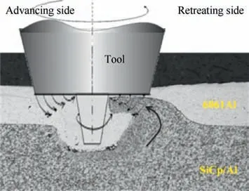
Fig. 1 Schematic diagram of material flow.24
At present, due to the limitation of tools, friction stir butt joining of SiCp/Al composites mainly concentrates on low volume fraction composites. A large number of scholars have indepth studied the feasibility of welding, the optimization of welding process parameters, the mechanical properties and microstructures of joints, tool wear etc.27-67FSJ process parameters of SiCp/Al composites play a key role in the joint quality and the process parameters range is narrower than that of ordinary aluminum alloys. Only when the process parameters are reasonably matched, can the sound joints with excellent mechanical properties be obtained. Table 1 summarizes some FSJ process parameters of SiCp/Al composites, including the content of SiC particles in composites, the thickness of plates, the material and shape of tools and the process parameters. The process parameters listed in Table 1 are research parameters, not the parameters of defect-free joints.It can also be seen from Table 1 that SiCp/Al composites can be successfully joined by friction stir joining and the process parameters window range is small.
3. Macrostructure and microstructure of FSJ joints
3.1. Macrostructure of FSJ joints
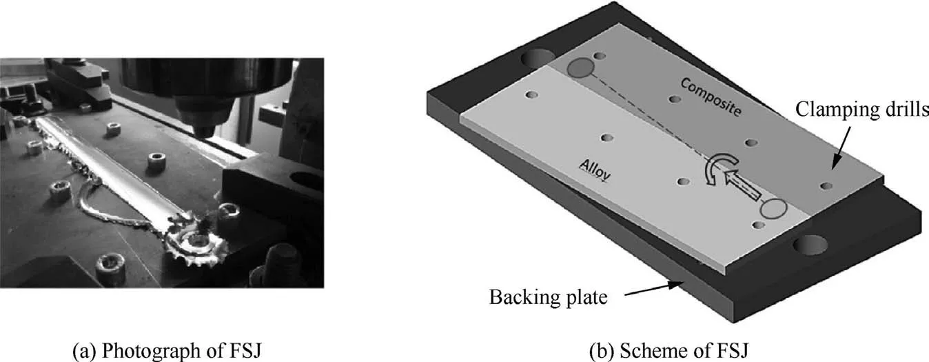
Fig. 2 Diagonal friction stir joining experiments and scheme.26
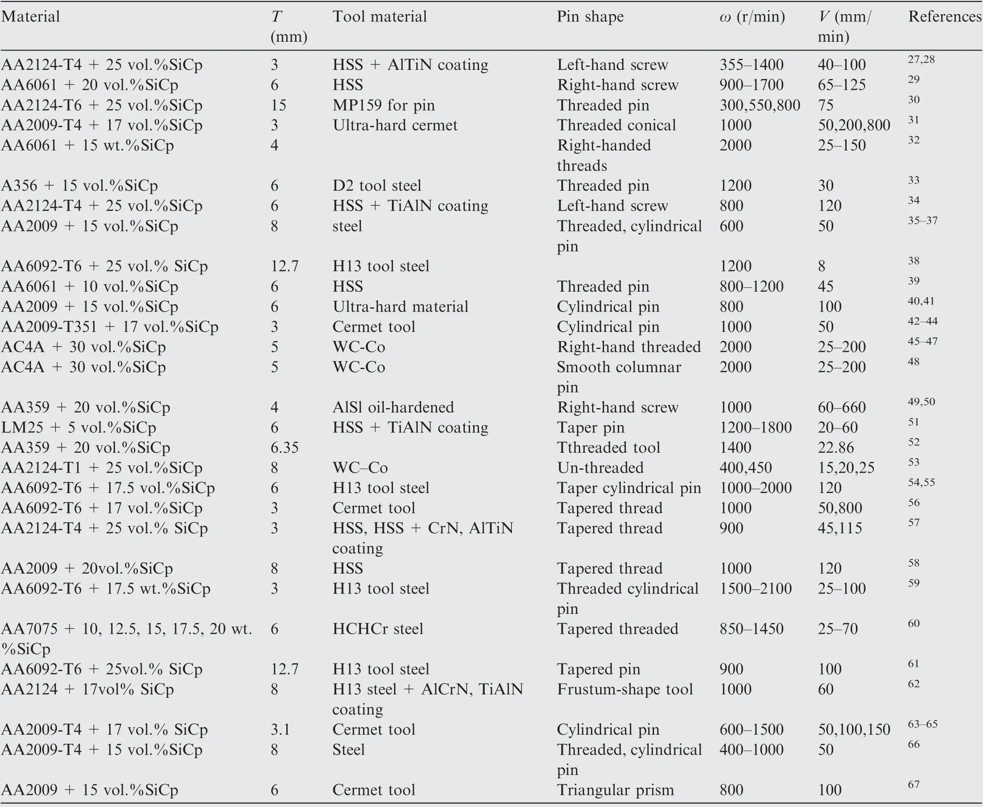
Table 1 FSJ process parameters of SiCp/Al composites.
The FSJ joints of SiCp/Al composites are similar to aluminum alloy joints and can be divided into nugget zone(NZ),thermomechanical affected zone (TMAZ) and heat affected zone(HAZ). Whether there are weld defects such as tunnels or voids on the cross section of the joints is closely related to the heat input.39,55Since the SiCp/Al composite contains reinforced phase SiC particles, the material has low fluidity, so higher heat input welding parameters are required to obtain a defect-free welded joint.68Furthermore,lower heat input will lead to insufficient plasticization of the metal around the pin and inhibit the flow of material. On the contrary, higher heat input can cause excessive plasticization of the metal and turbulence of the metal material around the pin.Only when there is a suitable heat input, can the metal material be plasticized fully,can the material around the pin flow freely,and the joint with great joint performance be produced. Ma et al.66found that the heat input of friction stir joining had a great influence on the weldability of joints. The results revealed that defects appeared in the nugget zone of the joints at low heat input(400 r/min) during the FSJ of SiCp/Al composites. With the increase of rotational speed, that is, when the heat input increased, the defects disappeared and a defect-free joint was obtained. The cross section of the joints was shown in Fig. 3. Similarly, Periyasamy et al.39studied the effect of heat input (different rotational speed) on friction stir joining of composites and found semblable results. Some void defects were observed in the joints when the heat input was either too low (755, 850, 945 J·mm-1) or too high (1133 J·mm-1).Moreover,a defect-free joint was obtained when the heat input was 1039 J·mm-1. Cioffi et al.30also reported that tunnel defects appeared in the joints at low speed of 300 r/min.When the speed increased to 800 r/min, the defect-free joints were produced. Higher rotational speed generates more energy input,which makes the material flow sufficiently so as to avoid tunnel defects.
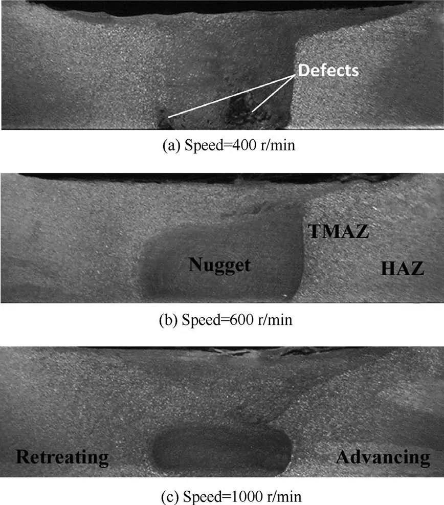
Fig. 3 Cross section of the joints.66
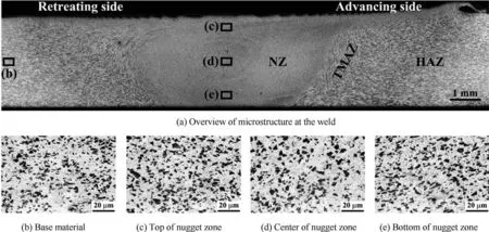
Fig. 4 Optical images of FSJ sample.64
3.2. Change of SiC particles
As shown in Fig.4(a),the nugget zone is elliptical and the typical onion ring structure is visible clearly. Fig. 4(b)-(e) show the distribution of SiC particles in different regions. It can be seen that the distribution of SiC particles in the nugget zone is more uniform than that in the base material (BM).64
In the SiCp/Al composite, the reinforced particles are nonuniformly distributed in the matrix and exist in the form of particle clusters, which will affect the mechanical properties of SiCp/Al composites.In the friction stir joining,due to the friction and agitation of the tool,the composite material undergoes severe plastic deformation.The SiC particles in the nugget zone flow and rotate in the matrix under the driving of the pin.Additionally,some clusters of SiC particles are destroyed and rearranged. The redistribution of SiC particles is more uniform than that of matrix materials,which is consistent with previous research results.28,30,33-35,38,40-44,48,49,55,56,59,61,63,66Meanwhile,the severe stirring of the pin exacerbates the friction and wear between the reinforced particles and the pin and causes a damaging effect on the SiC particles.In contrast with the sharp SiC particles in the matrix,the edge angle of SiC particles in nugget zone becomes blunt obviously and some coarse SiC particles even crack, as shown in Fig. 5. Similar phenomena have been observed in other studies.33,35,41,59,61
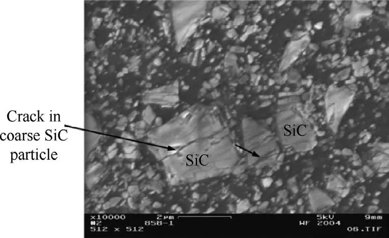
Fig. 5 Crack of coarse SiC particles.34
During the friction stir joining, the size and aspect ratio of SiC particles will decrease significantly. The literature35reported that the average size of SiC particles in the weld nugget region decreased from 5.4 μm to 4.2 μm after friction stir joining.The variation trend of SiC particle size in nugget zone can be analyzed by particle size statistics.Fig.6 shows the SiC particle size distribution of base material and welding zone(NZ and TMAZ) at different rotational speeds. The finer SiC particles (less than 8 μm) in the microstructures of NZ and TMAZ are more numerous than that in BM. With the increase of rotational speed from 1000 r/min to 1500 r/min, it is found that the number of fine particles increases gradually.Under the same rotational speed,it can also be seen that there are more and finer particles in NZ than in TMAZ. However,the change trend of SiC particle size at 2000 r/min is opposite,probably because the material becomes more plastic at high rotational speeds (2000 r/min) due to more heat input. The tool slides smoothly in the material and the force required to break the SiC particles cannot be generated on the SiC particles.
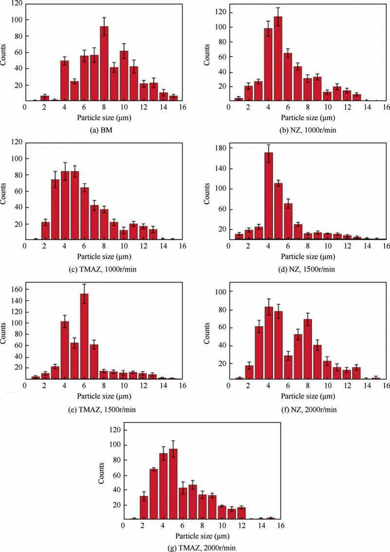
Fig. 6 Particle size distribution in BM, NZ and TMAZ at different rotational speed.55
3.3. Recrystallization behavior in NZ
After the friction and stirring of the tool, the SiC particle size in the nugget zone is significantly smaller,but the recrystallization of the matrix material can not be inhibited.35Moreover,the ideal temperature of the friction stir joining is about 0.8 times as high as the melting point of the material,which causes grain refinement, recrystallization and growth of the SiCp/Al composite in the nugget zone.69Therefore, there are sufficient conditions for recrystallization of the composite material in the NZ. In friction stir joining, due to the dynamic recrystallization process,new equiaxed grains in NZ are much smaller than those in BM.35,41Fig. 7 shows the electron backscattered diffraction(EBSD) results for the BM and joints.59Black represents high angle grain boundaries (HAGBs), red represents low angle grain boundaries(LAGBs)and the white region represents reinforced particles.With the increase of welding speed,LAGBs increase gradually. The microstructural differences of joints with varied parameters are mainly related to temperature changes.Fig. 8 shows the relationship between peak temperature and average grain size in NZ. With the increase of welding speed, it can be seen that larger grains can be formed in the nugget zone. With the increase of welding speed, the heat input decreases, the plastic deformation is insufficient and the cooling rate increases, which will lead to incomplete recrystallization in NZ to form coarse grains. The increase of rotation speed can coarsen the microstructures, which is consistent with the previous studies.39With the increase of welding temperature, the microstructures become coarser.

Fig. 7 EBSD results of BM and joints.59
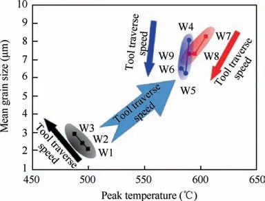
Fig. 8 Relationship between mean grain size and peak temperature.59
In addition,the cracked SiC particles also affect the recrystallization behavior. During the welding process, the new surface of the cracked SiC particles contacts directly with the matrix. Therefore, the matrix is prone to nucleate on the SiC particles and form a crystallization orientation relationship to reduce the free energy of the interface.41
3.4. Interfacial behaviors of SiC particle-Al matrix
Fig. 9(a) showed transmission electron microscopy (TEM)images of interfacial compounds between SiC and Al matrix in the NZ of FSJ samples and some compound particles (as shown in ‘‘E”) in the matrix around SiC particles were observed. Wang et al.41found that the composition of these compound particles was different from that of the compound particles around the SiC particles in the matrix by energy dispersive spectroscopy (EDS) analysis. In the FSW process, the compound particles on the interface of Al matrix in the NZ were directly contacted with the pin, and these compounds were destroyed and dispersed into the matrix with the stirring action of the tool. Fig. 9(b) showed that the interface around some fine SiC particles in FSW samples was relatively clean.The fine particles were formed by the sharp corners of broken SiC particles with the stirring and wearing of the pin. In the FSJ process,the peak temperature of NZ is significantly lower than the thermal consolidated temperature and the duration is very short.It is unlikely that a compound form on the new surface of the broken SiC particles. Therefore, the interface around the refined SiC particles after FSJ is very clean.
Feng et al.37found that there were some black compound particles around SiC particles in the nugget zone of FSJ specimens and FSJ-T4 specimens,and there was no interface transition layer between SiC particles and the compound particles.EDS analysis showed that the composition of the compound was very close to that of Cu2FeAl7phase. The results showed that the T4 heat treatment did not change the Cu2FeAl7phase in the SiCp/2009Al composite joint because the dissolution temperature of the Cu2FeAl7phase was much higher than the solution treatment temperature.
3.5. Evolution of precipitates
The FSJ of SiCp/Al composites is the same as that of aluminum alloys. The precipitates in the weld will dissolve and re-precipitate due to plastic deformation and heat effect, and the evolution behavior of these precipitates will affect the properties of the joint. In the FSJ process of SiCp/AA2009-T351,44due to thermal cycling, the precipitates dissolved into the Al matrix. During the cooling process, some precipitates dissolved in the NZ re-precipitated and transformed into θ(Al2Cu)phase.In addition,S(Al2CuMg)and θ(Al2Cu)phases were formed in HAZ. Wang et al.40studied the evolution of Al2Cu phase in the FSJ of SiCp/2009 Al composites. From the X-ray diffraction (XRD) curve in Fig. 10, it can be seen that the Al2Cu peak in NZ of FSJ specimen was significantly less than that in BM, which indicated that most of the Al2Cu particles were broken and dissolved in the matrix after strong plastic deformation and thermal cycling. However, due to the short welding time, some of dissolved Al2Cu phases reprecipitated during the cooling process, and finally some of the Al2Cu phases were retained in the NZ. XRD results showed that there were few Al2Cu phase peaks in the FSJ-T4 sample (Fig. 10), indicating that most of the Al2Cu phase dissolved in the matrix after solution treatment.
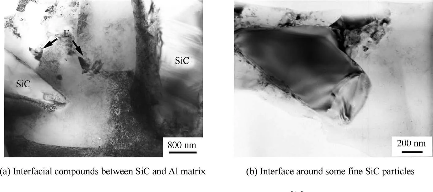
Fig. 9 TEM images of interface.41

Fig. 10 XRD profiles of SiCp/2009Al composite.40
4. Mechanical properties of FSJ joints
4.1. Tensile property
There are many factors affecting the strength of FSJ joints of SiCp/Al composites.The main factors depend on the choice of process parameters. In order to obtain a joint with excellent performance, it is necessary to optimize the process parameters. Periyasamy et al.29and Devanathan et al.51experimentally studied the relationship between the FSJ process parameters of SiCp/Al composites and the properties of joints,and finally obtained the optimal combination of process parameters. The process parameters also can be optimized by establishing a regression model60or by establishing a relationship between process parameters and joint tensile properties with the decision tree algorithm.27Table 2 summarizes the tensile properties of FSJ joint of SiCp/Al composites and lists the optimum process parameters corresponding to the tensile properties. It can be seen that the ultimate tensile strength(UTS)of the joints can reach 70%-97%of the matrix material.

Table 2 Tensile properties of FSJ joint of SiCp/Al composites.
In the FSJ process, the process parameters directly affect the heat input which has a great influence on the tensile properties of the joints. Therefore, the optimal process parameters can produce the joint with best performance. Uttam et al.55studied UTS of three kinds of joints with different rotational speeds(1000 r/min,1500 r/min and 2000 r/min)and found that the UTS value at 1500 r/min was the highest, reaching 347 MPa. With the increase of rotational speed, UTS of joint is reduced at 2000 r/min.Further analysis showed that samples of 1500 r/min had more and smaller grains,and the fine grains increased the strength of the joint. The change of grain size is related to heat input. In addition, the corresponding relationship between UTS and total energy input (Htot) is shown in Fig.11.From the joints of W3,W6 and W7,it can be seen that UTS increases with the increase of Htot. This finding is very similar to that of Periyasamy et al.41As for the joints of W7 and W8, UTS decreases with the increase of Htotbecause of the serious overaging of the matrix alloy.
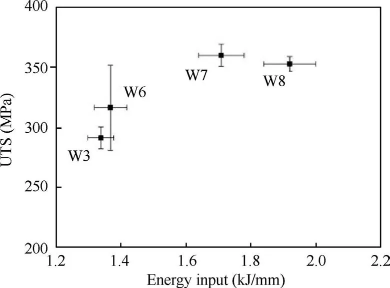
Fig. 11 Relationship between UTS and energy input.53
The effect of rotational speed on the tensile strength of joints has been generally accepted,but there are different opinions about the effect of traverse speed on the tensile strength of joints.Wang et al.31carried out friction stir joining on SiCp/Al composites at different traverse speeds (50 mm/min, 200 mm/min and 800 mm/min). It is found that the UTS of the joint increases with the increase of traverse speed at 1000 r/min of rotational speed, reaching 97% of the strength of the base material at 800 mm/min. Similar results46show that UTS increases slightly with the increase of traverse speed. When the traverse speed is 150 mm/min, the UTS of the joints reaches its maximum value of 140 MPa. However, UTS does not always increase with the increase of traverse speed. Bozkurt et al.27found the opposite result,which is UTS decreased gradually with the increase of traverse speed at a constant rotational speed. Generally speaking, the increase and decrease of welding speed directly affect heat input and cooling rate of joints. Higher welding speed results in faster cooling rate,lower heat input and lower degree of microstructural transformation, which reduces the tensile strength of joints. Lower welding speed increases heat input and slows down cooling rate, which makes the substrate overage and reduces the strength of the joint.
Besides,the selection of FSJ process parameters of SiCp/Al composites takes into account the wear of SiC particles on tools. When the parameters exceed the critical value, the tool wear will be aggravated.The tool wear will leave the tool material (such as iron and debris) in the nugget zone, causing the bad performance of the joints.54,55The residual iron will react with other elements in the matrix. Feng et al.37analyzed that the formation of Cu2FeAl7phase in FSJ of SiCp/Al-Cu-Mg composites. It was probably due to the solid-state reaction between Fe, CuAl2and Al under severe plastic deformation and high temperatures. The Cu2FeAl7phase reduced the mechanical properties of the joint. Firstly, the formation of Cu2FeAl7particles at the interface of SiC particles may reduce the interfacial bonding between SiC and Al matrix. Secondly,the formation of Cu2FeAl7phase reduced the precipitation strengthening effect.37
4.2. Microhardness
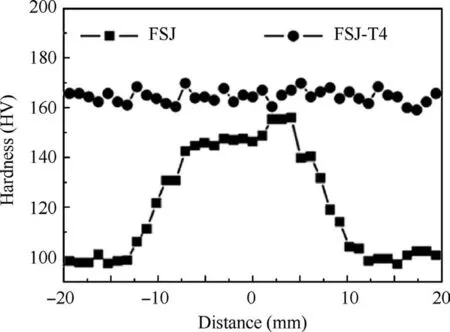
Fig. 12 Hardness profiles of different conditions.40
The hardness distribution of FSJ joints of SiCp/Al composites generally has two forms, one of which is a typical ‘‘W”shape,28,31,34,42-44,56,59and the other is similar to inverted‘‘V” shape.33,35,39,40,46,48-50,61,66The hardness distribution is closely related to the heat treatment state of the composites.In the FSJ of SiCp/Al composites, the microhardness at the joint changes due to the thermal cycling and the stir of the pin. The partial dissolution and reprecipitation of precipitates in the nugget zone will result in a significant increase in the hardness. Meanwhile, the welding nugget zone is stirred strongly by tool and a large number of dislocations are formed at grain boundaries,resulting in strain hardening.In addition,the fracture and uniform distribution of SiC particles in the weld nugget zone and the refinement of the matrix grains also increase the microhardness.According to Hall-Petch equation,the micro-hardness increases with the decrease of grain size.35The thermal cycling effect of the HAZ is lower than that of the NZ,so the precipitate phase and the grain size coarsens under thermal action, and the dislocation density decreases, which is the cause of HAZ weakening.
The heat treatment state of the joint has a great influence on the distribution of microhardness.Fig.12 showed the hardness distribution of the FSJ and FSJ-T4 samples on the cross section of the joint. For the FSJ sample, the hardness value of the NZ is the highest, and the hardness decreases gradually as the distance to the NZ increases.In addition,the advancing side of the NZ has a higher hardness value than the retreating side.After T4 treatment,the hardness of each part of the joint reaches about 170 HV, and the distribution is relatively uniform. Similar results were found in literature.35During the FSJ process, the NZ of the joint undergoes strong plastic deformation and thermal cycling. Some coarse precipitates Al2Cu are broken and dissolved, the SiC particles are broken and the grain is refined, which leads to a significant increase in the hardness of NZ. After T4 treatment, all precipitates Al2Cu in each zone of the joint are basically dissolved in the matrix,and the precipitation strengthening effect in each zone of the joint is similar, so the hardness distribution is uniform.
4.3. Fatigue property
The fatigue failure of welded structural parts is usually easy to occur at the joints under the service conditions of alternating loads. Therefore, the fatigue characteristics of FSJ joints are critical to the overall performance of the structural parts.The fatigue properties of FSJ joints are mainly affected by factors such as microstructure,residual stress and internal defects.Salih et al.59considered that the fatigue behavior of joints mainly depended on the evolution of microstructures and the range of cyclic strain. The relationship between fatigue life and grain size under different strain ranges was studied and the trend of fatigue life at low speed (1500 r/min) and high speed (1800 and 2100 r/min) was explained. The high cycle fatigue behavior of FSJ specimens of 17%SiCp/AA2009 composites was studied by Ni et al.42It has been found that the fatigue life of BM was longer than that of FSW joint at higher stress amplitude. However, the fatigue life of BM and FSW samples was the same in general at low stress amplitude. It was analyzed that the residual stress existing in the joint affected the fatigue behavior of the FSJ joint.The compressive residual stress was beneficial to the fatigue behavior and might play a great role under the low stress amplitude.Therefore,the interaction of external loads and residual stresses resulted in an increase in the fatigue life of the FSW joint. In addition, the ductility of FSJ joint was better than that of BM, which can release stress concentration effectively. Wang et al.56studied the fatigue behavior of SiCp/6092Al composite FSJ joints and found that the surface morphology of joints has a great influence on the fatigue limit. Compared with the unpolished sample, the fatigue limit of polished sample was increased by 40-65 MPa,and the S-N curve of the polished sample is shown in Fig. 13. The main reason for the difference of fatigue limit between unpolished and polished specimens was that fatigue cracks were initiated easily at the root of the dent of the unpolished surface.
4.4. Residual stress
In the FSJ of SiCp/Al composites, thermal cycling and severe plastic deformation will lead to residual stress in the joints.Residual stress will affect the initiation and propagation of fatigue cracks directly and have a great impact on the fatigue life of joints. There are many methods to measure residual stress,such as hole drilling method,synchrotron X-ray diffraction,X-ray diffraction and neutron diffraction.These methods can be used to estimate the residual stress distribution of FSJ samples.Ni et al.42studied the distribution of residual stress in the FSJ joint of composites using X-ray diffraction.The results indicate a tensile residual stress in the center of the weld and a compressive residual stress in the base material.Residual stress decreases dramatically from the center line to both sides(advancing side and retreating side). Residual stress decreases to-70 MPa in HAZ on advancing side and-60 MPa in HAZ on retreating side.Zhang et al.63-65measured the macroscopic and microscopic residual stresses of composite joints by neutron diffraction and developed an enhanced multi-scale model to predict the residual stress.The predicted values were in good agreement with the neutron diffraction measurements. Fig. 14 showed the distribution of macroscopic residual stresses in the three directions of transversal(T),normal(N)and longitudinal(L) at different traverse speeds. It can be seen from the figure that the residual stress varied greatly in the L direction, showing tensile residual stress in the weld center and the heat affected zone, but exhibiting compressive residual stress in the substrate. The maximum Macro-tensile residual stress in L direction usually occurs near the shoulder edge. Because of high heat input, the area of Macro-tensile residual stress in L direction will be wider.
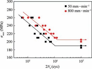
Fig. 13 S-N curves for polished specimens.56

Fig. 14 Profiles of L (a), T (b) and N (c) macroscopic residual stress cross welds for V50, V100 and V150.65
5. Tool wear and monitoring
Although FSJ has been applied to the connection of nonferrous metals and achieves good results, there are still some challenges in the connection of SiCp/Al composites. The reinforcing phase of SiC particles can cause severe wear on the tools.47,49,50,52-54,57,58,62When the tool is worn severely, the defect-free welded joint can not be obtained and the tool life is reduced greatly. Moreover, tool wear debris can also contaminate the weld seam and reduce the mechanical properties and stability of the joint.As the‘‘heart”of friction stir joining,the tool is essential to determine the welding quality of SiCp/Al composites.
The tool wear has a certain relationship with the process parameters of the friction stir joining. Prater et al.70extracted tool wear data during friction stir welding of Al359+20%SiCp composites and derived a dimensionless parameter that could be used to evaluate the tool wear according to the three main variables of rotational speed,traverse speed and welding length. Previous studies have found that tool wear is proportional to rotational speed and welding length, and inversely proportional to welding speed.47,49,58Fig. 15 shows the wear state of the tool after each welding.58With the increase of welding times, the threads on the tool disappear gradually. It is also found that the maximum wear of the pin occurs in the middle part, which is due to the evolution of selfoptimization of the tool in friction stirring joining.49Similar results were found by Ferna´ndez et al.50It is also found that there is a linear relationship between the wear rate and rotational speed, and the initial wear of the tool can be delayed by the decrease of the rotational speed and the increase of the traverse speed.
Generally speaking, these results show that tool wear can be reduced by controlling process parameters,such as reducing rotational speed and increasing traverse speed. However, the premise of controlling the process parameters is to ensure the quality of the joints. It is not necessary to degrade the performance of the joints for reducing tool wear.Therefore,in order to reduce the tool wear during the friction stir joining of the SiCp/Al composites, some researchers have tried to use some hard materials to make tool, such as MP159, ultra-hard coating, ultra-hard material, cermet tool, WC-Co, WC+Diamond coating, etc. Wang et al.40welded 15 vol.%SiCp/2009Al successfully by friction stir joining with the tool made of ultra-hard materials, and the tool did not have obvious wear during the welding process. Ni et al.44welded AA2009+17%SiCp composites of 3 mm thickness with ceramic tool and found there is no visible wear on the tool. Devanathan et al.51used a TiAlN coated tool to perform friction stir joining of LM25+5% SiCp composites and found that the coated tool did not undergo significant wear.It can be concluded that the wear of tools was acceptable for SiCp/Al composites with low volume fraction (less than 17%) by using some ultra-hard tools for friction stir joining.
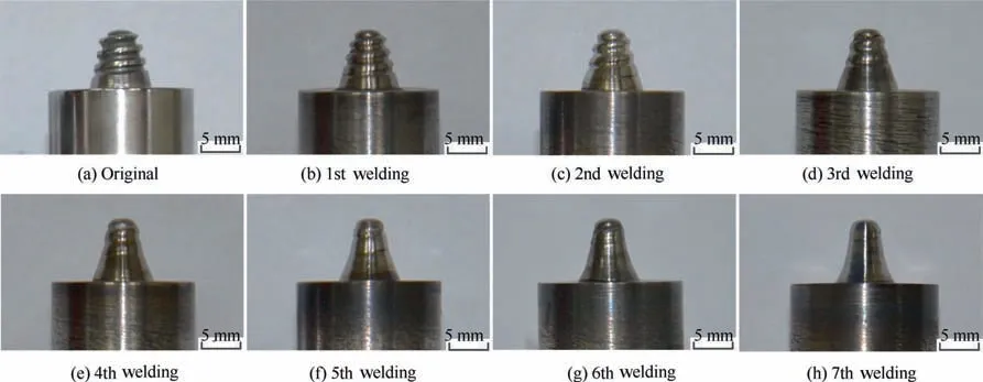
Fig. 15 Wear state of the tool.58
However,in terms of SiCp/Al composites with high volume fraction, tool wear can not be avoided completely even with cermet tools.Liu et al.47used a WC-Co cemented carbide tool to weld 30 vol.% SiCp/AC4A composites and found that the wear rate of the tool increased as the welding speed decreased.Prater et al.71observed wear of tool with different materials(O1 steel, micron cemented carbide, submicron cemented carbide and diamond coating) in friction stir joining of Al359+20%SiCp and Al359+30%SiCp composites.It was found that the wear resistance of the WC-Co tool was much better than that of the O1 steel, but the wear still occurred. The diamond coating tool had a certain effect on the wear resistance.Although the diamond coated tools have some advantages,there are still many challenges to face. Firstly, the bond strength between coating and matrix can not be well-solved.Secondly, when the coatings on the tool surface wear or peel off, the tool will return to the level of the matrix material and wear rapidly.
In the friction stir joining process of SiCp/Al composite materials, it seems necessary to monitor the tool in real time,so that the wear state of the tool can be monitored and the tool can be replaced in time to avoid welding failure. Besides, tool monitoring can collect torque signal or acoustic emission signals online to evaluate wear status.52,58The research shows that there is a correlation between the attenuation of the torque signal and the volume of tool wear. The radial wear of the tool corresponds to the decrease of the torque. The attenuation of the torque signal provides a new method for monitoring and controlling tool wear in joining process. There is also a corresponding relationship between acoustic emission signal in friction stir joining of SiCp/Al composites and wear state of tool. The worse the wear is, the larger the root mean square value of the acoustic emission signal is. Additionally,the energy of the acoustic emission signal moves gradually toward the low frequency region. The analysis of acoustic emission signals also provides a new method for on-line wear monitoring of friction stir joining.
6. Summary and outlooks
SiCp/Al composites have outstanding properties and great development potential, but the difficulties in joining have become one of the bottlenecks restricting their engineering application. As a solid-phase joining technique, FSJ can overcome the problems of voids, excessive eutectic,hot cracks and formation of harmful phase Al4C3in the fusion welding process. Furthermore, the join of the SiCp/Al composites can be performed successfully and a defect-free joint with good performance can be obtained. In the review, the friction stir joining of SiCp/Al composites is analyzed and the process parameters,microstructure,mechanical properties and the tool wear are discussed. The process parameters of the friction stir joining (rotational speed, traverse speed, etc.), material and shape of tool can determine the microstructure and mechanical properties of the joint. Unreasonable selection of process parameters and tools will directly lead to insufficient or excessive heat input and tunnel defects will be easily formed at the joints, which will have a profound impact on the distribution of SiC particles and grain refinement. Therefore, the optimal selection of process parameters, materials and shapes of tool is of vital importance.
At present, the main problem of friction stir joining of SiCp/Al composites is tool wear.For low volume fraction(less than 17%) SiCp/Al composites, defect-free joints can be obtained with conventional tools such as cermet, WC-Co and hard coating, and tool wear is acceptable. However, for high volume fraction SiCp/Al composites, it is still essential to find more wear resistant and high temperature resistant tool materials with sufficient hardness and toughness. In addition to tool wear, how to improve the performance of SiCp/Al composite joints is also a problem that needs to be solved at present. If we can solve these problems, it will bring huge opportunities for the industrial application of friction stir joining of SiCp/Al composites.
For the development of friction stir joining of SiCp/Al composites,there are three main research focuses in the future.Firstly,the wear problem of tools is effectively solved.The tool materials (such as PCBN, PCD, W-Re alloy, etc.) with high temperature and wear resistance are to be studied in depth and a reliable tool material is urgent to be developed. Secondly, it is important to monitor the wear state of tool in real time and to predict the tool life effectively by combining the theoretical and numerical simulation of the interaction between SiCp/Al composites and tools.Finally,the interaction mechanism among process parameters, tool wear, microstructures and mechanical properties of SiCp/Al composite FSJ needs to be studied deeply, and the joint performance can be predicted effectively and controlled accurately by optimizing process parameters.
Acknowledgements
This work was supported by the National Natural Science Foundation of China (No. 51675270); the Postgraduate Research & Practice Innovation Program of Jiangsu Province(No. KYCX17_0241) and the China Postdoctoral Science Foundation (No. 2016M600411).
 CHINESE JOURNAL OF AERONAUTICS2020年3期
- CHINESE JOURNAL OF AERONAUTICS的其它文章
- Experimental investigation on operating behaviors of loop heat pipe with thermoelectric cooler under acceleration conditions
- Investigation of hot jet on active control of oblique detonation waves
- Experimental study of rotor blades vibration and noise in multistage high pressure compressor and their relevance
- Unsteady wakes-secondary flow interactions in a high-lift low-pressure turbine cascade
- Effect of protrusion amount on gas ingestion of radial rim seal
- Optimization design of chiral hexagonal honeycombs with prescribed elastic properties under large deformation
