Successes and challenges in non-destructive testing of aircraft composite structures
Hossein TOWSYFYAN, Ander BIGURI, Richrd BOARDMAN,Thoms BLUMENSATH,,*
a Institute of Sound and Vibration Research (ISVR), University of Southampton, Southampton SO17 1BJ, UK
b μ-VIS X-Ray Imaging Centre, University of Southampton, Southampton SO17 1BJ, UK
KEYWORDS Acoustic emission;Aircraft composite structures;Eddy Current Testing;Infra-Red Thermography;Laser Shearography;Non-Destructive Testing(NDT);Ultrasonic testing;X-ray radiography and tomography
Abstract Composite materials are increasingly used in the aerospace industry.To fully realise the weight saving potential along with superior mechanical properties that composites offer in safety critical applications, reliable Non-Destructive Testing (NDT) methods are required to prevent catastrophic failures. This paper will review the state of the art in the field and point to highlight the success and challenges that different NDT methods are faced to evaluate the integrity of critical aerospace composites.The focus will be on advanced certificated NDT methods for damage detection and characterization in composite laminates for use in the aircraft primary and secondary structures.
1. Introduction
Although natural composites, i.e. wood, were used in the very first aircraft flown by the Wright brothers, the adoption of composites as a major contribution to aircraft’s primary and secondary structures followed from the discovery of carbon fibre in 1964.1In this review we will use the term ‘composites’ to refer to continuous fibre laminates (such as those based on carbon fibres embedded in an epoxy resin matrix), unless stated otherwise.The aim was to develop a new material for aircraft structures that should be light, stiff and strong. Carbon Fibre Reinforced Polymers(CFRP)are a composite made with carbon fibres embedded in a polymer which is now widely used in primary and secondary structure of civil and military aircrafts.2,3Not limited to fixed-wing aircrafts, composite1materials are also used frequently in other aerospace applications such as rotor blades for helicopters. This popularity has risen due to their superior mechanical properties over light weight metal alloys4as well as their weight saving potentials.5However, the greatest advantage of composites over metal alloys is that they can be tailored with anisotropic properties so that the structure can be manufactured to be as strong and stiff as required, leading to improved structural weight, more aerodynamically efficient structural configurations and ultimately higher fuel efficiency.3,5The latter is crucial as in 2009, the International Civil Aviation Organization (ICAO) declared a cap on CO2emissions, to provide carbon-neutral growth,and a 50% reduction in aviation CO2emissions by 2050 relative to 2005 levels.6
The growing usage of composite materials in the structure of modern aircrafts,e.g.wing skins,engine coverings and fuselages has introduced new challenges. For instance, CFRP aircraft shells need reinforcement with T shaped stringer elements. The T-stringer is partly embedded in a CFRP shell of an aircraft and need a second polymerisation process.7Unsuitable polymerisation conditions may lead to crack initiation in stringers.8Another example is automated fibre placement by which preimpregnated fibres are placed layer by layer using a robotic system to build up the composite panel. This process can result in a number of potential flaws such as gaps,laps and twists.9The use of multi-material structures, e.g.aluminium bonded to CFRP,in aerospace applications is another example. These hybrid materials have now been used in the fuselage and more recently in wing boxes and nacelles of aircrafts due to their excellent fatigue life, impact resistance and residual strength characteristics.10The inspection of these components is often difficult due to multiple interfaces, complex geometries,limited access and different elastic properties.Moreover,in order to extend the service life of aging aircrafts,damaged parts have until now been replaced or repaired.If the damaged area in the airframe is relatively small, a repair method using composite patches is effective in saving running costs.11Health diagnostics of the composite patch are becoming important12as it can be debonded under cyclic loading conditions leading to stress decoration of substrate.13
Additionally,internal defects may be generated in composites either during manufacture or in the course of service life.In-service defects are most often caused through impacts.14,15Significant reduction in the mechanical properties and fatigue resistance of composite structures can occur even as a result of low-energy impacts,16e.g. Barely Visible Impact Damages(BVID),5since the excellent mechanical properties of laminated composites come at the expense of the through thickness properties. BVIDs often cause a complex net of matrix cracking and delaminations either inside17or on the back surface,10without modifying the top surface of the structure.18The danger of such damage is that they are invisible on the surface and,in most cases, cannot be easily detected during visual inspections.18In addition to impact induced damages,other internal defect mechanisms such as porosity, voids (or resin reach region) and inclusions may all contribute to the failure of a composite structure.14,19,20Table 123-35provides a brief overview of the different types of internal defect mechanisms in composites.
The damage mechanisms in aerospace composites needs to be detected, evaluated and even monitored continuously to avoid unexpected sudden failures. This can be achieved by the aid of Structural Health Monitoring (SHM) system that aims to combine advanced sensing technology with intelligent algorithms to diagnose the ‘health’ condition of structures in real time or whenever necessary (e.g. on-demand damage detection).36SHM enables the structure loading and damageprovoking conditions to be recorded, analysed, and predicted in such a way that NDT methods,where the damage detection and evaluation are done in a schedule based manner,37become in a close relation with them38for gathering information of remaining lifetime of structures or to perform a defect assessment.39SHM, in contrary to NDT, is associated with on-line global damage identification in a structure so that prior knowledge of damage location is not needed.39Recent advances and trends in SHM of composite structures can be found in.40
SHM technology can be cast into two methodological categories: passive and active sensing. The former passively records continuous signals from sensors e.g. optical fibre sensors38to diagnose the health condition of structures by analysing the recorded signals.36,37Passive SHM aims to determine the unknown inputs e.g. incipient and location of damage which cause detectable changes in sensor readings.For instance fibre optic sensors based on optical fibre grating have been successfully applied in aerospace industry to map the strain and temperature in composite structures,41to monitor the composite curing process,42to diagnose composite panels repaired with bonded patches,43,12and to detect delamination.44
In contrast to passive SHM, active sensing technology utilize active sensors,which can be used both as transmitters and receiver, e.g. piezoelectric sensors (PZTs) to interrogate the structures with defined excitations and record the corresponding response.37Active SHM, therefore, utilizes known inputs and relates the difference in local sensor measurements for diagnostic purposes and can potentially be applied on large surface areas.For instance an array of PZT sensors have been applied in a time reversal approach for the purpose of impact imaging in an aircraft wing box,45to validate a base-line free time reversal imaging method in a quasi-isotropic composite plate46and to detect cracks and debonds in airbus fuselage composite panels.47More advanced technologies in the field including the implementation of interdigital transducers towards the development of SHM systems based on composite piezoelectric materials has been reviewed in.48
Another example of active SHM includes guided waves where piezoelectric sensors are applied for generating and receiving ultrasonic waves.49,50Guided waves are sensitive to small damages,have large detection areas and low attenuation and thus show superior damage detection accuracy and localization. Among guided waves, Lamb waves are the most wellknown ones3as they can be considered the dominant mode of wave propagation in flat-plate structures.More than three decades ago, NASA has revealed that Lamb wave propagation has a promising potential as a quantitative method of characterizing damage in fuselage structures.51Advances in the characterization of the reflection and scattering of guided Lamb waves from defects over the last decades have demonstrated the feasibility of detecting and locating discontinuities such as BVID(s),52debonding53and delamination54in aerospace composite structures.Very good reviews of current Lamb wave based scanning techniques in aerospace industry can be found in.49,55
For the remainder of this paper, focus will be on NDT methods rather than SHM systems. A wide variety of NDT methods are used in testing of aerospace composites,however,there are some well-developed and commercially viable modalities for use in practical applications. This paper reviews the progress in the field and efforts a critical discussion on their advantages and disadvantages. Conventional NDT methods are beyond the scope of this review and have already beencovered in a recent published paper.56In particular, advanced NDT systems which has a promising potential to overcome the current challenges for damage detection and characterization in composite laminates are discussed. These challenges can be summarized as followings:
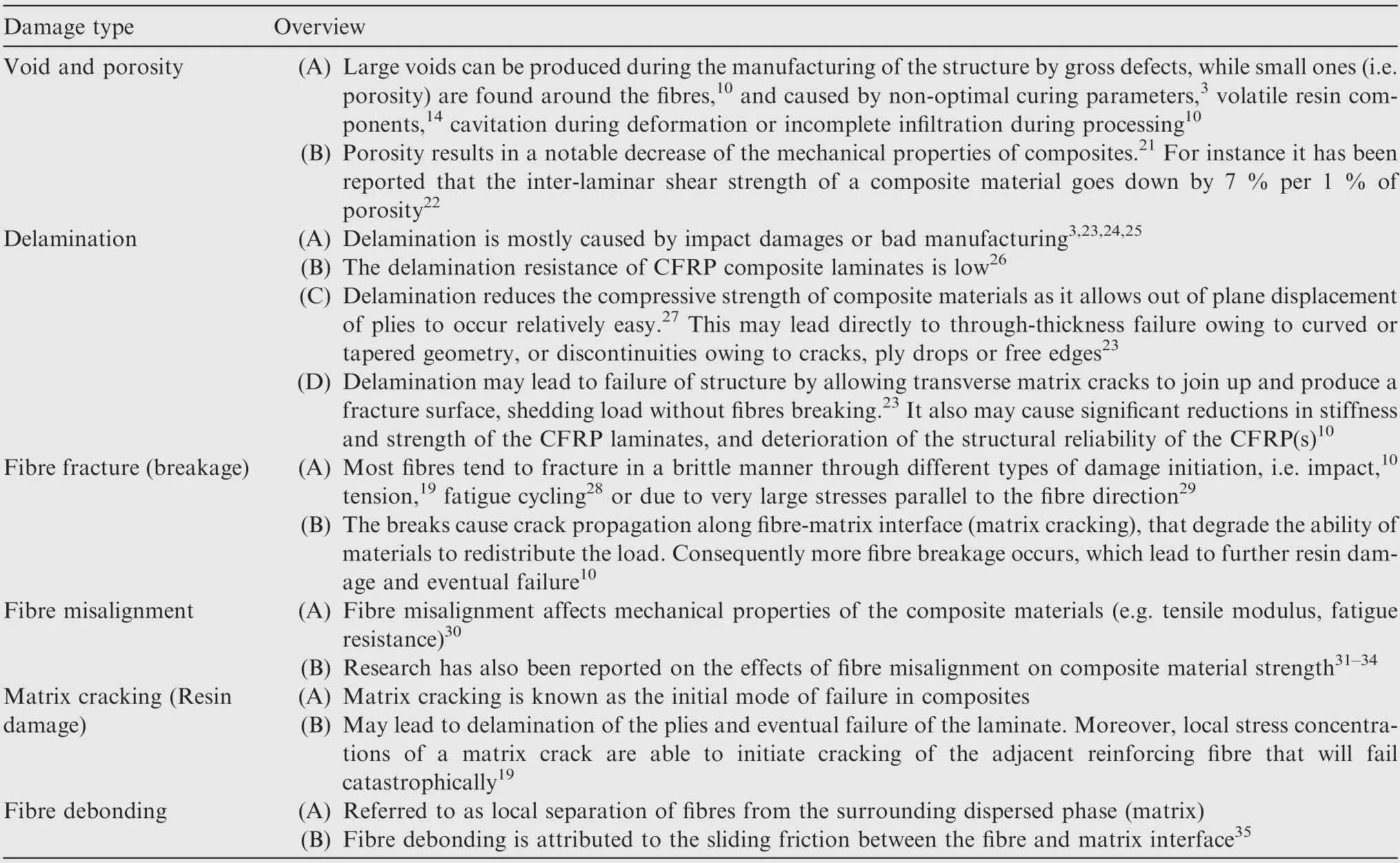
Table 1 Overview of different types of damage in composites.
(A) Aerospace composites are generally applied in thin,large plate structures, such as aircraft wings and tails.These structures therefore have extremely high aspect ratios and the NDT technique used must be able to inspect large surfaces.
(B) Composite structures are typically shaped in complex and variable geometry which is challenging for NDT inspections.
(C) A high-speed inspection technology,without a necessary need to access both sides of a component, is critical to inspect large panels in a highly competitive aerospace environment.
(D) NDT of hybrid materials,which are increasingly used,is challenging due to multiple interfaces, complex geometries limited access and different elastic properties.
(E) The probability of defect detection must be increased to provide a high confidence interval specifically for BVIDs.
(F) Three dimensional inspection of structures is desirable to evaluate details such as hidden geometries, assembly induced defects(e.g.missing parts or wrongly assembled parts), hidden defects (e.g. in skin-stringer connections or in internal stiffeners), fibre structure and so on.
2. NDT methods
2.1. Ultrasonic testing (UT)
2.1.1. Principles of UT
Ultrasonic waves propagate in composite materials, provide information about the interface of base material and discontinuities and hence, location, size and orientation of the defects can be detected.57Among different type of UT representation methods,58,59,60UT C-scan is a valuable tool to monitor the transmission losses caused by delamination and disbonds,volumetric defects including voids61,62and damage detection in composite laminates under both low energy63and high energy64impacts. During UT inspection of fibre reinforced composites, the sound beam propagates in a direction along the axis of the reinforcement fibres65and therefore defects such as fibre misalignment can be characterised efficiently.66Delamination and fibre debonding can cause a discrete reflection (as well as loss of transmission) from a particular depth in the material and hence can be also detected at a high confidence interval. Porosity does not produce a discrete reflection but scatters the ultrasonic waves, and also results in transmission loss14that can be well characterized as detailed in.67Research has also been reported showing that the attenuation of waves propagating perpendicular to CRFP plies could provide information to identify and interpret interlaminar quality.68In order to increase the probability of defect detection and to improve the localization of defects, various signal processing techniques in time domain and frequency domain are used69-72to distinguish the defect echoes from the multiple waves that are reflected from the surfaces of the CFRP composites.Recently, a novel signal post-processing method was introduced in73to overcome the problems related to the rough surface and non-parallel layers in a multi material joint i.e.CFRP bonded to titanium when inspected by a high frequency focused ultrasonic transducer.
On the basis of conventional UT, more advanced methods have been developed such as phased array ultrasonic testing.74,75Nowadays, phased array sensors can be integrated with time reversal techniques76that compensates for the misalignment between the probe and composite structure(due to complex geometry of aerospace composites), and increases the coverage area of sensor.77At Airbus Operations GmbH2Stade plant, Germany.large ultrasonic scanners,equipped with phased array technology,automatically inspect big composite aircraft structures like Vertical Tail Planes (VTP) or wing cover shells of A400M and A350.
2.1.2. Challenges for UT inspection of aerospace composite structures
The notable impedance mismatch between air and solid materials means that popular honeycomb constructions can be difficult to inspect.78A common approach is to couple the sound from the transducer to an object by immersing the transducer and object in a tank of water, a procedure called ultrasonic immersion testing that usually provides better results.79However, honeycomb panels can absorb water requiring subsequent drying. Moreover ultrasonic immersion technique requires dismantling of the test-object from the structure which may cause some disruption in the operation of aerospace structures. The inspection process may take many hours to complete. To speed up the inspecting procedure of the large surface areas, NASA Langley has chosen to implement a captive water column coupling approach,80that provides coupling similar to immersion testing without requiring the constant stream of water.9Additionally,recent advances in using wheel coupled and air coupled sensors in immersion testing have also increased the speed of scanning and simplified mandatory in service inspection of aerospace components.81The difficulties in coupling have led to the development of laser generated ultrasound,which has the potential to monitor structures with complex curvatures,66,82however the technique requires higher costs and is not yet commonly applied in industrial applications.
UT is also slow compared to other modalities due to its nature using point-wise measurements that may takes a few hours to inspect large composite panels. In addition, UT has limited resolution and its ability to track the interaction of various defect types or to detect hidden defects is poor. To get higher resolution,high frequency(5-20 MHz for inspection of objects with thickness from 2.5 to 13.0 mm83) and highly focused transducers with the bandwidth up to 100 MHz can be employed.84However this technique only leads to higher axial(or range)resolution.If even higher resolutions are needed,yet higher ultrasonic frequencies(in the range of 30 MHz-2 GHz),can be employed in so called Scanning Acoustic Microscopy(SAM) to examine microstructure of composite materials.The technique has shown to be very sensitive to interfacial debonding and microscopic crack damage growth.85,86
Ultrasonic testing is still facing serious challenges to detect discontinuities in a non-homogenous material such as composite laminates or sandwich panels due to multiple reflections and large scattering of waves. This method is not satisfactory for the detailed characterization of defects due to high attenuation coefficient of ultrasonic waves caused by absorption in porous resin and scattering by the fibers.78Therefore compare to the use in homogenous materials, lower frequencies are applied in inspection of CFRPs to reduce attenuation,79thus the penetration depth decreases so that UT is often not able to characterise defects that are far below the surface of a CFRP component.
In addition, the ultrasonic attenuation coefficient is also affected by the size,shape and spatial distribution of the voids in composite structures.Consequently a considerable measurement errors,in the range of±25%,can be generated.87,88In89broadband laser-ultrasonic spectroscopy was used to verify applicability of the Kramers-Kronig relations90between the attenuation coefficient and phase velocity of longitudinal ultrasonic waves (in the range of 1-10 MHz) in inspecting of CFRPs and satisfactory results have been reported.
A further limitation of ultrasonic testing of aerospace composites is the shadow effect.The shadow effect is caused by any large delamination located close to the surface.These large discontinuities reflecting the majority of ultrasonic energy allowing only reduced visibility below a delamination.2
2.2. Acoustic Emission (AE)
2.2.1. Principles of AE
AE waves,as structure-borne waves which are similar to Lamb waves,91propagate in all directions into the surface material and measured by an AE sensor.92-94In composite materials,AE is generated due to matrix cracking, delamination, fibrematrix debonding, fibre pull out, fibre breakage and fibre misalignment which have been very well documented.95-98These source mechanisms release higher AE energy in a short period of time(this is called a transient type or a burst type AE signal) and hence can be characterised more easily compared to other defects. For the same reason, AE measurements have been proven to be effective indicators of impact damages.97,99
AE features extracted from the AE waveform in the time doman,96,100,101along with AE spectra102,103are widely used for the purpose of NDT of composite structures.The extracted features are sometimes fed into a classification algorithm that makes the decision about what condition the component is in.As an example, Grondel et al.104used AE measurements to detect of impact damage and fibre debonding between stiffeners and composite skins in a wing box structure.They reported that the amplitude of AE signals increases proportionally with the impact energy increase. They also mentioned that UT Cscan with a 15 MHz straight beam contact probe did not reveal BVIDs following those impacts. In contrast to,104where damage development can be characterised only by the amplitude of AE waveform, usually more advanced signal processing techniques are required to characterize AE signals based on specific types of damage mechanisms.105,106For instance, the AE raw data recorded from different defects in a composite material are compared in.107They reported that the amplitude of AE signals recorded from matrix cracking and fibre debonding are relatively similar,although,fibre failure generated much lower AE amplitudes.This clearly shows that more sophisticated signal processing techniques are required to distinct defective structures from the healthy ones, as well as to separate different defects from each other (i.e. matrix cracking and fibre debonding).
Research has been reported on the application of different signal analysis techniques such as Artificial Neural Networks(ANN),108auto regressive modelling,109principal component analysis110and supervised and unsupervised classification techniques111,112for damage diagnosis and defect distinction of aerospace composite materials based on AE measurements.
2.2.2. Challenges for AE inspection of aerospace composite structures
Each AE event is a unique stress wave and cannot be stopped or reproduced.This means that a particular test is not perfectly reproducible due to the nature of the signal source,e.g.a slow growth of a crack generates a weak AE signal, while rapid crack development of the same size produces a transient signal.94
Moreover, AE signals in composites will incur significant changes across the transmission path to the receiving AE sensor. Coupling of AE sensors is also required and measures have little explanatory value in terms of defect mechanism.
2.3. Eddy Current Testing (ECT)
2.3.1. Principles of ECT
In ECT, as shown in Fig. 1, the in-situ integrity of the electrically conducting objects is evaluated by correlating the measured impedance, as the coil is brought near an object, with calibrated defect dimensions.A very good overview of the fundamentals and main variables of eddy current testing is found in.113
It has recently been demonstrated that eddy currents could be used for the inspection of conductive composite materials10,114such as CFRP and metal-matrix composites. In CFRPs,ECT measurements respond specifically to the carbon fibres, which make eddy currents suitable for detection of low energy impact damage,115thermal damages,66fibre damage with or without matrix cracking,116and other damages that affect the fibres in the sample material.66
In117a High Frequency Eddy Current Technique (HFECT) was developed to visualise fibre orientation, fibre fraction fluctuations,resin reach regions,delamination and impact damage in CFRP composites. HF-ECT are considered to be better suited for less conductive materials. However, HFECT is more affected by various barriers in the system implementation. Moreover, when high frequencies (e.g. 50 MHz or above) are applied, the depth of penetration will be limited to the top few plies below the sample surface, and therefore only near surface defects can be characterized.66
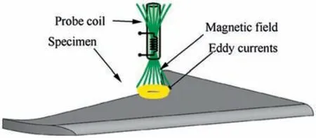
Fig. 1 Principle of ECT.
With lower frequencies, it is possible to evaluate the integrity of the sample material deeper below the surface. Therefore, low frequency ECT is more popular for sandwich structures. For instance He et al. investigated low frequency scanning pulsed eddy current to characterise the different types of defects in CFRP laminates and internal inserted defects in honeycomb sandwich panels.118They reported that magnetic field intensity, as a characterising feature, is more affected by low-energy impact whilst delamination has more influence on the local conductivity. In another work, Cheng et al.119developed a high precision low frequency ECT (up to 250 kHz system) and reported that several defects including fibre orientation, misaligned fibre bundles, cracks, delaminations,impact damage were detected and visualized in the scanned images.
In addition, more advanced methods of ECT such as eddy current holography have been developed to evaluate the integrity of composite structures for a variety of defects such as surface and near surface cracks, corrosion and delamination.Eddy current holography technique has been applied to view the delaminated regions in quasi-isotropical carbon-epoxy composites, and it was reported that delaminations produced by impact energies exceeding 0.75 J were successfully visualized.120
2.3.2. Challenges for ECT inspection of aerospace composite structures
ECT suffers from some limitations when applied for NDT of CFRPs. Measured signals are hard to interpret, for instance it is difficult to distinguish delamination from interlaminar cracks. Penetration depth is not too high and mainly detects surface and subsurface defects. The technique is limited to composites containing conductive fibres, e.g. carbon fibre,and most of the time needs modifying for less conductive structures.
Moreover,the application of ECT in an industrial environment is still limited due to several interference factors.Finally,lift-off effect that is referred to as changes in the mutualinductance between the excitation coil and the test sample due to variation of the distance between the probe and the test sample121and surface condition needed to be considered.
2.4. Infra-Red Thermography (IRT)
2.4.1. Principles of IRT
When thermal energy propagate inside the object by diffusion and reaches a material defect (e.g. inclusions, delaminations,matrix cracking and porosity), a thermal gradient is generated due to different emissivity coefficients that can be used to evaluate the damage.122The thermal output of the material,in the infrared electromagnetic band of the used detector (infra-red camera), is analysed to get a surface temperature map of the structure under inspection, Fig. 2. Therefore it is possible to detect the defects in composites particularly when they have very different thermal properties from the base material.
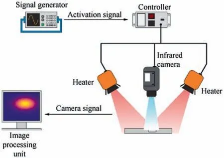
Fig. 2 Principle of IRT.
NASA has been using IRT for on-orbit inspection of manned flight vehicles for a number of years.9Many researchers have also investigated the application of IRT for the rapid inspection of large aerospace components such as aircraft primary and secondary structures,spacecraft components and its subsystems and jet engines and turbine blades.123-125Current research in the field is investigating to develop robotize line scan thermography techniques to inspect large composite structures.126,127Fig.3(a)shows a collaborative robot(cobot)performing IRT on a composite aircraft fuselage structure and Fig. 3. (b) shows the processed and registered results.9
2.4.2. IRT techniques for NDT of aerospace structures
IRT is generally classified into ‘‘passive” and ‘‘active” thermography. The former, passive IRT, is typically used for objects or features of interest that are not in thermal equilibrium and have a thermal contrast to the surrounding environment. As an example, passive IRT can be applied to detect water ingress after aircraft landing due to a significant temperature gradient between water and the aircraft.128
In Active IRT,however,the structure is externally exposed to thermal energy to induce a temperature difference between the regions of interest using different heat sources.Active thermography has been frequently applied for NDT of aerospace components.124,129Several studies developed various systems that use different physical source of heat,130-132whilst other studies looked at advanced signal and image processing methods133-138to achieve the highest Signal to Noise Ratios(SNR).A very good survey on active thermography, different heat sources, digital image post processing and thermographic signal reconstruction can be found in.139
Based on the employed external heat source, active IRT is generally subdivided into optically stimulated thermography,140ultrasonic stimulated thermography,131,141,142eddy current stimulated thermography132and metal based thermography.143Optically stimulated thermography is the most widely used configuration in IRT of aerospace structures.The common optical methods for aerospace applications are pulsed or transient thermography (by applying a short flash)and lock-in thermography which will be detailed briefly in the remainder of present section.
Pulsed thermography,that produces a better signal-to-noise ratio than lock-in thermography for shallow defects,122has been applied for in-situ monitoring of CFRP components of space shuttle by NASA144and for the evaluation of disbonds in the insulation of solid rocket motors made of elastomers.138However, in pulse thermography data is affected by problems such as non-uniform heating, environmental reflections and surface geometry and therefore more advanced signal and image processing techniques are needed as reported in.145,146Therefore, different techniques such as heat conductionbased three dimensional normalization,147coefficient clustering analysis,135Gapped smoothing algorithm134and partial least-squares regression148have been applied frequently in the literature.
Compared to the pulse thermography, lock-in thermography allows better control of the energy deposited on surface of the structure145whilst for deeper defects,the two techniques produce approximately the same signal-to-noise ratio.122Lock-in thermography has been successfully applied to detect disbonds in titanium alloy honeycomb sandwich structures,149to NDT of BVID(s) in thick glass fibre-reinforced composites,150to detect subsurface defects in CFRP(s),151,152to characterize delamination in CFRP(s)153and to investigate the fatigue behavior of CFRP(s).128However lock-in thermography requires a separate experiment for every single inspected depth and there is a stabilization time before reaching a steady state regime.145
Since impact energy,which is dissipated as heat,is spent in the formation of defects such as matrix micro cracks, fibre breakage and delamination, therefore, IRT is a superior method to detect those defects.66Several studies demonstrate the detection of impact induced damages in aerospace structures using both pulsed154,155and lock-in149-152methods.Other studies looked at damage evolution in aerospace composites156using IRT. The idea is widely held that an abrupt rise of temperature indicates fibres breakage and matrix cracking while lower temperature differences indicate delamination.
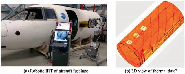
Fig. 3 Use of cobot in NDT.
Moreover, it has been demonstrated that using an infrared imaging device during the impact may allow to get real time information on the development of the delamination that occurs on the laminate surface opposite to the impact.157,158
In addition to impact damage detection, research has looked at machining induced defects (i.e. notches, delamination, and drilling induced defects) in CFRP structures. Avdelidis et al.159applied pulsed IRT to CFRP laminates as well as honeycomb and sandwich structures and reported that real-time monitoring of all features was obtained using pulsed thermograph.Nonetheless they reported that the success of the technique is highly dependent on defect depth and size, which restricts its application to near-surface defect imaging.
2.4.3. Challenges for IRT inspection of aerospace composite structures
Most of the above studies are limited to near field heating (in other words, near surface damage detection). For instance Maierhofer et al.160reported that the aspect ratio of the defects at the detection limit is between two and three while in aerospace applications, higher aspect ratios are expected.
Moreover,Meola et al.158revealed that thermography fails to appraise the whole extension of the delaminated zone due to effect of local material non-uniformities that generates similar small variations in thermal energy.It has also been reported in Ref. 161 that the temperature contrast observed on the composite laminates decreases with increasing different orientation angles between neighbouring layers.For this reason,the detection of defects in cross-ply or multi-angle ply laminates is more difficult than in unidirectional laminates especially when inspecting thick CFRP laminates reinforced with fibres that have a high thermal conductivity (e.g. pitch-based fibres).
Therefore according to the above understandings, in either impact induced or machining induced defects, the IRT is limited to near surface damage detection with low aspect ratios.The technique is not very sensitive to in-depth damages and micro-cracks with dimensions ranging from ten microns to few millimeters.124,162Local material non-uniformities as well as orientation angle between neighbouring layers have also been reported as a challenge to effectiveness of the technique.
2.5. Laser Shearography (LS)
2.5.1. Principles of LS
Shearography when applied in the aerospace industry offers several potential advantages including high speed and real time monitoring of large composite panels.163,164Due to these advantages, LS is currently applied to NDT of a wide variety of aircrafts including F-22,F-35 JSF, Airbus, Cessna Citation X, Raytheon Premier I and the NASA space shuttle.165
A typical set-up of digital shearography is illustrated in Fig.4.The physical principle of the technique is based on processing the interferometry images achieved using two laser beams with an identical wavelength that becomes nearly collinear. The test object is imaged by a charge-coupled device CCD video sensor. Because of the inherent surface roughness of the test object, the interference produces a random pattern known as a speckle pattern.166The speckle pattern will be slightly altered when the object is externally loaded or deformed. Loading is needed to induce some deformation or alter the deformation state of the surface of the sample.
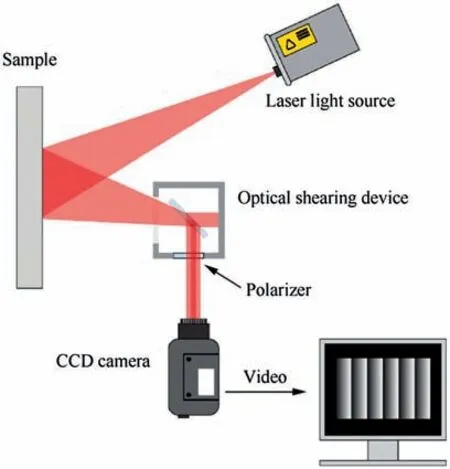
Fig. 4 Fundamental of digital shearography.
The integrity of the object is then evaluated by two sequentially digitized speckle patterns(before and after deformation).Subtracting of the two speckle patterns produces a fringe pattern depicting the displacement derivative with respective to the direction of shearing.166This can be done in realtime.164,167A further improvement in image quality can be obtained with quantitative evaluation methods using spatial carrier frequency or temporal phase shifting.168More details on the technique, its principle of operation, optical configurations, image processing algorithms and applications can be found in Ref. 169.
Loading systems that are frequently used in shearography include vacuum shearography, thermal pulse shearography,pressure shearography and vibration (acoustic) shearography.More detail on the mechanism of different loading systems can be found in Ref. 139.
Vacuum shearography has proven to be highly effective for imaging fibre debonding in CFRP laminates,170aluminium /aluminium honeycomb panels,171as well as in a composite element panel of the tail unit of a helicopter(honeycomb core and two external skins in graphite/epoxy),168delaminations, core damage and core splice-joint separations.165This loading system is the most common arrangement in which the specimen is uniformly stretched by negative pressure difference between the inspected surface and the enclosed space.Therefore defects will tend to manifest themselves as a fringe anomaly during vacuum shearography. However, the application of vacuum loading is limited to disbonds with enclosed boundaries (e.g.metal/metal honeycomb bonds) and may not be applicable if the flaw is open to the atmosphere (i.e. skin panel to stringers bond).139
Thermal pulse shearography, another loading system, has proven to be effective for BVIDs. Ref. 172 reported that in polymer plates with a thickness of 10 mm, the minimum detectable diameter is 0.8-1.3 times of the depth using thermal loading. It has also been reported that when the direction of image shearing is not perpendicular to the crack orientation,the sensitivity for defect detection is relatively higher than with perpendicular image shearing.172
Vibration shearography has been applied successfully to inspect the foam on the external tank of NASA’s space shuttle165as well as to reveal flat bottom holes made with different sizes and placed at different depths in CFRP laminates.173
2.5.2. Challenges for LS inspection of aerospace composite structures
A notable limitation of shearography is the need to apply suitable external loading increments to the test object during inspection. For that reason, suitable loading methods are required. Moreover, the changes observed in the derivative of the displacement pattern decreases as the depth of the defect or its diameter is increased.1Consequently, a successful application of digital shearography for characterization of defects(except for delamination)of aerospace composites is extremely difficult and still depends on so many factors such as depth and type of defects, the type of materials, and laser illumination and so on.167Therefore shearography is sometimes paired with other types of non-destructive evaluation techniques that can help to identify certain defects.174
2.6. X-ray radiography (XR)
In X-ray radiography, short wavelength electromagnetic radiations (high energy X-ray photons) are used to penetrate various materials and generate a shadowgraph image of the test object. The denser the material, the longer the path length and the higher the X-ray absorption,the more the X-ray radiations is attenuated while it passes through the test object toward an X-ray detector. The interactions of X-rays of a specific energy with matter is characterised by the Beer-Lambert law as following:

where I is transmitted beam intensity,I0is incident beam intensity, μ is the value of linear attenuation coefficient at point (x,y,z) along the path ray that occurs due to the photoelectric effects and scattering, and where integration is over the line l between X-ray source and detector. Therefore, the variation of the image darkness (density) in different locations indicates that there is a difference in material density,material thickness or the both between the corresponding spots in the test object.This is the way by which different defects can be characterized.
Conventional radiography is one of the most popular techniques for the detection of non-planar defects such as solid inclusions, fibre misalignment and matrix cracking in aerospace composites, if their orientation is not perpendicular to the X-ray beam.58,174-176However,overlapping defects cannot be separated if the defects are superimposed onto a planar surface,and depth quantification is impossible unless radiographs are taken from multiple angles.
On the basis of conventional X-radiography, more advanced techniques such as X-ray Computed Tomography(XCT or CT) and X-ray Computed Laminography (XCL or CL) have been developed for visualizing interior features within components, and for obtaining digital information on their three dimensional geometries. These methods modify the scale of NDE from macroscopic to microscopic scale and have a promising potential to overcome the current challenges in monitoring the highly sensitive aerospace materials as detailed in Sections 2.6.1 and 2.6.2.
2.6.1. Computed tomography for NDT of aerospace composites
CT provides an excellent imaging technique to characterise the size and volumetric details to a high accuracy, and in three dimensions177,178which is particularly useful for NDT of aerospace composites where inspecting the structural integrity of the components (i.e. hidden and complex geometries) is critical. In computational NDT, as an active research area for NASA’S Non-destructive Evaluation Sciences Branch(NESB),9CT results are applied to show the complex nature of damages in composite laminates. These results are then fed into a elastodynamic finite integration technique software54to simulate the interaction of guided waves with the internal damages (e.g. delamination damage179). CT is also the gold standard in air crash investigations.180
To generate and extract useful information from a CT data set, a chain of steps are required: as shown in Fig. 5. Tomographic information is acquired from a number of radiographs(or projections) taken systematically from a sequence of increasing viewing angles (or ‘projection angles’) by placing the object on a rotary plate between the X-ray source (either monochromatic or polychromatic) and the detector. Once the projections have been acquired, the object is reconstructed by feeding the projection images into a‘reconstruction algorithm’.Most CT systems implement a form of the Filtered Back Projection (FBP) reconstruction algorithm due to the predictable nature of FBP algorithms in terms of computational cost and reconstruction times.181To achieve an approximation of the scanned object by FBP (no exact solution exists away from the central slice182),the ray integrals for each ray path(see Refs.181,183,184 for more details) are projected back through the object.FBP techniques work well if sufficient,low noise projection images are available, however, in more challenging settings, alternative iterative reconstruction methods can have significant advantages.183-185Iterative algorithms use a discretised forward model of the X-ray acquisition process and employ a host of optimisation algorithms to invert this model.Once a CT volume has been reconstructed,useful information can be extracted using image viewing and processing techniques, a step known as visualisation. The image quality achieved is mainly determined by the competing influences of noise, contrast, spatial resolution,186and artificial features known as artifacts186-189e.g.beam hardening and scatter.190-192
Most work on the use of CT of aerospace composites has concentrated on scanning of coupons or small panels, but not on actual components or structures. This limitation arises from two facts:
(1) Detector pixel size restricts resolution which depending on component geometry is often 2-3 times the pixel size.193
(2) The effective area that is covered by the detector is typically 2000-4000 pixels wide194and this thus restricts the size of the test object. In other words, the details acquired by using current generation of CT systems is affected by the sample size.195
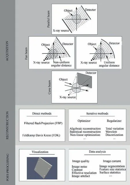
Fig. 5 An overview of CT process.
(3) For these reasons, Ref. 194 conclude that samples must be no larger than 1000-2000 times the smallest feature size leading to the so called ‘component size limitation‘in CT applications.Other limiting factors include:attenuation contrast,in-situ monitoring and field of view limitation as detailed in the remainder of this section.
2.6.1.1. Attenuation contrast. Since the attenuation contrast between carbon fibres and resin is very low,175accurate quantification of porosity, fibre architecture, narrow fatigue induced cracks,and impact damage in CFRP materials is challenging.Therefore, most research in this area has been carried out using X-ray micro-tomography (or μ-CT) systems.196-198The principals of μ-CT is the same as CT,however,the source uses an X-ray spot size(the area of the anode target hit by electrons that generates thermionic emission199) that can be measured in the tens of micro meters, allowing the use of conebeam magnification to achieving micrometre resolution of the same order as the spot size.
2.6.1.1.1.Porosity.μ-CT has been applied to the quantification of porosity in carbon based composite materials200,201as well as the investigation of the evolution of porosity in outof-autoclave cured fibre/thermoset-matrix systems.202The main barrier to the quantification of porosity in composite materials with cone beam CT systems is the determination of the surface between material and air. The measured porosity is strongly dependent on the segmentation method and parameters used.203,204This problem, if solved reasonably, allows porosity characterization by standard CT systems rather than μ-CT systems.In 2010,Kastner et al.presented a segmentation method to evaluate CT data for the purpose of porosity measurement with a high level of repeatability and accuracy in CFRP materials.205Similar results have been reported in.206-208
2.6.1.1.2. Fibre architecture and placement. For unidirectional composites with no macroscopic fibre tow geometry, individual fibres are not resolvable on standard μ-CT cone-beam systems. Assuming that carbon fibres are typically less than 10 μm in diameter, then the sample size must to be smaller than 6 mm194to image individual fibres.In out-of-autoclave cured composites, e.g. two dimensional and three dimensional woven composites, however, the relatively low laminate compaction and high porosity allows fibre architecture to be identified by using contrast agents.183For instance198,209demonstrated that coating of fabrics with gold,copper, and an iodine contrast agent (0.025-0.05 μm coating thickness) allowed the measurement of fibre dimensions and orientations, along with ply thicknesses. However, they reported the presence of beam hardening artefacts in the reconstructions due to presence of the highly attenuating coatings. Moreover, contrast agents may affect the mechanical properties of the composite materials.210
2.6.1.1.3. Impact damage characterization. CT has been used to analyse impact damage in CFRP materials including determination of delamination distributed throughout the thickness of a unidirectional CFRP panel,211examination of the impact behaviour of woven carbon fibre epoxy laminates under different levels of impact energy212and demonstration of crack initiation at stitch locations of through thickness stitched uni-directional laminates.213The dimensions of coupons applied in these studies are relatively large (to be imaged at the required resolution on standard CT)due to the requirements of standard impact test,see.211,212These large,thin samples used in general impact test, are far from ideal for CT imaging.194In these specific cases, laminography, as detailed in Section 2.6.2, offers some advantages.
2.6.1.1.4. Fatigue induced damage characterization. Fatigue induced damages in CFRPs often occur in various curved planes and their interfaces.23The majority of studies on fatigue behaviour of composite materials have been carried out at the macroscopic scale to evaluate the effect of damage accumulation on the degradation of the material properties, however,attention has recently focused on building up a micromechanical understanding of fatigue induced damages.194For instance the investigation of toughening particles on crack propagation in carbon/epoxy composites has been reported in the literature.214-216
At continuum scale217developed an algorithm to rebuild the reconstructed μ-CT volume allowing better visualization of the fatigue induced damage in a CFRP coupon subjected to fatigue testing, Fig. 6. These type of damages often occur in various curved planes and their interfaces which are otherwise planar before bending occurs. Therefore, they are one of the most difficult damage types to visualize.However,their μ-CT scanner with the resolution about 15 μm-20 μm,was not able to resolve individual carbon fibres.Similar work has been reported in218that did not demonstrate sufficient resolution to distinguish fibre failure during the fatigue testing of glass fibre composites.
2.6.1.2. In-situ monitoring. In situ monitoring of aerospace composite panels, e.g. damage initiation and progression under fatigue loading, is extremely difficult using X-ray CT systems and thus has been less frequently reported in the literature. This is due to, on one hand, the high aspect ratio of aerospace structures and on the other hand is due to the requirements of mounting test rigs within laboratory X-ray CT systems. The test object should be positioned as close as possible to the source to achieve the maximum special resolution for cone beam imaging. In addition, the system needs to be designed so that it allows X-ray illumination of the test object as described in.214-126,219,220
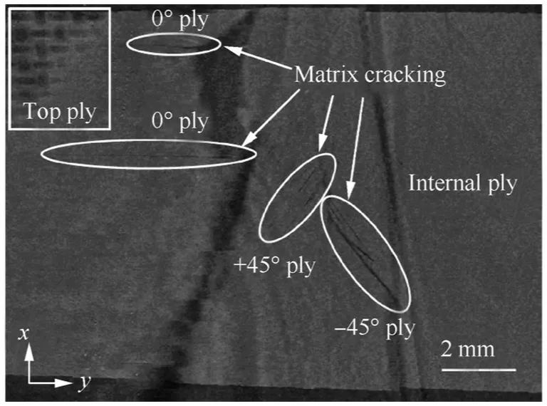
Fig.6 A μ-CT slice showing internal fatigue induced damages in a CFRP coupon.217
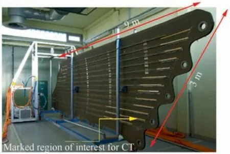
Fig. 7 Mobile CT of a fibre composite shell of an A400M vertical tail plane shells.7
2.6.1.3. Field of view limitation. When an object is extended beyond the Field of View(FoV)of the detector,e.g.the structure shown in Fig.7,7if longitudinal and transversal diameters differ substantially, or when the path lengths through the scanned object vary dramatically at different angles,then scanning and reconstruction is difficult. Moreover, high aspect ratio objects may lead to large variations in beam transmission leading to artefacts in the reconstructed volume.In such cases,there even is a risk of collision between object and X-ray source so that the source has to be positioned away from the object, leading to poor resolution.
To overcome FoV limitation,three strategies are used,dual energy scanning, Region of Interest (RoI) scanning and computed laminography. Dual energy scanning221-224performs two scans with different X-ray energies, one optimised for the thin path length and one optimised for the longer path length. These projections are then combined into a single set of radiographic data that is reconstructed to give an improved reconstruction.RoI imaging allows small volumes of an object to be imaged at high resolution. The majority of studies on RoI scanning have employed data completion methods to overcome the truncation problem, which occurs if some parts of the object are not reconstructed. Examples include those in parallel beam225and cone beam acquisition.225,226The use of a priori information(e.g.CAD data)available for an object can also improve reconstruction.227,228
2.6.2. Computed laminography (CL)
Laminographic scanning is similar to CT, however, the motion of the sample and the method of reconstructing the scanned data differ from conventional CT. In contrast to CT, in laminographic data acquisition only a limited amount of tomographic information is required. Therefore, scanning time using CL is lower that makes it appropriate for aerospace applications, since it typically uses few radiographs acquired with a single peak energy. Moreover, this arrangement ensures that X-ray transmission is similar at each incremental rotation angle and allows laterally extended samples to be imaged at locally high-resolutions (~1 μm).183,229,230CL can potentially produce better-quality images than a limited-angle CT scans, especially where the limitation on angular range is severe.231High-resolution in situ volumeimaging of composite structures is therefore achievable at levels that would be impossible via CT or with any other three-dimensional NDT methods.
2.6.2.1. Crucial aspects of computed laminography. In practice,it is important to tune the trajectory of a CL system to balance the trade-off between the amount of acquired laminographic information against the weight dimension and geometry of the object. There are different approaches to acquire laminographic data, Table 2232,239provides a brief overview on the most popular scanning geometries that applied in CL.
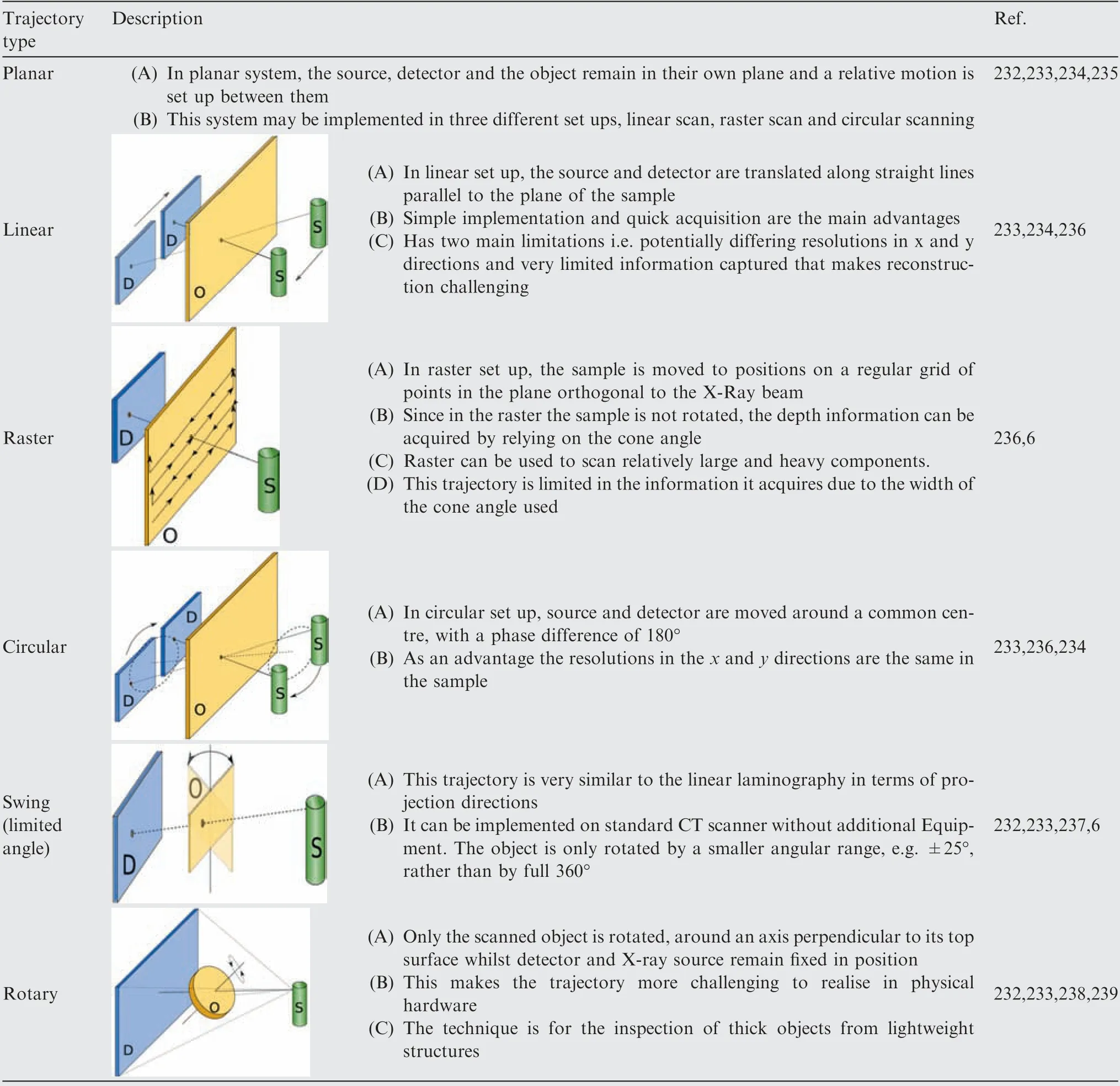
Table 2 Summary of scanning trajectories.
Research has been reported on the possibility of undertaking laminography using laboratory CT systems by using a rotary scan.239,233Moreover, if additional sample motion system is provided, other trajectories can also be generated using laboratory X-ray CT systems.Wood et al.6examined different sample manipulator systems (i.e. Hexapod robot vs six-axis Robot) positioned in a Nikon Metrology Custom X-ray CT scanner to investigate the effect of different laminographic scan trajectories as well as the performance of manipulator systems. The specimen measures 300 mm×300 mm×5 mm(note that the sample is much larger than that to be imaged at the required resolution on standard CT)and made of CFRP laminates with a copper mesh lightning strike protection on one side.They compared raster and limited angle scanning trajectories in detecting several impact damages with range of energies. Looking at a range of images, they reported that in general, the limited angle reconstruction has lower resolution than the raster one.Based on the conclusions they made,raster like scan trajectories with more complex surfaces may allow the application of technique to more complex structures such as large composite fan blades in jet engines.They also visually found that the Hexapod manipulator system leads to a better resolution compared with the robot arm.
For certain trajectories, filtered back projection methods can be adapted for reconstruction, whilst iterative methods can be applied more generally. In general, iterative methods provide better image quality.240,241One of the important advantages of iterative methods when compared to filtered back projection methods is their ability to incorporate a priori information, e.g. CAD data, about the object into the reconstruction process.242O’Brien et al.238used a simplified model of composite panel (measures 70.7 mm×70.7 mm×4 mm),which had certain defects. They examined both Simultaneous Iterative Reconstruction Technique (SIRT) and Conjugate Gradient Least Squares (CGLS) reconstruction algorithms and mentioned that both methods show promising results. It has been shown that employing the iterative reconstructing algorithms with priori information reduce laminographic blurring artefacts and increases contrast, thereby allowing for a higher probability of defect detection and thus a more reliable NDT of the aerospace structures.242-244
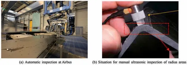
Fig. 8 Ultrasonic testing of aerospace structures.8
2.6.2.2. Laminography for NDT of aerospace composites. In aerospace applications, Computed Laminography (CL), as an approach that does not require a full rotation for subsequent reconstruction, is an alternative technique to standard CT scanning which overcomes the sample size, shape, and attenuation rate problems discussed in Section 2.6.1. CL also provides a viable alternative to ultrasonic inspection, as a certificated mandatory NDT method in aeronautics applications,when inspecting extremely flat or slightly curved aircraft structures.As an example,Ref.8 reported the difficulty of getting a stable back wall echo in ultrasonic inspection of C-shaped frames, Fig. 8 (note that this part is still inspected manually due to its complex geometry and the sharp corner), especially for small radius of 5-8 mm combined with higher laminate thickness of approximately 20 mm.Laminography has already been qualified at Airbus since 2008 for inspection of cracks in A400M vertical tail plane shells,8allowing the flaws detection with a POD of 90% within a confidence interval of 95%.
In 2010,Moffat et al.229applied CL with synchrotron radiation to investigate the possibility of high-resolution imaging of large CFRP panels with total thickness of 1 mm. They carried out two experiments.Firstly,a relatively small sample size was used to compare CT and CL imaging of damage features as illustrated in Fig. 9. Composite defects such as resin-rich regions and misaligned fibres can be successfully identified in both cases.
In second imaging experiment, composite panels which are potentially larger than that size to be scanned at a high resolution on conventional CT systems (measure 70 mm×60 mm)were subjected to progressive damage development from a deep notch.Imaging around the notch tip was performed using a monochromatic X-ray beam at an energy of 20 keV.229The possibility of micromechanical assessment of damage mechanisms has been demonstrated, Fig. 10.
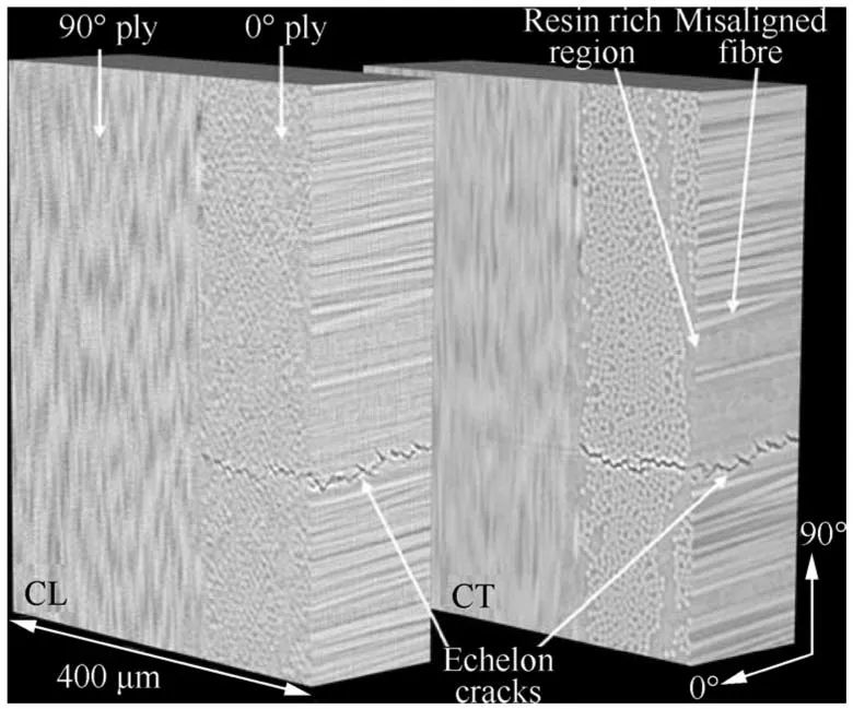
Fig. 9 Comparison of volumes produced using CT (right) and CL (left).229
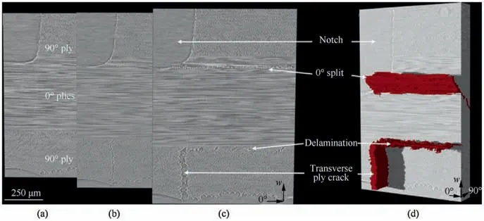
Fig.10 Set of three CL images of approximately the same slice in the same volume of Fig.9,imaged at different loads:(a)The unloaded state,(b)and(c)At progressively higher loads.In(d)the damage has been segmented and the surrounding material cropped to reveal the 3D nature of the cracks.231
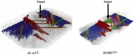
Fig. 11 Three dimensional segmentation revealing the damage morphology surrounding the impact region within the same specimen obtained by (a) μ-CT with the dotted region indicating the region obtained using (b) SRCT.246
The successful application of CL for defect detection of aerospace composites using even larger composite panels has also been reported in the literature.For instance Rehak et al.236examined the ability of CL to detect the defects in different depths of a 240 mm×140 mm test object that was 12.5 mm thick. The CFRP laminate had a set of bores, each 3.0 mm in diameter and of known depth and including some glass fibres.
Laminography if applied with RoI scanning offers better resolution to levels less than a carbon fibre diameter.245In Ref.246,three dimensional morphology of the impact damage was segmented in the same ‘matchstick’ specimen using μ-CT and Synchrotron Radiation Computed Tomography (SRCT)data, as shown in Fig. 11. The field of view for SRCT was smaller than that of μ-CT, hence the smaller segmented volume. Blue is representative of delaminations whilst other colures indicate matrix cracking occurring on each respective ply. As it is evident, different defects have been characterized successfully demonstrating the effectiveness of this approach for critical inspections in aerospace industry.
3. Summary of comparative studies
In previous section, a review on the capabilities of certificated NDT modalities for inspecting aerospace composites has been covered with respect to advantages and disadvantages of these methods. It has been shown that none of the NDT methods can be considered as a superior technique to evaluate the integrity of aerospace structures. Fig. 12 summarizes applicability of some NDT methods for detecting common type of defects in CFRPs based on the data presented in Ref. 65. The rating 0-10 in the table indicates the applicability of a method to the detection of different defects. The higher the rating, the better the method.To get insight into the more robust comparisons,Table 3247-252summarises the available literature on the efficiency of different NDT methods that have been applied on man-made specimens with a range of defects in order to reveal the issues that need to be addressed in future directions.
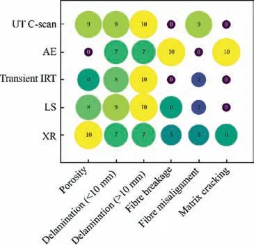
Fig. 12 Applicability of different methods (Reproduced based on the data presented in65).
4. Conclusions
The increasing interest in composites in aerospace applications is due to their superior mechanical properties over metals and on the associated weight reduction potential. The unique role of NDT techniques is to detect discontinuities of composite materials, e.g. resulting from Barely Visible Impact Damages(BVID), particularly in aerospace structures such as aircraft fuselage, tails and wings. As has been shown, the challenges associated with NDT of aerospace composites fall mainly into four groups: (a) Inspecting of large surfaces with high aspect rations and complex geometries, (b) speed of inspection, (c)detecting BVIDs and (d) three dimensional assessment of structures.
In this study, theories and case studies of six nondestructive test methods i.e.Ultrasonic Testing(UT),Acoustic Emission (AE), Eddy Current Testing (ECT), infrared thermography testing (IRT), and advanced methods of X-ray(XR) imaging techniques were thoroughly examined with respect to their applicability and limitations in evaluating the integrity of CFRP composites for the use in aerospace industry.The findings and conclusions of this study are summarized in Table 4.
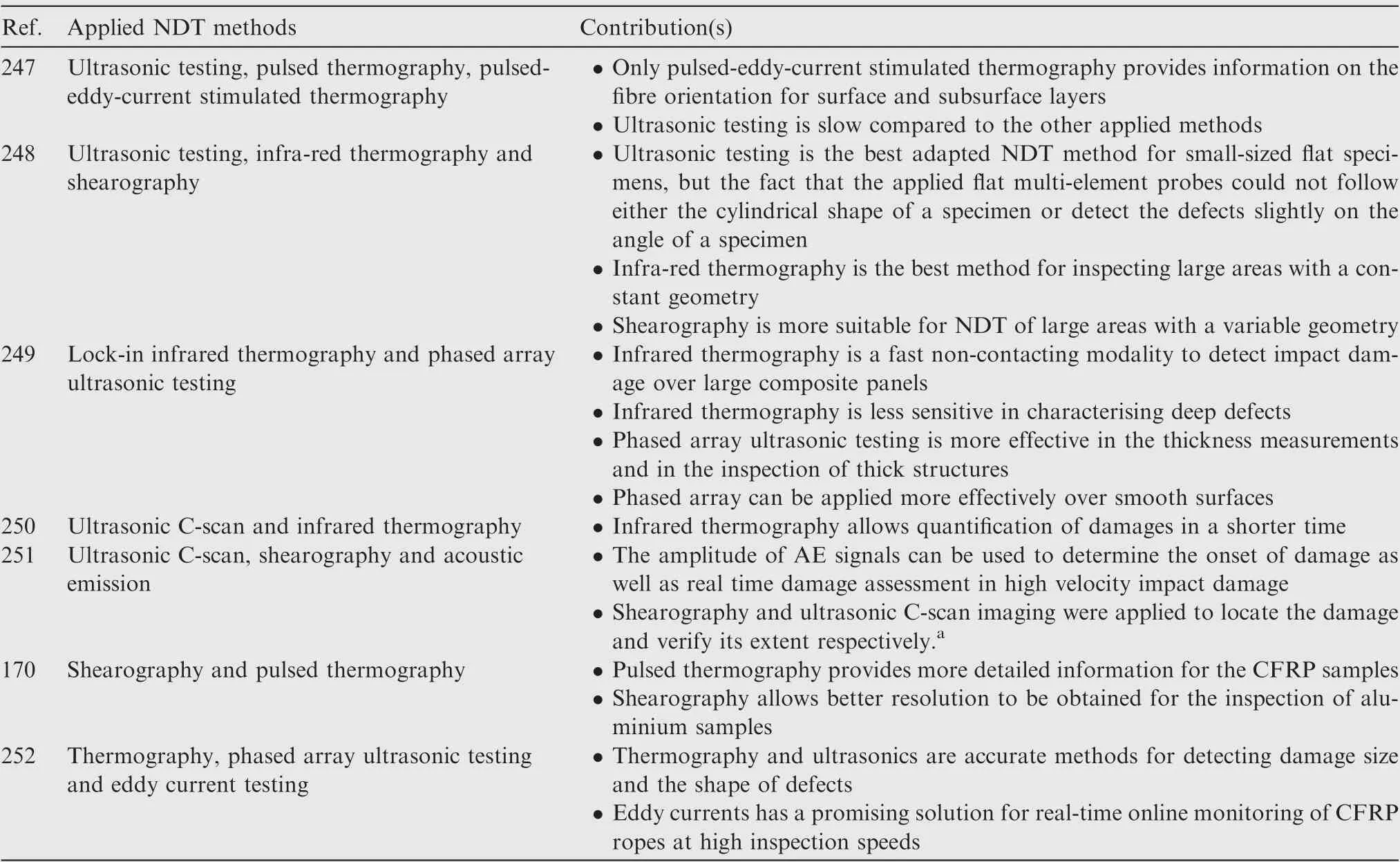
Table 3 Summary of researches on comparison of different NDT methods.
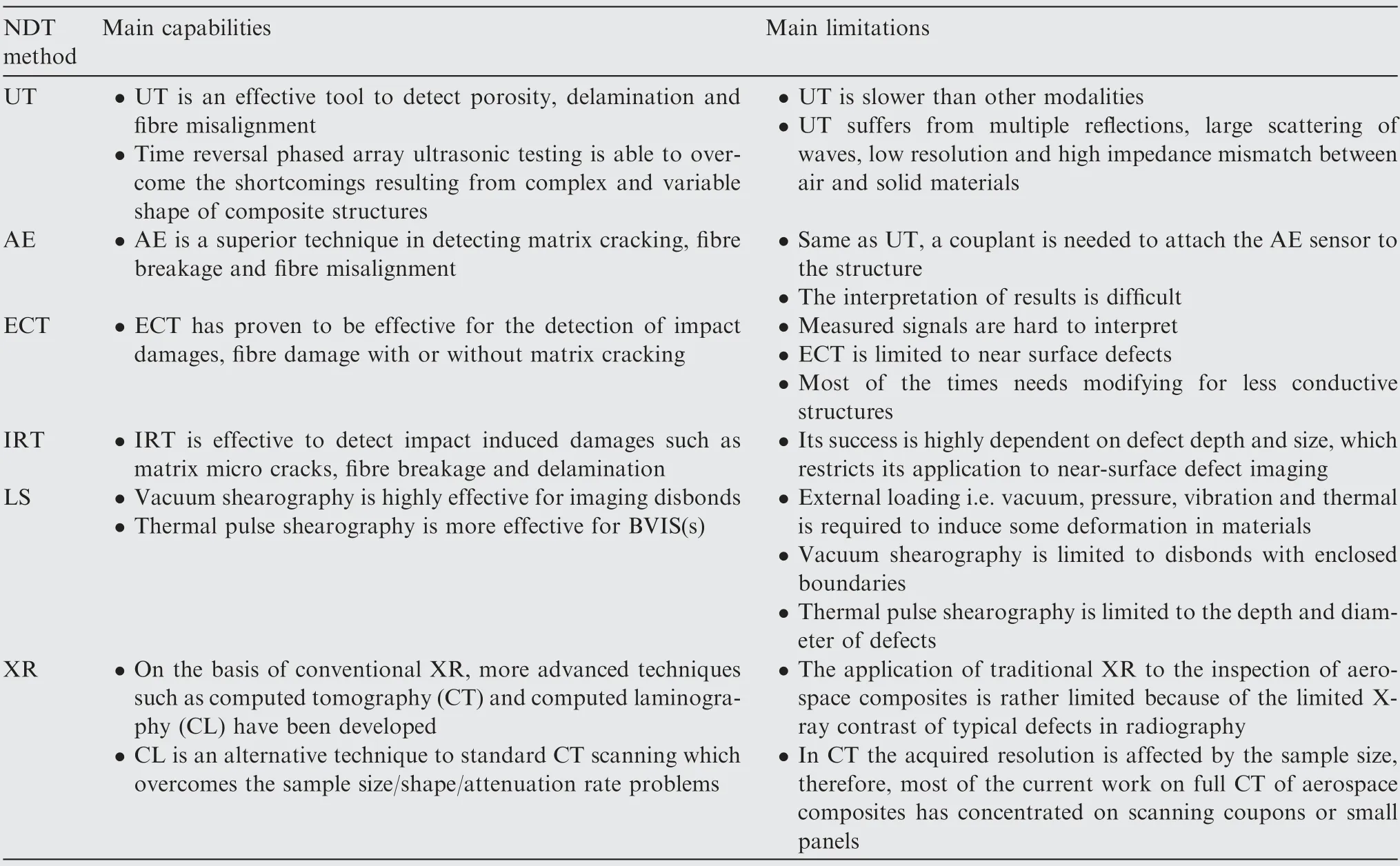
Table 4 Summary of main findings.
Acknowledgement
The authors gratefully acknowledge the support of NVIDIA Corporation with the donation of the Titan Xp GPU used for this research.This research was supported by EPSRC grant EP/R002495/1 and the European Metrology Research Programme through grant 17IND08.
 CHINESE JOURNAL OF AERONAUTICS2020年3期
- CHINESE JOURNAL OF AERONAUTICS的其它文章
- Experimental investigation on operating behaviors of loop heat pipe with thermoelectric cooler under acceleration conditions
- Investigation of hot jet on active control of oblique detonation waves
- Experimental study of rotor blades vibration and noise in multistage high pressure compressor and their relevance
- Unsteady wakes-secondary flow interactions in a high-lift low-pressure turbine cascade
- Effect of protrusion amount on gas ingestion of radial rim seal
- Optimization design of chiral hexagonal honeycombs with prescribed elastic properties under large deformation
