Improved MPEG-4 High-Efficiency AAC With Variable-Length Soft-Decision Decoding of the Quantized Spectral Coefficients
Sai Han*,Hongbing Ma,Ping Zhang,Tim Fingscheidt
1 China United Network Communications Group Company Limited,Beijing 100033,China
2 Beijing University of Posts and Telecommunications,Beijing 100876,China
3 Institute for Communications Technology,Technische Universität Braunschweig,Braunschweig 38106,Germany
Abstract: MPEG-4 High-Efficiency Advanced Audio Coding (HE-AAC)is designed for low bit rate applications,such as audio streaming in mobile communications.The HE-AAC audio codec offers a better coding efficiency since variable-length codes (VLCs)are adopted.However,HE-AAC has originally been designed for storage and error-free transmission conditions.For the transmission over bit error-prone channels,error propagation is a serious problem for the VLCs.Therefore,a robust HE-AAC decoder is desired,especially for mobile communications.In contrast to traditional hard-decision decoding,utilizing bit-wise channel reliability information,softdecision (SD)decoding has been known to offer better audio quality.In HE-AAC,the global gain parameter is coded with fixedlength codes (FLCs),while the scale factors and quantized spectral coefficients are coded with VLCs.In this work,we apply FL/SD decoding to the global gain parameter,VL/SD decoding to the parameters scale factors and quantized spectral coefficients.Especially,in order to apply VL/SD decoding to the quantized spectral coefficients,a new modified trellis representation in VL/SD decoding is proposed.An improved HE-AAC performance is clearly observed,with the support of both instrumental measurements and a subjective listening test.
Keywords: variable-length soft-decision decoding; HE-AAC; trellis representation; quantization; spectral coefficients
I.INTRODUCTION
In future mobile communication,multimedia communication is a hot research topic [1-3].Aiming at low bit rate applications,such as audio streaming in mobile communications and digital radio broadcasting,MPEG-4 High-Efficiency Advanced Audio Coding (HE-AAC)audio codec can deliver high audio quality at very low bit rates [4].It offers a better coding efficiency because of adopting variable-length codes (VLCs).However,it has been originally been designed for error-free transmission and storage conditions [5].For unreliable transmission conditions (e.g.,for applications of streaming audio over wireless networks),error propagation is a serious problem in VLCs,which leads to a low robustness of HE-AAC,even a single bit error introduces significant signal distortions [6].As a result,a robust HE-AAC source decoder is desired.
Some research has focused on increasing the robustness of HE-AAC,such as employing a forward error correction (FEC)and/or a cyclic redundancy check (CRC)[7],but with the bit stream syntax being changed.Another method is to perform an interpolation of the corrupted spectral coefficients,as a further option specified in 3GPP Technical Specification TS 26.402 [8].In this method,a binary reliability information per frame is used to distinguish corrupted or non-corrupted frame,which is a very coarse channel reliability information.Moreover,a delay of one frame is introduced.
The above methods are known as harddecision (HD)decoding,with decoder only receiving bits.On the contrary,a robust decoder can be obtained by a soft-decision (SD)decoding method [9-13].For the soft-decision (SD)decoding method,the receiver not only receives bits,but also expects bit-wise channel reliability information in [9,10].In this way,SD decoding method has been considered as a robust means for error concealment.Using the soft information in the form of log-likelihood ratios (LLRs),SD decoding can be applied to fixed-length codes (FLCs)[14,15],with speech and audio coding applications [15-18].
In addition,the use of VLCs is the main reason of low robustness in HE-AAC.Some research has focused on improving the performance of VLCs.Time-varying variable-length error-correcting codes for joint source-channel coding are introduced in [19].Based on the trellis representation and BCJR algorithm [20],SD decoding can be applied to VLCs [21,22],with audio coding applications [23].
In HE-AAC,the global gain parameter is coded with FLCs,while the scale factors and quantized spectral coefficients are both coded with VLCs.Considering the global gain,scale factors,and quantized spectral coefficients being corrupted,FL/SD and VL/SD decoding has been applied to the global gain and scale factors correspondingly in [23].However,the VL/SD decoding has not yet been applied to the quantized spectral coefficients.
The quantized spectral coefficients are coded using unsigned Huffman codebook and signed Huffman codebook [7].For the case of using an unsigned Huffman codebook,the codewords only represent the absolute values of the quantized spectral coefficients.For each non-zero quantized spectral coefficient,a number of sign bits is appended to the corresponding codewords.In that case,the traditional trellis representation as in [21-23] can not be directly applied to VL/SD decoding anymore,since only codewords are considered in that trellis representation,without additional unfixed number of bits following codewords.However,trellis representation plays an important role in VL/SD decoding,since it considers all the possible bit positions in bit stream at each symbol time.
In this paper,for the purpose of obtaining a robust HE-AAC source decoder,we apply SD decoding to all three parameters in the core AAC.This is on the basis of our previous work in [23],which applies FL/SD and VL/SD decoding to the global gain and scale factors.In addition,for applying VL/SD decoding to the quantized spectral coefficients,we propose a new modified trellis representation.Instrumental measurement and subjective listening test is both provided to evaluate audio quality.
The paper is organized as follows: Section II starts with introducing the standard HEAAC,including a brief overview,the coding of quantized spectral coefficients,and the standard error concealment in HE-AAC.Section III describes the detail of applying VL/SD decoding to the quantized spectral coefficients,including the explanation of new trellis representation,the calculation ofa posterioriprobabilities,and source symbol estimation.The simulation setup and results are presented in Section IV.Finally,some conclusions are drawn in Section V.
II.HE-AAC AUDIO CODING
2.1 Overview
The core of the HE-AAC audio coding is the AAC coding algorithm.A simplified block diagram of the AAC encoder is shown in figure 1 [23,24],including a filterbank,the determination of scale factors and quantization of spectral coefficients,and both FL and VL encoders.
The input audio signal is first transformed from the time domain to the frequency domain by a modified discrete cosine transform (MDCT)filterbank,generating spectral coefficients,withkbeing the spectral coefficient index.
Thereafter,the psychoacoustic model is used to calculate the threshold related to the maximum quantization noise just being masked by the signal energy [25].The psychoacoustic model works along with quantization and coding.The resulting threshold and (unquantized)spectral coefficientsfrom the MDCT calculation are required for the following process of quantization and coding.
Before explaining the process of quantization and coding procedure,first four terminologies used in AAC are introduced: gain value,scale factor band,scale factor,and global gain [26].In AAC,the unquantized spectral coefficientsare quantized toXkwith the help of the so-calledgain valuessfgb.For the sake of controlling the quantization noise in the frequency domain,the spectrum is divided into several groups of consecutive spectral coefficients,named asscale factor bands.Each scale factor band contains an integer multiple of four spectral coefficients.The width of each scale factor band and the maximum number of scale factor bandsBmaxare determined by the sampling frequency and the window type1As defined in Tables 4.117 (for long window type)and 4.118 (for short window type)in [7] for AAC operating at 24 kHz sampling rate..An example of the scale factor bands for a long window type with a window length of 2048 at 24 kHz sampling rate (Tab.4.117 in [7])is shown in figure 2,with sfb being the abbreviation of scale factor band.The implication of sections will be explained along with the noiseless coding further on.Moreover,for the purpose of reducing the amount of transmitted information,not all scale factor bands are transmitted.As shown in figure 2,only the scale factor bands in Sections are transmitted.The number of transmitted scale factor bandsBindicates that the spectral coefficientsfrom scale factor bandBtoBmax-1 are all 0,scale factors and quantized spectral coefficients are not transmitted.In each transmitted scale factor bandb∈ B = {0,1,…,B-1},the first (lowest)and the last (highest)spectral coefficient indices are denoted askmin,bandkmax,b2kmin,b and kmax,b are defined in Tables 4.117 and 4.118 in [7].,respectively.In figure 2,the lowest spectral coefficient index satisfieskmin,b∈ {0,4,…,960}.Additionally,each scale factor bandbshares one same gain valuesfgb,which is used to change the amplitude of all spectral coefficients in that scale factor band.Correspondingly,thescale factorof scale factor bandbis denoted assfb=g-sfgb,withgbeing the so-calledglobal gain,which is a common reference value to all scale factor bands,andsfgbbeing the so-calledgain values.
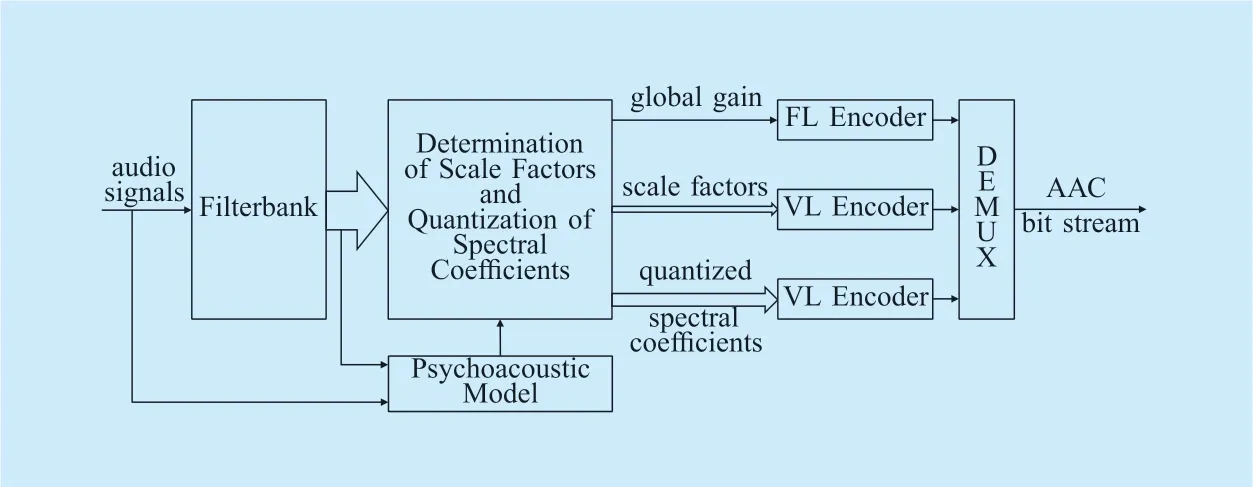
Fig.1.Simplified block diagram of an AAC encoder [23,24].

Fig.2.Description of spectral coefficients and scale factor bands (sfbs)for long window types with a window length of 2048 for AAC operating at 24 kHz sampling rate.
As shown in figure 1,the spectral coefficientsare quantized toXk[26] along with the determination of scale factorssfb.Thereafter,noiseless coding is performed to reduce the redundancy of the scale factors and the quantized spectrum.As shown in figure 1,the global gain is FL-coded by an 8 bit PCM FLC.The differential scale factors3Note that dsf 0= sf 0- g =- s fg0.dsfb=sf b-sfb-1is coded with a variable-length differential scale factor Huffman codebook.The coding process of the quantized spectral coefficients is explained in the following.
2.2 Quantized spectral coefficients
An integer multiple of four spectral coefficients is existed in each scale factor band.A number of unsigned or signed quantized spectral coefficientsXkwitht-tuples (t∈{2,4})is jointly coded by the corresponding one of the 11 different spectrum Huffman codebooks4Table 4.A.2 to Table 4.A.12 in [7]..For each spectrum Huffman codebook,whether the codebook is unsigned or signed,the largest absolute valueand the tuple sizetare defined in Table 4.132 in [7].For the unsigned codebook,based on the magnitude ofXk,or for the signed codebook,according to the value ofXk+lav,the quantized spectral coefficientsXk(in 2-or 4-tuples)are transformed to the corresponding spectrum Huffman codebook indicesic,or spectrum codewords,which is explained in detail in the following.
Based on the section length,adding the width of each scale factor band,the total number of spectral coefficients in one section is obtained and denoted as5In Ks,s refers to section.Ks.In each section,a block of spectrum Huffman codebook indicesis multiplexed,withlbeing the symbol index andBc=Ks/tbeing the block length (i.e.,the number of transmitted spectrum codebook indices).
Thereafter,the VL encoder maps each spectrum codebook indexic,lto a corresponding VL bit combination yl∈{0,1}N(ic),withN(ic)being the codeword length of the spectrum Huffman codebook indexic∈I= {0,1,… ,....} in different ranges for different spectrum codebooks (from Table 4.A.2 to Table 4.A.12 in [7]).The Huffman codewords are represented bywithbeing themth bit ofAfter demultiplexing,the unipolar bit streamis transformed to a stream of bipolar modulation symbolsby a binary phase-shift keying (BPSK),withRcbeing the total number of bits associated with the spectrum codebook indices (i.e.,spectral coefficients)in that section,being the bipolar representation of yl,and symbol ()Timplying the transpose.After transmission over a channel,the received hard-decided bipolar bit combinationis analyzed from bit position 1 toRcby the traditional VL/HD decoder,as in [23].In contrast,log-likelihood ratios (LLRs)denoting the channel reliability information are received by the VL/SD decoder.Moreover,the block lengthBcand the bit stream lengthRcwill also be required by the VL/SD decoder,where the calculation ofa posterioriprobabilities (APPs)and source symbol estimations are performed to obtain the received source symbols.
In case of encoding quantized spectral coefficient using unsigned Huffman codebooks,for each non-zero one,a variable number of sign bits is followed by a number of codewords representing absolute value [7].In other words,for the codebooks witht-tuples,a number of 0 totbits is required for the sign bits.
In the following the decoding process of the quantized spectral coefficients is explained in detail.As shown in figure 3,for each scale factor bandb,the decoding ofXkis in ascending order of frequency index fromk k=min,btok k=max,b.According to adecoder-sidedlookup table,the codewords are first transformed to the corresponding spectrum Huffman codebook indexic(assumingicis correctly received by the decoder). Thereafter,the indexicis analyzed to a 2-tuples of quantized spectral coefficients by [7]

or as a 4-tuples of quantized spectral coefficients by
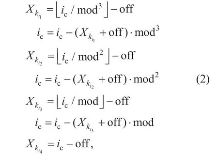
respectively,with mod = 2 ·lav + 1 and off = lav for a signed codebook,while mod = lav + 1 and off = 0 for an unsigned codebook.Note that,in (1),we havekt2=kt1+1,withMoreover,in (2),we havekt2=kt1+1,kt3=kt1+2,kt4=kt1+3,w i t h
2.3 Standard error concealment in HE-AAC
An error concealment function is defined in the AAC core decoder [8],but with a decoder delay of one frame.Various tests are included in the core decoder,which start with CRCs and end in a variety of plausibility checks.Just before the final frequency-domain-to-time-domain conversion,error concealment is applied to the received inversely quantized spectral coefficientsonce a corrupted or missing frame is indicated by a frameOK flag,or once an invalid bit stream is suggested by any of the checks.In error concealment,according to the spectral valuesof a stored last good frame,the spectral valuesof the corrupted/missing frame are replaced.Note that the stored last good frame is only updated by a good frame.For the replaced corrupted/missing frame,the signs of the spectral values are randomly determined.An interpolation is performed,if only a single frame is corrupted6Last frame (ℓ-1)is good,current playing frame (ℓ)is bad,next played (current received)(ℓ+1)frame is good..
Four different states are defined in the error concealment procedure [8]: ok (as described above),fade out,fade in,and muting.A fade out occurs if multiple consecutive frames are corrupted,the spectral values are incrementally attenuated according to the values from the last good frame.The concealment turns to muting (i.e.,the complete spectrum is set to zero)after five bad frames.Once new good frames become available,the concealment turns to muting.The process of fading in also keeps five frames.
III.VARIABLE-LENGTH SOFT-DECISION DECODING OF THE QUANTIZED SPECTRAL COEFFICIENT
Similar to [23],which applies VL/SD decoding to scale factors,in this paper,we apply the VL/SD decoding approach from [22] to spectral coefficients,with a new modified trellis representation having its roots in [21].More clearly that the VL/SD decoding approach is applied to the spectrum Huffman codebook7In this section,unless explicitly mentioned,the spectrum Huffman codebook refers to one of the 11 spectrum Huffman codebooks.indexic,producing a new received spectrum Huffman codebook indexAfterwards,based on (1)or (2),the received quantized spectral coefficientscan be obtained by replacingicby the received
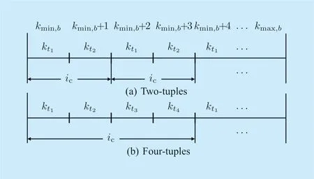
Fig.3.Analyzation of the spectrum Huffman codebook index icto the quantized spectral coefficients Xk,with (a)two-tuples and (b)four-tuples Huffman codebooks.
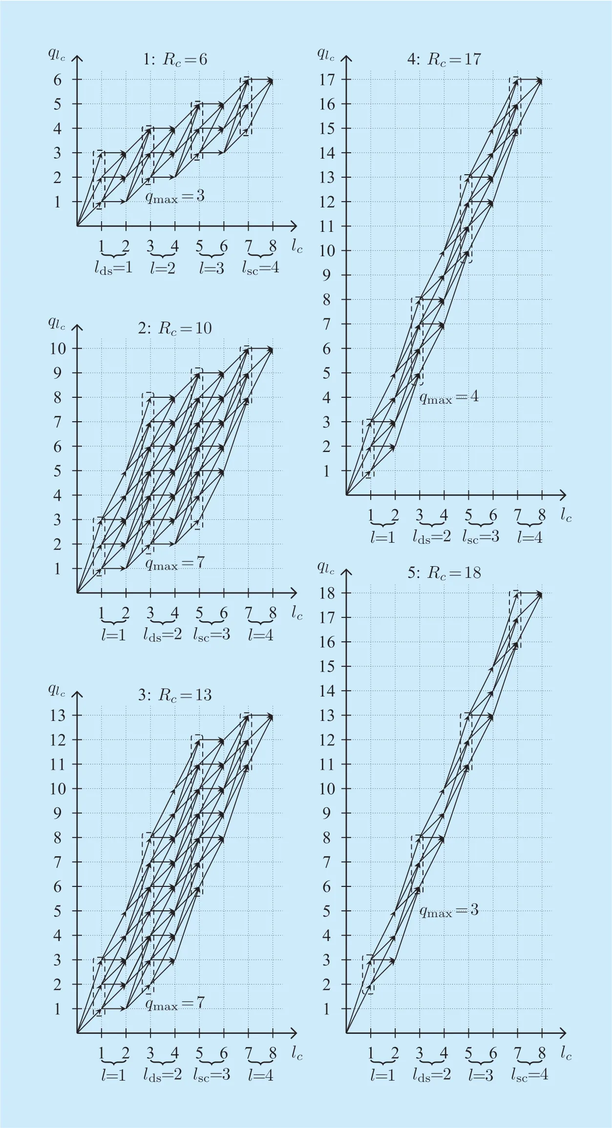
Fig.4.New modified trellis representation for the unsigned spectrum Huffman codebooks,with an example of Bc=4,t=2(Rc′′=14,l′=3),and codeword length N( ic)∈{1,2,3}.
In figure 2,the same spectrum Huffman codebook is used for all the spectral coefficients in a given section.Therefore,the application of VL/SD decoding is performed for each section,which has the same spectrum codebook.Note that different to the block length for the scale factors,which is on a frame basis [23],for quantized spectral coefficients,the block length is on a section basis.
In the following,the new trellis representation is explained in detail.
3.1 New trellis representation
A number of 0 totsign bits has also to be considered as a symbol in the new trellis representation.A new trellis representation with an example ofBc=4,t=2 is shown in figure 4,the Huffman codeword lengthN()ic∈{1,2,3}.Five cases of different total number of bitsRcin one block is depicted in figure 4.On one hand,we define that the absolute value and the corresponding sign of the quantized spectral coefficients share a sameglobalsymbol indexl= {1,2,… ,Bc}.On the other hand,considering a number of 0 totsign bits as an individual symbol,thelocalsymbol index is defined aslc= {1,2,… ,2 ·Bc}.Therefore,theoddlc(lc= 2 ·l-1)implies the absolute value,while theevenlc(lc= 2 ·l)denotes the sign of the received quantized spectral coefficients.In other words,theglobalsymbol time indexlincludes thelocalsymbol indexlcfor the absolute value andlc+1 for the sign.
HE-AAC has originally been designed for the transmission over error-free conditions,where the start and end bit positions in the bit stream of each source symbol (represented by the corresponding codeword)can be correctly localized by the decoder.In contrast,for erroneous transmission conditions,at each symbol time index,the bit positions in the bit stream at the receiver may not be correctly identified.Even single bit errors can lead to significant signal distortions,error propagation is a serious problem for VLCs.Therefore,at each time index,all the possible bit positions should be considered.This has been demonstrated in the trellis representation used in VL/SD decoding [21].
At the currentlocalsymbol indexlcwhich belongs to the currentglobalsymbol indexl,the possible positions of the last bit of VL bit combination ylcare denoted as stateqlc=ν∈Qlc=[νstart,νend].Table 1 depicts the detailed implication of the local symbol indices (absolute value or sign)and state notations.On one hand,fromevenlc(sign symbol index)tooddlc(absolute value symbol index),the state is possible to change in a range ofNm′intoNm′ax,withNm′inandNm′axbeing the minimum and maximum Huffman codeword length used in the trellis representation,respectively.On the other hand,fromoddlctoevenlc,the state can change in a range of 0 tot.
Moreover,it is found thatNm′in= max(Rc-Nmax·(Bc- 1)-t·Bc,Nmin)andNm′ax= min(Rc-Nmin·(Bc- 1),Nmax),withandrepresenting the minimum and maximum codeword length of all the Huffman codewords,respectively.
From [21,23] and figure 4,it is known that the trellis representation can be divided into three stages.But different to [23],the boundaries of three stages are discriminated only according to the number of states foroddlocal symbol indiceslc,regardless of the number of states foreven(i.e.,sign)symbol indices.In the diverging stage,the number of states inQlcincreases along withlc,the number of states inQlcremains the same in the stationary stage,and for the converging stage,the number of states decreases until reaching the known number of symbol and bits in the block (2·Bc,Rc).
In the following,we will present how to obtain the maximum number of statesqmaxforoddlocal symbol indiceslcand two stageboundariesldsandlsc8The stationary stages are in the range of [l ds,lsc]..Note that the maximum number of states forevenlocal symbol indices isqmax+t.For example,as depicted in figure 4,forRc=13,qmax=7,and the number of states forlc=4 is 8.

Table I.The definition of the global symbol index,local symbol index,and the state.

Table II.Definitions of state intervals for the diverging,stationary,and converging stages in the new trellis representation.
Step 1: An intermediate valueRc′′needs to be found,which satisfies the smallest integer value ofRcwith

The corresponding intermediatel′′is calculated by
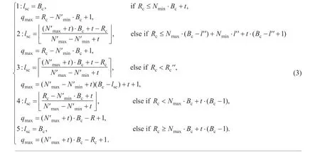
Step 2: The boundary of stationary and converging stageslscandqmaxforoddlocal symbol indices (notevenlc!)can be obtained differently as (3)shown in the top at next page.
Step 3: Afterqmaxis obtained,the boundary of diverging and stationary stagesldscan be calculated by
Step 4: Finally,the state intervals for the three stages can be found in Table 2.
3.2 A posteriori probabilities
The core of the VL/SD decoder is to calculate thea posterioriprobabilities (APPs),which are further used for source symbol estimation.The APP is obtained based on the modified BCJR algorithm from [6,21,22].Using the new trellis representation,the local symbol indexlcis considered in the APPs calculation.Therefore,the block length 2·Bc,the bit stream lengthRc,and the LLRs is required in VL/SD decoding.
At symbol timelc,the APPs of a possibly transmitted VL bit combination ylc= y(ic),given the received bit stream yˆ1Rcis calculated by

with the forward probabilityαlc-1(μ)=backward probabilityandγlc(ic,μ,ν)=I n a ddition,the received bit stream from bit positionμtoνis denoted asThe stateμis an element of state setQlc-1at the previous symbol timelc-1,whileν∈Qlcdenotes the current symbol timelc,respectively.The constant

used to normalize the sum over the APPs to one.
1)Forward recursion:The forward recursion is performed by

with the initial valueα0(0)1= ,and

which includes achannel termand asource probability distribution term.
(1)Channel Term
Assuming a memoryless channel,the channel term,which represents the probability of the received bit streamgiven a probably transmitted quantizer bit combination ylc= y(ic),can be obtained by the conditional bit probability


(2)Source Probability Distribution Term
The latter term of the right-hand-side of (6)implying thesource probability distribution termcan be obtained either with the zerothordera prioriknowledge (AK0)or the firstordera prioriknowledge (AK1),by modeling the quantized symbols either as a zeroth-order Markov process,or as a first-order Markov process,respectively.Due to the fact that there are more spectral data than scale factors,and the SD decoding is applied to a number of 10 spectrum Huffman codebooks as well,compared to the VL/SD decoding of scale factors,the complexity for quantized spectral coefficients is significantly increased.Therefore,in this work,only the VL/SD decoding with AK0 model is adopted for the quantized spectral coefficients,since AK1 term introduces more computations.
Using a large database,thea prioriknowledge is obtained in the training process in advance.Counting and normalizing the occurrence frequencies of different pairs of quantizer output symbols,the AK0 term can be calculated by

Thesource probability distribution termcan then be computed by

with the normalization (equal to one in the diverging stage)

Note that withic∈I,not all the transitions fromare available both in the stationary and the converging stages.Therefore,C′()μin (11)is not always equal to one.
2)Backward Recursion: Considering the statesν∈Qlcat the current symbol timelcandν′∈Qlc+1at the next symbol timelc+1,the backward recursion is processed as

with the initial value ofβbeingβ2c·Bc()1R= and

including achannel termand asource probability distribution term.
In analogy to the forward recursion,thechannel termis computed by

Thesource probability distribution termcan be obtained by
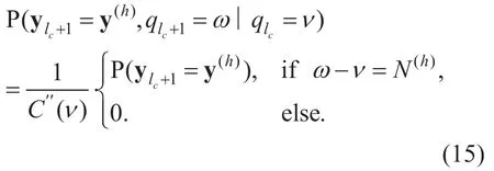
Taking the special cases of stationary and converging stages into account,the normalization is performed as

In addition,different to [23],which only have one scale factor codebook in the VL/SD decoding.In this work,on the one hand,the spectrum Huffman codebook is used for theoddvalues oflcto calculate the APPs for the absolute values of the quantized spectral coefficients.On the other hand,an additional different codebook is used forevenlcto compute the APPs for the corresponding sign.As mentioned in Section 2.2,the sign bits are only valid for non-zero quantized spectral coefficients,a number of 0 totbits should be defined in the sign codebook.The sign codebook is shown in Table 3,witht=2,the codebook size10The codebook size of the sign codebook for t=4 is 81.being 9.Herein,x implies no sign bits at the corresponding position.More specifically,the received quantized spectral coefficient=0 (no sign bits)and>0 (sign bit 0)is denoted by x0;<0 (sign bit 1)and=0 (no sign bits)is denoted by 1x.Note that when the sign codebook index is 0 (xx: no sign bits),the channel term in (7)is 1.
In Table 3,the reason of some codebook indices sharing the same codewords (e.g.,codebook indices 1 and 3,or 2 and 4)is due to the fact that,the number of sign bits and the position of sign bits are determined by the absolute value.In order to distinguish that,for the APP calculation of the sign symbol,instead of considering all sign codebook indices,based on the corresponding estimated absolute values,the actually used sign codebook indices are taken into account,which are limited to a small range.This can be explained more clearly witht=2 as an example.If onlyis non-zero,the codebook indices 1 and 2 are taken into account,while codebook indices 3 and 4 are used once onlyis non-zero,etc.
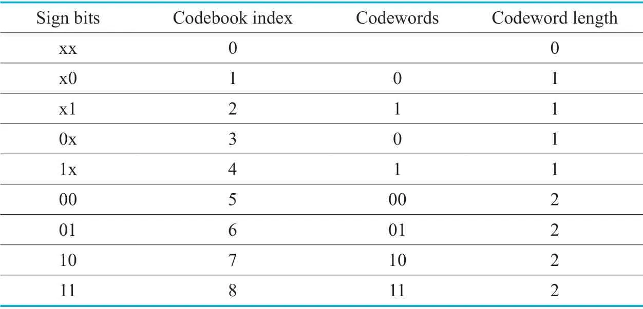
Table III.The sign codebook for 2-tuples of quantized spectral coefficients.
3.3 Source symbol estimation
After the calculation of the APPs,based on the corresponding codebook,the received Huffman codebook indexis estimated.
It is found that compared to MMSE estimation,a better performance can be provided by using the maximuma posteriori(MAP)estimator:

Since the estimated value (i.e.,the received Huffman codebook index)is further divided and transformed to new received quantized spectral coefficients by (1)and (2),replacingicbyFor unsigned Huffman codebook,MAP estimation is applied to both the absolute value and the sign.Note that it is applicable to the signed Huffman codebook as well.
Note that for the escape (ESC)Huffman codebook (spectrum Huffman codebook 11),0 or 25·+np(np∈ …{0,1,,8})bits are followed by the sign bits additionally.Considering the escape_sequence as a symbol index in the trellis representation,a codebook size of 8177 words would be required.Although it is not necessary to store the whole codebook,still a number ofnp+4 bits (with the maximum value being 12)is required for the escape_sequence (12-bit codebook).The complexity of VL/SD decoding for escape (ESC)Huffman codebook would be dramatically increased.As a result,VL/SD decoding is not suggested and adopted for the spectrum Huffman codebook 11.
IV.SIMULATION SETUP AND RESULTS
The performance of HE-AAC with HD and SD decoding is compared in this section.In this work,the bits related to the values of global gaing,scale factorssf,and quantized spectral coefficientsXk,are distorted by the erroneous channel.All the other bits in HE-AAC bit steam are assumed to be received without error (i.e.,with the correct bit positions in the whole HE-AAC bit stream).This implies that the knowledge about which spectrum Huffman codebook to be used for each scale factor band is known correctly,and the SBR part is non-corrupted too.
4.1 Simulation setup
Focusing on low bit rate applications (e.g.,mobile audio streaming),we adopt HE-AAC v1 (including AAC and SBR)operating at 24 kbps11One example of application is a DAB+ radio sport station in Melbourne,Australia [29].with 48 kHz sampling rate and monophonic audio signals.
A number of 15 monaural music pieces with a total length of 89 min is used in the training process.For testing,a number of 10 monaural fractions of other music pieces with a total length of 68 s is adopted.The audio data covers excerpts from classical music pieces with a motion-picture soundtrack with music and effects,and with different instruments (organs,strings,brass and percussion instruments).In addition,all signals are 16 bit pulse-code modulated with 48 kHz sampling rate and have been normalized to -26 dBFS (decibels relative to full scale).
1)Channel Model Setup:The Gilbert-Elliott (GE)channel model with additive white Gaussian noise (AWGN)noise and the AWGN channel model are adopted in the simulations.A GE channel is a time-variant channel with two states: good (G)and bad (B).The state changing process is considered as a first-order Markov process.Starting with a good state,the transition probability from good to bad is denoted asP,while the one from bad to good is identified byQ.For the good state,theEb/N0|goodis 10 dB (i.e.,non-perfect transmission even in the good state),while for the bad state,Eb/N0|badis varied in a range from 5 to 10 dB.The simulation was set up for the purpose of provoking the future of more efficient media transmission,where frames are not lost but only a few bit errors occur.For any given test condition,each audio file is transmitted over five different channel realizations,in order to increase the reliability of the performance measurements.
In addition,the performance of using the error concealment in 3GPP Technical Specification TS 26.402 [8] is also compared in this work.The frameOK flag distinguishing bad frames (bad channel state)and good frames (good channel state)is known by the decoder as an additional input file to the decoder.
2)Audio Quality Measurement:The audio quality is measured by both instrumental measurement and subjective listening test.On the one hand,the parametric coding tools (e.g.,SBR)are included in the HE-AAC,which depart from the waveform coding,instead of the instrumental measurement [4],a reliable subjective listening test has to be used for assessing audio quality.On the other hand,subjective listening tests are time-consuming.Considering above,only some simulation results are evaluated by a subjective listening test,all the simulations are performed with the instrumental measurement.As presented in [23],in error concealment experiments,audio quality is in fact better reflected by the global SNR instead of by the perceptual evaluation of audio quality (PEAQ)[30].Therefore,only global SNR is adopted for instrumental measurements in this work.For the subjective listening test,the MUlti Stimulus test with Hidden Reference and Anchor (MUSHRA)[31] is used.MUSHRA is known to be more suitable for evaluating medium and large impairments [31].A number of 20 subjects participated in the listening test,which includes 10 experiments corresponding to 10 different audio files.In total 4 subjects are removed before analyzing the results,since they have graded 2 or 3 reference files with a score lower than 90.Therefore,finally a remaining number ofNL=16 listeners and a number ofNF=10 audio files is used for each test condition.Moreover,a MATLAB interface MUSHRAM [32] is adopted for the subjective listening test,with a laptop PC,an external sound card (FocusriteScarlett6i6),and a high-quality headphone (AKGK271MKII).
For the MUSHRA listening test,starting with a training phase,the listeners are familiar with all the sounds experienced during the test.In the evaluation phase,compared to the reference sound,the listeners have to grade all the test sounds including one hidden reference,two hidden anchors,and all the sounds under different test conditions (e.g.,HD and SD decoding).The hiddnen reference should be found and scored as 100.Both two hidden anchors are low-pass filtered from the reference signal,with the cut-off frequency being 3.5 kHz (low-range anchor12The 3.5 kHz low-pass filter meets the requirement of the maximum pass band ripple being ±0.1 dB,the minimum attenuation at 4 kHz being 25 dB,and the minimum attenuation at 4.5 kHz being 50 dB [31].)and 7 kHz (midrange anchor),respectively.
In the MUSHRA listening test,the scores varying from 0 to 100 are assigned to 5 equally distributed intervals: bad,poor,fair,good,and excellent,with 20 scores for each interval.
For the subjective listening test,the GE channels withP=0.9,Q=0.1 andE b/N0|bad∈ {5,6.5} dB with the bit error probability being 3.7 ·10-3and 8.7 ·10-4are selected13The BER of the typical bad and good channel conditions is 10-3 and 10-4,respectively [33]..Theis calculated by

Herein,BERGand BERBare correlated to the respective SNRsEb/N0|goodandEb/N0|badfor the good and bad channel state.Moreover,we have[34].
4.2 Results and discussion
In order to compare the performance of HD and SD decoding,two different experiments are performed:
·The bits of a single parameter (i.e.,quantized spectral coefficients)are distorted separately.
·The bits of all three parameters (global gain,scale factors,and quantized spectral coefficients)are distorted.
The results of HD decoding is represented by HD,while SD decoding with zeroth-order and first-ordera prioriknowledge is denoted by AK0 and AK1,respectively14Note that HD,SD,AK0,and AK1 imply the decoding method only for the respective distorted one parameter or three parameters in the different experiments..The results of error concealment is described by EC.
1)Single Parameter Distorted:The simulation results of HE-AAC transmission over an AWGN channel,with only the parameter quantized spectral coefficients being corrupted are shown in this part.
As mentioned in Section 3.3,VL/SD decoding is not adopted for the quantized spectral coefficients with the spectrum Huffman codebook 11.For the sake of a fair comparison between HD and SD decoding,the bits of the global gain,the scale factors,and the quantized spectral coefficients with spectrum Huffman codebook 11 are assumed to be error-free.
Note that,HD and SD suggest the decoding method for the specific spectrum Huffman codebooks.Moreover,for the transmission over an AWGN channel,the EC always turns to complete muting and therefore not listed here.
In addition,because of the new modified trellis representation for the unsigned spectrum Huffman codebooks,it is interesting toobserve the performance when only the bits of the signed codebooks (i.e.,spectrum Huffman codebook 1,2,5,6)are erroneous (i.e.,without new modified trellis representation).The corresponding global SNR results of HD and SD are shown in Table 4(a).A slight SNR improvement of up to 1.05 dB is observed in Table 4(a).WhenE b/N0= 0 dB,HD even outperforms SD.One reason for that is the small redundancy; another possible reason is that different to the global gain or scale factors,which take the estimated values directly or add them to some numbers,the estimated spectrum Huffman codebook indextakes a further step (divided into a number of 2 or 4 received quantized spectral coefficients),which may not be able to lead to values closer to the original correct values,especially that the quantized spectral coefficients are not unsigned values.
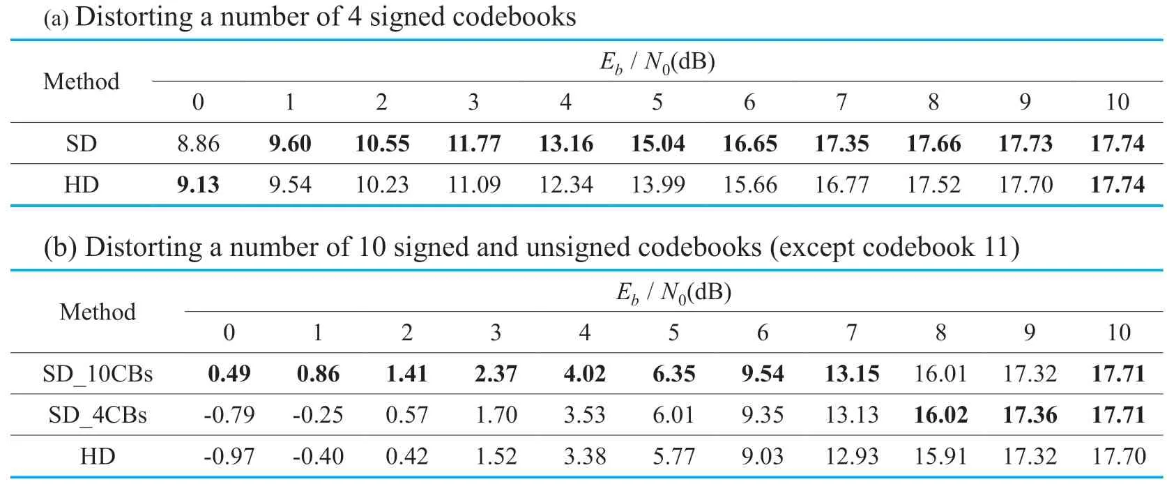
Table IV.Global SNR (dB)results for HE-AAC transmission over an AWGN channel,with only corrupted quantized spectral coefficients.
Moreover,distorting bits of 10 spectrum Huffman codebooks,the global SNR results are shown in Table 4(b),with SD_4CBs implying VL/SD decoding for a number of 4 signed codebooks,and SD_10CBs representing VL/SD decoding for a number of 10 codebooks including both unsigned and signed codebooks,respectively.In comparison to the best of HD and EC15The SNRs of EC are always 0.,the SNR of SD decoding is improved by up to 0.99 dB.Moreover,comparing the results of SD_10CBs and SD_4CBs,the maximum SNR difference is 1.28 dB,which indicates the superiority of using the new modified trellis representation in this work.
2)Three Parameters Distorted:Distorting three parameters global gain,scale factors,and quantized spectral coefficients,the simulation results of the HE-AAC transmission over a GE channel are shown in the following:
·SD decoded global gain and scale factors,HD decoded quantized spectral coefficientswithout spectral side information

Table V.Global SNR results for HE-AAC transmission over a Gilbert-Elliott channel with Eb / N0|good=10dB.The global gain,scale factors,and quantized spectral coefficients are being corrupted.The quantized spectral coefficients are HD-decoded.

Table VI.Global SNR (dB)results for HE-AAC transmission over a Gilbert-Elliott channel with Eb / N0|good=10dB.The global gain,scale factors,and quantized spectral coefficients are being corrupted,with spectral side information.
·SD decoded global gain,scale factors,and SD decoded quantized spectral coefficients with spectral side information
·SD decoded global gain,scale factors,and SD decoded quantized spectral coefficients with spectral side information,spectrum Huffman Codebook 11 assumed error-free(1)HD Decoded Quantized Spectral Coefficients (Without Spectral Side Information)
In this part,the parameter quantized spectral coefficients is HD decoded,without spectral side information (i.e.,total number of bits in each section).As shown in Table 5,forPQ= =0.9,0.1,compared to HD/EC,using three different SD decoding methodsg_AK0/dsf_AK0,g_AK1/dsf_AK0,g_AK1/dsf_AK1,the performance has been enhanced,with the SNR gain andE b/N0|badgain up to 2.9 dB and 0.56 dB,respectively.Comparing the three methods,the SNR difference betweeng_AK1/dsf_AK0 andg_AK0/dsf_AK0 is up to 0.12 dB,while the maximum performance gap betweeng_AK1/dsf_AK1 andg_AK1/dsf_AK0 is only 0.02 dB.Considering this minor improvement and complexity by using VL/SD decoding with AK1,g_AK1/dsf_AK0 is assumed as the best option for SD decoding,which can increase the SNR by up to 2.88 dB,compared to HD/EC.As a result,the methodg_AK1/dsf_AK0 is chosen for the transmission over a GE channel withP= 0.62,Q=0.38.The SNR gain andEb/N0|badgain between SD decoding and HD/EC reach up to 2.58 dB and 0.41 dB,respectively [23].
(2)SD Decoded Quantized Spectral Coefficients With Spectral Side Information
As mentioned in Section III,the side information (i.e.,total number of bits in each section)should be known and required by the VL/SD decoding of the quantized spectral coefficients.In order to have a fair comparison between HD and SD decoding,the side information of the quantized spectral coefficients should be considered by both methods.For the sake of observing the performance improved by purely applying SD decoding to the quantized spectral coefficients,two different SD decoding methods are distinguished:g_AK1/dsf_AK0/ Xk_AK0 andg_AK1/dsf_AK0/ Xk_HD in Table VI.
Firstly,for both GE channels,on the one hand,the HD decoding approach with the known spectral side information overtakes the HD decoding without side information in Table 5.On the other hand,the EC performance remains the same as expected.
Secondly,compared to HD/EC,usingg_AK1/dsf_AK0/ Xk_HD,the SNR in Table 6 can be improved by up to 3.74 dB and 3.08 dB (compared to 2.88 dB and 2.58 dB in Table 5)forP=0.9 andP=0.62,respectively.The correspondingEb/N0|badgain reaches up to 0.65 dB and 0.5 dB (compared to 0.56 dB and 0.41 dB in Table 5).However,compared tog_AK1/dsf_AK0/ Xk_HD,usingg_AK1/dsf_AK0/ Xk_AK0,the SNR is again improved by a maximum of 0.4 dB whenP=0.9 and 0.35 dB whenP=0.62.Moreover,comparingg_AK1/dsf_AK0/ Xk_AK0 and HD/EC,the SNR is increased by 4.14 dB and 3.39 dB forP=0.9 andP=0.62,respectively.It seems that applying SD decoding to the quantized spectralcoefficients,there is a slight improvement.However,the bits associated with the Huffman codebook 11 which represent the large quantized value are always HD decoded,which may leads to some effect on the results.

Table VII.Global SNR (dB)results for HE-AAC transmission over a Gilbert-Elliott channel with Eb / N0|good=10dB.The global gain,scale factors,and the bits of quantized spectral coefficients with Huffman codebook 1 to 10 are being corrupted,with spectral side information.
(3)SD Decoded Quantized Spectral Coefficients With Spectral Side Information,Spectrum Huffman Codebook 11 Assumed Error-Free
For the purpose of excluding the influence of HD decoded large quantized values with spectrum Huffman codebook 11,and investigating the improvement by SD decoding with new trellis representation purely,similar to Table 6,the bits of the spectrum Huffman codebook 11 are assumed error-free in this part.As shown in Table 7,the SNR gain and theEb/N0|badgain between usingg_AK1/dsf_AK0/ Xk_AK0 and HD/EC is up to 6.63 dB and 1.25 dB,while the corresponding values between usingg_AK1/dsf_AK0/ Xk_HD and HD/EC is 6.05 dB and 1.2 dB.The maximum SNR difference between using the method ofXkwith AK0 andXkwith HD is 0.61 dB.
To sum up,we can state that applying FL/SD decoding with AK1 to the global gain and VL/SD decoding with AK0 to the scale factors,the performance can be dramatically improved for the HE-AAC transmission over erroneous channel conditions.A further slight improvement can be obtained by adopting VL/SD (AK0)decoding to the quantized spectral coefficients.
3)Subjective Listening Test Results:The subjective listening test results are depicted in figure 5,with mean MUSHRA score (the center point in the bar)and the associated 95% confidence interval (the bar)of the reference,anchor,and test signals.As presented in [35],a more complete comprehension of the performance comparison between different test conditions should be provided by the individual results of each audio file (i.e.,file 1 to file 10)and the average results considering all the audio files (the column depicted as "all" in figure 5),separately.
The MUSHRA scores of the reference and two anchors are drawn in the first plot.The listening test results of two parameters (global gain and scale factors)and three parameters (global gain,scale factors,and quantized spectral coefficients)being corrupted are depicted in the second and third plot,respectively.
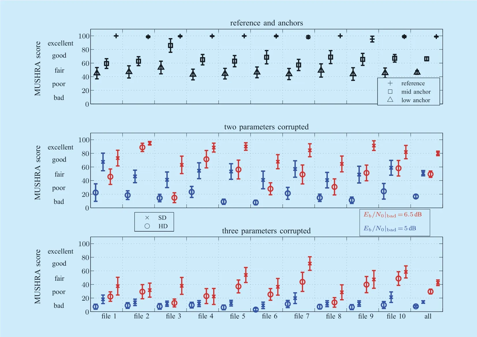
Fig.5.MUSHRA results with the mean and the associated 95% confidence interval.
A GE channel withPQ= =0.9,0.1 is adopted in both plots.HD implies that the corresponding two or three parameters are HD-decoded.Taking the tradeoffs of the performance,complexity,and the amount of side information into account,optimal SD decoding methods are adopted in the listening test,with SD denotingg_AK1/dsf_AK0 in the second plot,whileg_AK1/dsf_AK0/ Xk_HD without spectral side information in the third plot,respectively.
For all test files and test conditions,it can be clearly seen that the mean score of SD always outperforms HD.On the one hand,some overlaps of the 95% confidence intervals are observed: For files 2 and 4 if two parameters are corrupted,and for all the files when three parameters are corrupted.On the other hand,considering all audio files,for a given test condition,the average result indicates no overlap of the 95% confidence interval between HD and SD.Therefore,it can be stated that it is sensible to study the mean score for all the audio files.Therefore,the mean MUSHRA score of all the test files is discussed in the following.
On the one hand,when two parameters are corrupted,the MUSHRA score gain between SD and HD reaches 34.19 and 30.56 forEb/N0|bad=5 dB and 6.5 dB,respectively.Correspondingly,the audio quality is significantly improved from bad to fair,and from fair to good.On the other hand,for the case of three corrupted parameters,the performance improvement is hardly noticeable.WhenE b/N0|bad=5 dB,the score is only increased by 6.41,the quality of both HD and SD remains bad.However,forEb/N0|bad= 6.5 dB,using SD decoding method,the audio quality can be improved from poor to fair,with a increase of 12.94.It can be stated that the subjective listening test results are consistent with the SNR results presented in Table 5.This further supports the observation that the audio quality correlates to the global SNR measure quite well.
V.CONCLUSIONS
In this paper,we apply fixed-length soft-decision decoding to the global gain and variable-length soft-decision decoding to the scale factors and quantized spectral coefficients,proposing a robust MPEG-4 High-Efficiency Advanced Audio Coding (HE-AAC)decoder.In addition,since the quantized spectral coefficients with unsigned spectrum Huffman codebooks include sign bits,which are appended to the corresponding codewords,considering both Huffman codewords and sign bits,a new modified trellis representation is newly proposed in this work.Supporting by both instrumental measurement and subjective listening test,the simulation results demonstrate that the audio quality can be significantly enhanced by using SD decoding.The global SNR has been improved by up to 4.14 dB if the bits of three parameters are corrupted.In addition,on a 100-point MUSHRA scale,the score is improved by up to 34 points using SD decoding.In comparison to the error concealment in 3GPP TS 26.402,using our proposed approach,not only the audio quality can be dramatically improved,but also no extra delay is introduced.
- China Communications的其它文章
- Distributed Optimal Control for Traffic Networks with Fog Computing
- A Sensing Layer Network Resource Allocation Model Based on Trusted Groups
- New Identity Based Proxy Re-Encryption Scheme from Lattices
- A Real Plug-and-Play Fog: Implementation of Service Placement in Wireless Multimedia Networks
- TVIDS: Trusted Virtual IDS With SGX
- Application of Neural Network in Fault Location of Optical Transport Network

