Hybrid Precoding for mmWave Massive MIMO Systems with Different Antenna Arrays
Qingfeng Ding*,Yuqian DengXinpeng GaoMengxia Liu
1 School of Electrical and Automation Engineering,East China Jiaotong University,Nanchang 330013,China
Abstract: In this paper,the performance of hybrid precoding is investigated for mmWave massive MIMO systems with different antenna arrays.The hybrid precoding with partially connected architecture (PCA)is adopted.The spectral efficiency (SE)and received energy efficiency (EE)are investigated by considering four types of antenna arrays,including uniform linear array (ULA),uniform rectangular planar array (URPA),uniform hexagonal planar array (UHPA),and uniform circular planar array (UCPA),respectively.We focus on analysis at the antenna response vector and utilize the idea of orthogonal matching pursuit algorithm to seek the optimal hybrid precoder.Furthermore,the trade-off of precoding architectures is studied between SE and received EE.Simulation results show that if the uniform planar array antenna is more concentrated,the SE and receive EE will be higher.Considering SE and received EE,the performance of planar arrays outperform linear array.There exist different optimal radio-frequency chain numbers to maximize the SE for planar array and linear array.In addition,the PCA can achieve relatively higher received EE while the SE is close to the fully connected architecture and the full digital architecture.
Keywords: massive MIMO; mmWave; hybrid precoding; array antenna; spectral efficiency
I.INTRODUCTION
In the future of 5G wireless communications,millimeter-wave (mmWave)massive multiple-input multiple-output (MIMO)has been considered as a promising candidate technology,as it can address the challenge of bandwidth shortage and achieve higher spectral efficiency (SE)[1-3].However,in classical MIMO systems,full digital precoding requires that each transmit antenna of the base station (BS)be equipped with a radio-frequency (RF)chain [4,5].When it comes to massive MIMO systems,this leads to high hardware complexity and excessive power consumption [6].
In order to reduce the number of required RF chains,hybrid precoder structures that consist of both digital precoder and analog precoder has been recently proposed [7-9].For systems with a planar array,the hybrid beamforming design is formulated as a sparse reconstruction problem,and then the orthogonal matching pursuit (OMP)algorithm is applied to obtain the optimal hybrid precoders and combiners for fully connected architecture (FCA)[7].Inspired by [7],a hierarchical idea which is utilized to design the hybrid precoder for partially connected architecture (PCA)based systems with uniform linear array (ULA)in [8],where the precoder design includes two levels.Furthermore,considering the PCA and FCA,the SE is analysed utilizing unified heuristic to design hybrid precoder for a single-user MIMO system in [9].
For massive MIMO systems,different antenna arrays have significant influence on the achievable SE [10,11].For ULA,uniform planar array (UPA),and uniform circular array (UCA)introduced in [10],achievable sum-rate is investigated in a realistic finite-dimensional channel model.In [11],the steering vector and array factor are investigated by considering uniform rectangular planar array (URPA),uniform hexagonal planar array (UHPA),and uniform circular planar array (UCPA),whose achievable SEs are investigated in a 3-dimensional massive MIMO systems.Further studies on the different geometrical shapes of antenna array will become more practical.
The focus on this paper is to investigate the SE and the received energy efficiency (EE)for hybrid precoding in mmWave massive MIMO systems with ULA,URPA,UHPA,and UCPA,and then to research the performance of different precoding architectures including the FCA,PCA and the full digital architecture (FDA).Partially connected structure of hybrid precoding is adopted and the array response vectors are analysed to study the antenna array gain for four types of antenna arrays.The maximizing SE expressions with digital precoding and analog precoding are derived.Finally,the performance of different antenna arrays is compared by the proposed hybrid precoder design,which is by utilizing the idea of OMP.The main contributions of this paper are summarized as follows.
● We adopt four types of antenna arrays,namely ULA,URPA,UHPA,and UCPA,and derive tractable antenna array response vector expression.The simulation of normalized beam pattern and physical characteristics reveal the performance of the four types of antenna arrays.
● Different from the previously published work in [7] which only consider a single ULA,our works take into account four types of antenna arrays.By utilizing the different antenna array vectors and the ideal of OMP,we research hybrid precoding with different antenna arrays and simulation shows that the performance of UHPA is best.
● We analyse the trade-off between SE and received EE to determine the most efficient precoding strategy for different precoding architectures with the ULA when the number of antennas increases.Our results show that hybrid precoding with PCA and FDA are the most energy-efficient and spectral-efficient solutions,respectively.
The rest of the paper is organised as follows.In Section II,we introduce the model of downlink mmWave massive MIMO systems.In Section III,the array response vectors are derived for different antenna arrays.In Section IV,the hybrid precoders are designed with different antenna arrays in the partially connected structure.The simulation results of beam pattern are performed for different antenna arrays,and then the SE and the received EE of hybrid precoding are compared with the four types of antenna array in Section V.Finally,conclusions are drawn in Section VI.
Notation: In this paper,we use upper and lower case boldface to denote matrices and vectors,respectively.E[·] denotes the expectation; (·)H,(·)T,(·)-1,|·|,and ||·||Fdenote the conjugate transpose,transpose,inversion,absolute operator,and Frobenius norm.Finally,Inrepresents then-order unit matrix.
II.SYSTEM MODEL
2.1 Signal model
A narrowband single-user downlink mmWave massive MIMO systems based on the PCA shown in Figure 1.The BS is equippedNRFindependent RF chains andMantennas with ULA,URPA,UHPA,and UCPA.
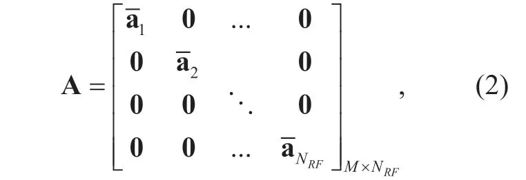
The data streamsNSin baseband are precoded by the digital precoderThen the data streams pass through RF chains,followed by the corresponding analog precoder A ∈CM×NRFat the analog domain,whose elements have the same amplitude [12,13].And each data stream is transmitted by antenna array.The received signal can be represented as

where y=[y1y1… y1]Tis the received signal,Kis the number of antennas employed at the user,andPindicates the average received power.H∈CKM×denotes the channel matrix,which satisfiess∈CNS×1denotes the transmit signal such thatn is the noise vector,which follows a complex Gaussian distribution,denotes the hybrid precoding matrix which satisfies W=AD.The hybrid precoder W satisfiesto meet the total power constrain at BS [18].A can be represented as
2.2 Channel model
In this paper,a clustered channel model is adopted based on the extended Saleh-Valenzuela model in [19] to capture the characteristics of mmWave massive MIMO channels as

whereLis the number of effective channel paths between BS and user.σr~(0,σ2l)is the gain of thel-th path.are the azimuth (elevation)angles of departure and arrival (AODs/AOAs),respectively.Assuming the antenna array of the receiver is same as BS,which employs ULA,UHPA,UCPA,and URPA.Four types antenna array response vectors Ft(·)at the transmitter are mainly studied in the next section.
III.ANTENNA ARRAY RESPONSE VECTOR ANALYSIS
In this paper,we adopt four types of antenna arrays of ULA,URPA,UHPA,and UCPA in Figure 2.In order to analyse the channel characteristics under different antenna arrays,we start by concentrating on the analysis of the antenna array response vectors with respect to different antenna array configurations,which will be respectively derived and discussed in the follow subsections.
3.1 ULA
For aM-elements ULA in the horizontal,the array response vector of ULA can be written as [20]

whereμ=2π/λandλdenotes the signal wavelength,anddis the antenna spacing.
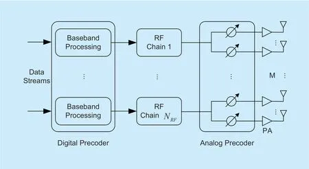
Fig.1.PCA of the hybrid precoding in mmWave MIMO systems.

Fig.2.An illustration of four types 2D antenna array configurations.
3.2 URPA
An URPA is composed ofMxandMyantenna elements in the horizontal and vertical directions,respectively.Further,for aMURPA=Mx×Myantenna elements of URPA,the array response vector of URPA can be represented by
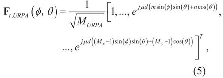
where 0≤m≤Mxand 0≤n≤My.
3.3 UHPA
The antenna in UHPA is evenly distributed among each hexagonal ring and the number of antenna element on then-th hexagon ring is 6n.The total number of antenna elements withVhexagon rings can be derived asFor aM-element UHPA in the horizontal and vertical direction,the inter-element spacing isdxanddh,respectively,and each row can be considered ULA whose the array response vector considering of even and odd rows can be respectively expressed as [21]
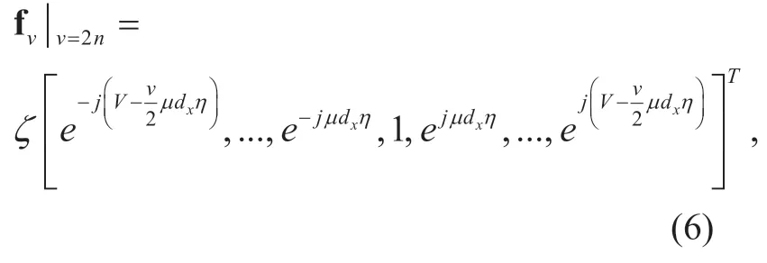
and


3.4 UCPA
Each antenna in UCPA is assumed uniformly distributed over the circle ring.The number of antennas on each circle is 6nand the total number of antenna elements withCcircle rings isThe array response vector of UCPA whose circle rings' number isncan be given as

wherernis the radius of the circular array,denotes the angle between then-th antenna elements of thec-th circle ring and thex-direction.
IV.HYBRID PRECODER DESIGN WITH DIFFERENT ANTENNA
This section elaborates on the hybrid precoder designed with different antenna arrays for the PCA.Benefiting from the fully connected network between antennas and RF chains,the PCA based on mmWave massive MIMO systems can achieve full antenna array gain for each RF chain.Assuming Gaussian distribution of transmitted symbols and perfect decoding at receiver,the SE of the PCA based mmWave massive MIMO systems can be expressed as

In order to maximize the SER,the design of the analog precoder A and digital precoder D can be presented as

where Ω denotes the set with all possible analog beamformers satisfying the constraint equation (2)described above,and hybrid proceder W=AD meets the total power constrain at BS.However,the non-convex constrains on analog precoding matrix A make finding an exact solution particularly difficult.We define the singular value decomposition (SVD)of channel matrix H as H U V= ∑HH,where U is a unitary matrix,Σ is a diagonal matrix of the singular values arranged in decreasing order,and VH∈CKM×is the right singular vector which can be partitioned as

where VH1∈CKN×S,which is regarded as the optimal unconstrained hybrid precoding matrix Wopt.
In order to extract the contribution of A and D to the objective function of equation (11),according to the analysis of [7],it can be rewritten as

where Ft(φl,θl)is the array response vector of different antenna arrays which includes ULA,URPA,UHPA,and UCPA.
In [7],the constraint of A can be embedded directly into the optimization objective equation (13)to obtain the following equivalent problem
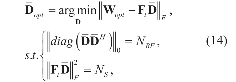
where the proposed of matrices Ftandare set auxiliary variables to obtain Aoptand Doptrespectively.Therefore,we can utilize the Ftanddiscussed in equation (13)and equation (14)to obtain corresponding Aoptand Dopt,respectively.
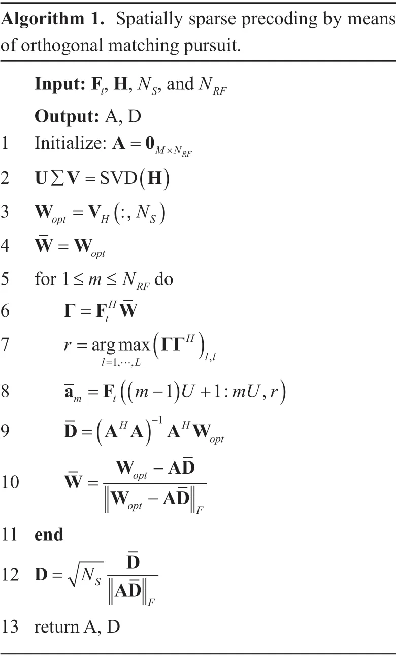
There are many algorithms to obtain the optimal precoder,such as OMP algorithm in [7],MO-AltMin algorithm in [22],CDM algorithmic in [23].However,this paper focuses on the performance of different antenna arrays of the BS.Considering the complexity of the algorithms,the OMP algorithm is chosen as the main idea to design the optimal precoder for four types of antenna arrays.The design of optimal hybrid precoder is presented as Algorithm 1.
Firstly,the hybrid precoding algorithm starts by the singular value decomposition of H to get the optimal hybrid precoding matrix Wopt.After that,the analog precoding matrix A can be got by finding the vector Ftalong which the optimal precoder has the maximum projection.The work in [7] has verified that the array response vector along which the optimal precoder has the maximum projection.Different from [7],the analog precoding A in this paper can be regarded as a diagonal matrix,and we hierarchically search for optimal sub-analog precoder matrixbased on the corresponding RF chain in step 8.When the analog precoder matrix is found,the least squares solution to D is calculated to remove the contribution to the selected vector in step 9 and step 10.Then,the column along which the residual precoding matrix W has the largest projection can be found at the next RF chain.It is worth noting that the transmit power constraint is exactly satisfied in step 12 and the Ftcan be set to different antenna arrays,such as ULA,URPA,UHPA,and UCPA.Based on the Algorithm 1,the corresponding analog precoder matrix A and digital procoder matrix D are obtained by four types of array response vectors.
Algorithm 1.Spatially sparse precoding by means of orthogonal matching pursuit.Input: Ft,H,NS,and NRF Output: A,D 1 Initialize: A 0=MN×RF 2 U V H∑ =SVD()3 W V= ,(:N)4 opt H S W W= opt 5 for 1≤ ≤m NRF do 6 Γ F W=tH 7 r=argmaxl L=1,,…(ΓΓH)ll,8))9 a Fm t= - + ((m U mU r 11: ,)-1=(H H D A A A Wopt 10 W AD opt -W=W AD opt -F 11 end 12 D D=NS AD F 13 return A,D
V.SIMULATION RESULTS
In this section,the antenna arrays beam pattern simulation results are performed and the SE and the received EE of hybrid precoding are compared with the proposed planar antenna arrays.Moreover,we analyse the tradeoff between SE and received EE for different precoding architectures.
Considering the fairness and convenienceof setting up antennas,the antenna array of receiver is same as BS,which employs ULA,UHPA,and UCPA withM=91,URPA withM=9×10,M=5×18,andM=2×45.URPA,UHPA,and URPA are set by the same geometric area which are equal to19.64λ,and the inter-element spacing is set to d=0.5λ,dx=dy=0.52λ,anddh=√3dx/2.Further,unless otherwise mentioned,an environment with 6 clusters and 8 scatters per cluster is considered and the angles of arrival (departure)are generated according to Laplacian distribution with random mean cluster angels (φr lÎ[0,2π))and angular spreads of 5 degrees within each cluster.
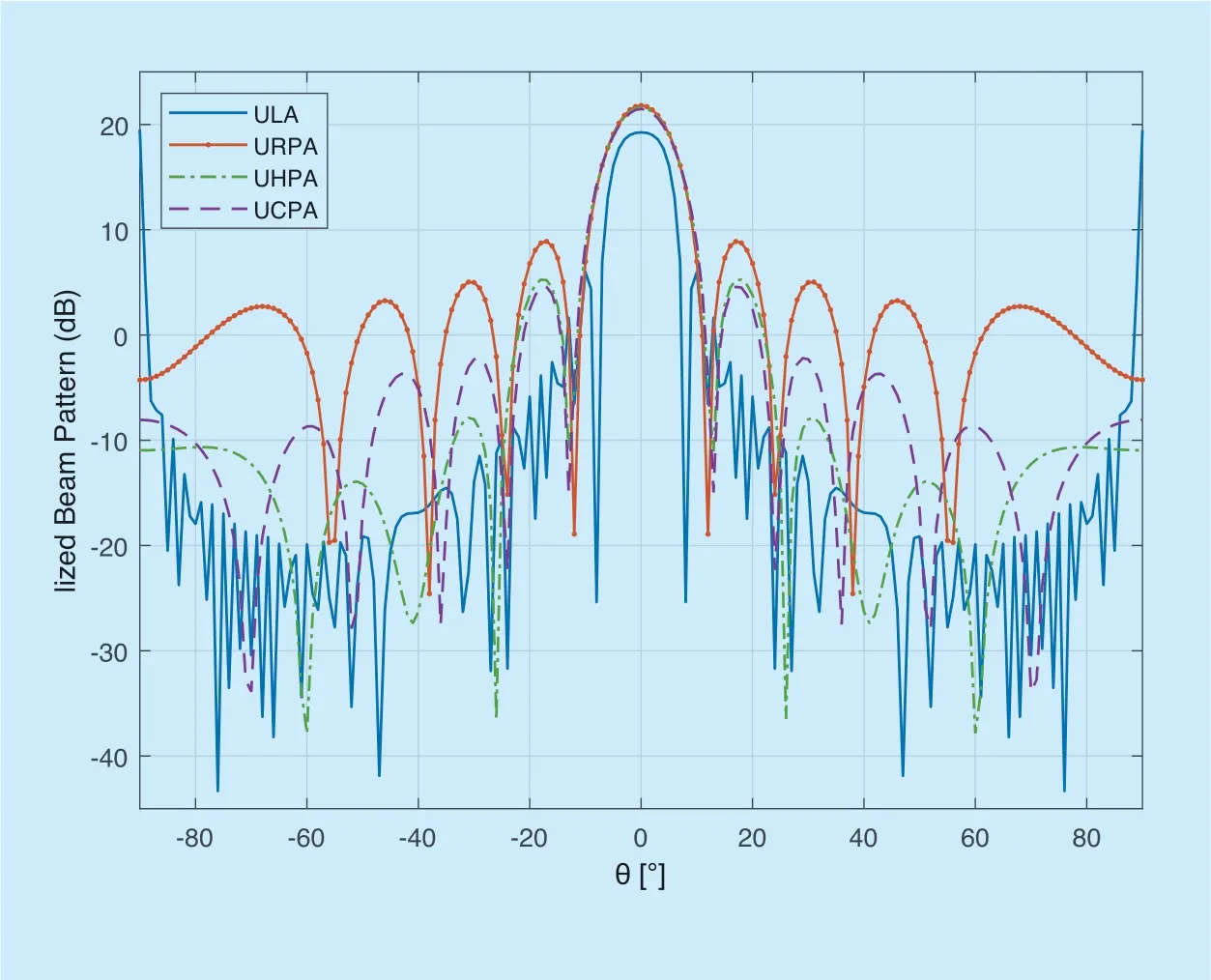
Fig.3.Normalized beam pattern for the proposed antenna arrays.
Figure 3 shows the normalized beam pattern of the proposed planner antenna arrays.Besides,the antenna array gain in theφ=π/2 plane for θÎ[-π/2,π/2].As the Table 1 show,the maximum gain of proposed antenna arrays is UHPA,which has level 21.67 dB from the maximum lobe,and the minimum gain is ULA,which has level 19.25 dB from the maximum lobe.The results that different antenna arrays of the maximum gain have effect on the analog precoder matrix A are introduced in Algorithm 1.Besides,compared to the ULA,URPA and UCPA configurations,the UHPA configuration has the lowest side lobe level of -8.25 dB.It indicates that adopting UHPA configuration yields severe interference compared to others proposed antenna arrays.
Figure 4 shows the SE comparison of ULA,UHPA,UCPA,and URPA withNS=1,K=16,andNRF=6.It can be observed from Figure 4 that the SE of URPA withM=9×10 is higher thanM=5×18,andM=2×45.When the URPA isM=9×10,the SE of the URPA,UHPA,UCPA are almost identical.The SE of ULA configurations is the lowest compared to other configurations.In the URPA,as the number of rows in the antenna array increases (a ULA can be seen as a single line of the URPA),the SE of the system increases.The reason is that antenna array is closely arranged result in the higher gain of the antenna array and the higher SE of the system.
In Figure 5,the SE variation with different numbers of RF chains is shown whenSNR=-5 dB.WhenNRF≤20 in linear array andNRF≤16 in planar arrays,the SE of the systems gradually increase as the RF chain increases.WhenNRF>20 in linear array andNRF>16 in planar arrays,the SE of the systems remain constant.These mean that the SE of system cannot be improved indefinitely as the number of RF chains gradually increases.This because the number of antennas of the BS and the transmitted data stream are limited,the system gain remains unchanged after a constant value.It is worth noting that under the sameNRF,the SE of ULA is lower than URPA,UHPA and UCPA.
Next,the received EE of the proposed antenna arrays hybrid precoding is evaluated.Based on the energy consumption model in [13],the received EEηEcan be defined as

wherePtis the transmitted energy,PRFis the energy consumed by RF chain,PPSis the energy consumed by phase shifters (PSs),andNPSis the number of required PSs.
Figure 6 shows the received EE comparison whenNRFvaries from 2 to 24,the practical valuesPt=1 W (about 30 dBm),PRF=250 mW,andPPS=1 mW in [14].From the Figure 6,it can be observed that the received EE of URPA,UHPA,and UCPA are identical when URPA withM=9×10 and the received EE of URPA withM=9×10 is higher than withM=5×18,andM=2×45.The received EE of URPA,UHPA,and UCPA are higher than ULA with the same ofNRF.Moreover,when the number ofNRFincreased,the received EE of proposed antenna arrays gradually reduce.Regardless of what kinds of the antenna array architectures,as we have already introduced the energy consumption of the system in equation (15),a single RF is 250% of a single PS consumption,so the RF chain is the main point of system energy consumption.
Next,we present the performance of the mmWave MIMO systems with different precoding architectures.Simulation parameters are set as follows.Typical mmWave massive MIMO congurations withM=91 andK=36 is considered.Antenna arrays at transmitter and receiver are both ULA with antenna spacingd=0.5λ.
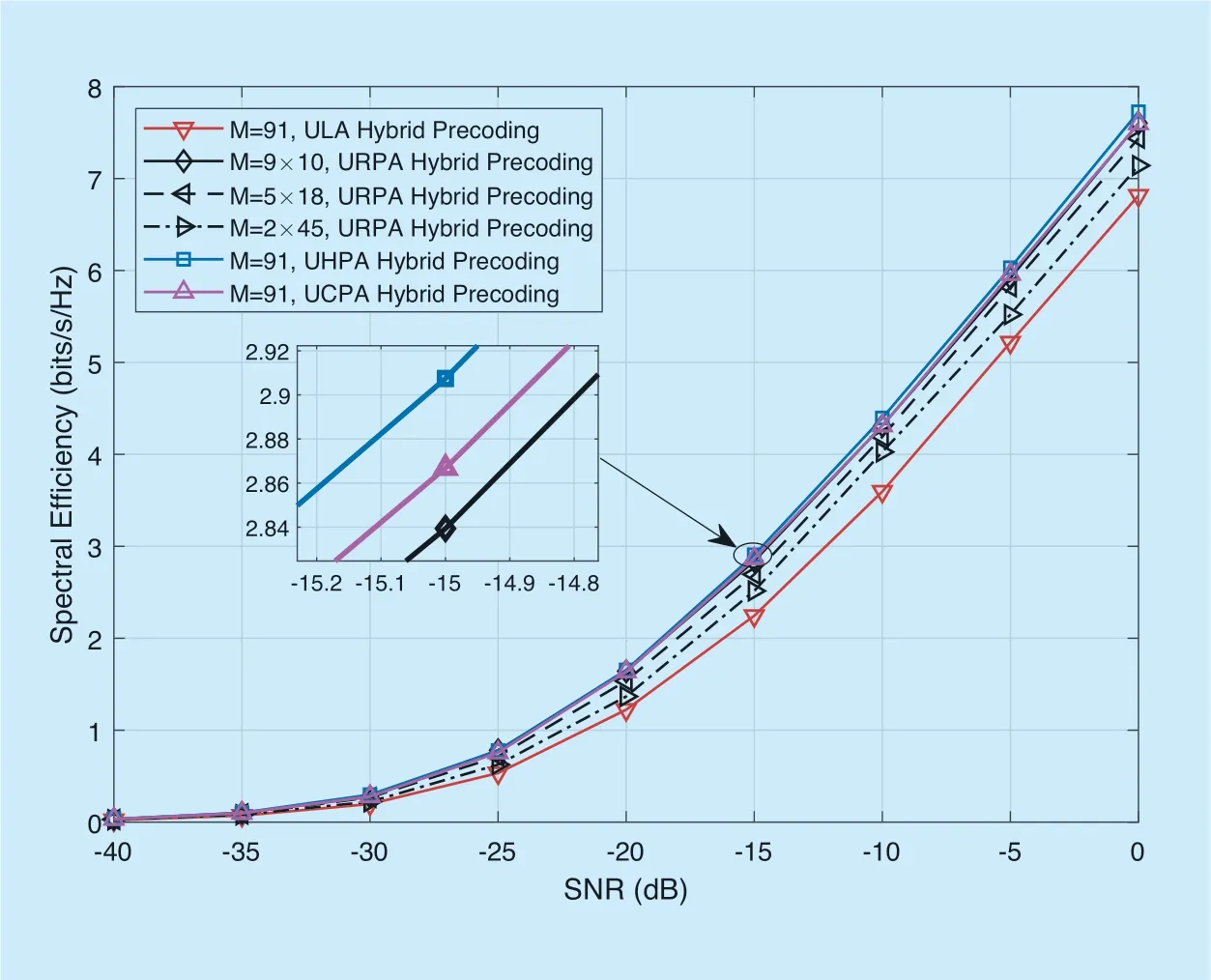
Fig.4.The SE of hybrid precoding with proposed antenna arrays.
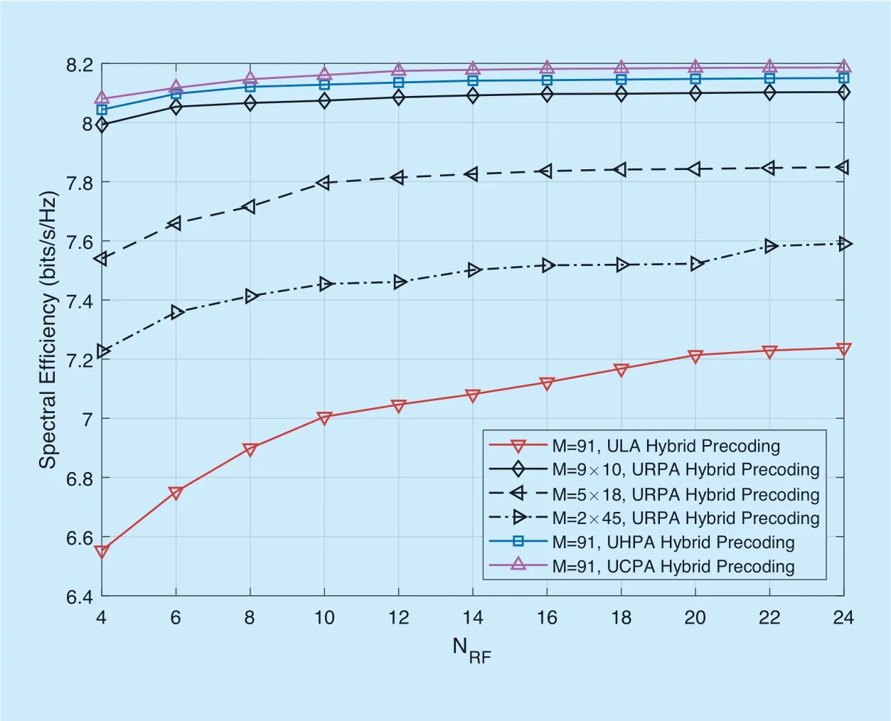
Fig.5.The SE comparison against the numbers of RF chains.
Considering the different precoding architectures,we research two aspects of performance including the SE and the received EE.Focusing on the SE of the system,we consider the perfect channel state information (CSI)scenario.Figure 7 shows the SE comparison in mmWave MIMO system with ULA,where the RF chains isNRF=4 and the number of antennas isM=91.We observe from Figure 7 that the SE of the three precoding architectures gradually increase with the SNR increasing,and the FCP and FDA outperforms the PCA with the same data stream.
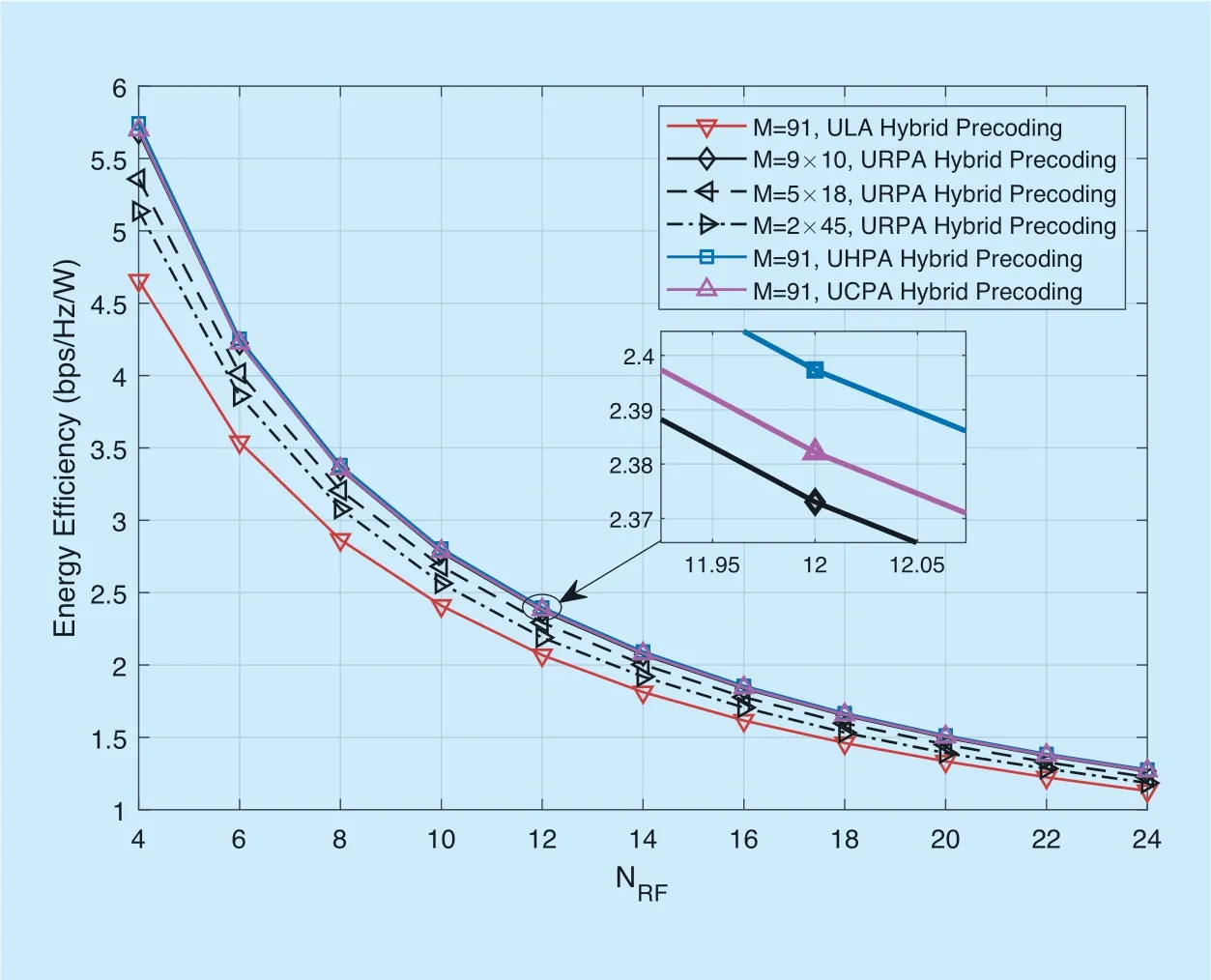
Fig.6.The received EE comparison against the numbers of RF chains.
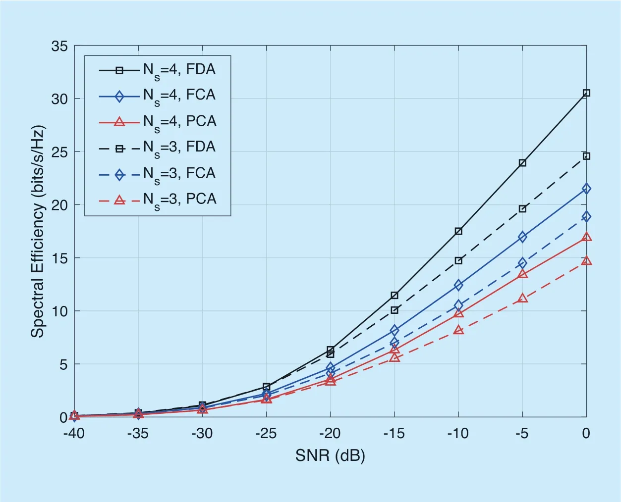
Fig.7.Spectral efficiency comparion for a mmWave massive MIMO system with ULA.
This is because of the characteristics of the FCA and FDA,that is,each RF chain of the FCA is connected to all phase shifters,and the FDA uses more RF chains without phase shifters to maximize system gain.
From the perspective of EE of the different precoding architectures,the PCA is compared with the FCA and the FDA.In Figure 8,the received EE of the different precoding architectures with respect the SNR is studied for a MIMO system with ULA,which the number of RF chains and antennas areNRF=4 andM=91,respectively.As we can see from the Figure 8,the received EE of the PCA is significantly outperforms the FCP and the FDA.In the case of low SNR,the received EE increases with the increasing of SNR,and the PCA increases greatly compared to the FCA and FDA.As the power consumption increases,since the gains on the SE are becoming smaller compared to the power costs,the received EE of all the precoding architectures decreases.Furthermore,for low SNR,it is observed that PCA is significantly more energy efficient than the FCA.When the received EE increases to a maximum,the performance of the PCA deteriorates significantly compared to the FCA and FDA.Using less PSs of the hybrid precoding for PCA,the received EE is lower than the other precoding architectures.
The trade-off of SE-EE is shown in Figure 9 for the different precoding architectures with different number of antennas.In the Figure 9,we can see that slight decrease in SEcan result in lager improvement in EE.The trade-off has similar behaviour for different precoding architectures,that is,as spectral efficiency increases,the energy efficiency of each precoding architectures decreases.In addition,increasing the data stream in the BS can significantly increase the energy efficiency and spectral efficiency of the system.It can be seen from the Figure 9 that the hybrid precoding with PCA has the lower spectral efficiency than other precoding architectures,but the received EE is highest.The reason for this result is because the PCA take the tradeoff between SE and received EE of the system where equipped the fewer PSs.
Next,we analyze the effect of CSI on the SE of hybrid precoding for massive MIMO systems.The estimated channel matrix (imperfect CSI)can be modeled as [25]

where H denotes the actual channel matrix,Θ∈ [0,1] presents the CSI accuracy,and E is the error matrix with entries following the distribution i.id.CN(0,1).
Figure 10 shows the SE comparison for aM=91 ULA mmWave MIMO system with the PCA,where the perfect CSI and the imperfect CSI with different Θ scenarios are considered.With the SNR increasing,the spectral efficiency of both perfect CSI and imperfect CSI will gradually increase.We observe that the PCA is not great sensitive to the CSI accuracy.For example,the SE of hybrid precoding when Θ=0.8 is close to that in the perfect CSI scenario,where the SNR gap is about 2 dB.Even when the CSI accuracy is pretty poor (i.e.,Θ=0.6),the hybrid precoding with imperfect CSI can still achieve more than 75% of the rate in the perfect CSI scenario.Additionally,Figure 11 shows the SE comparison for aM=91 ULA mmWave MIMO system with the FCA,where similar conclusions as those from Figure 10 can be derived.
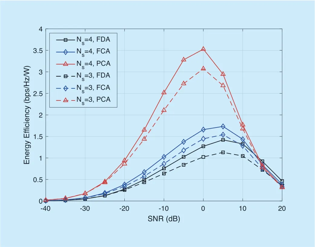
Fig.8.The received EE of the different architectures vs SNR for a mmWave massive MIMO system with ULA.
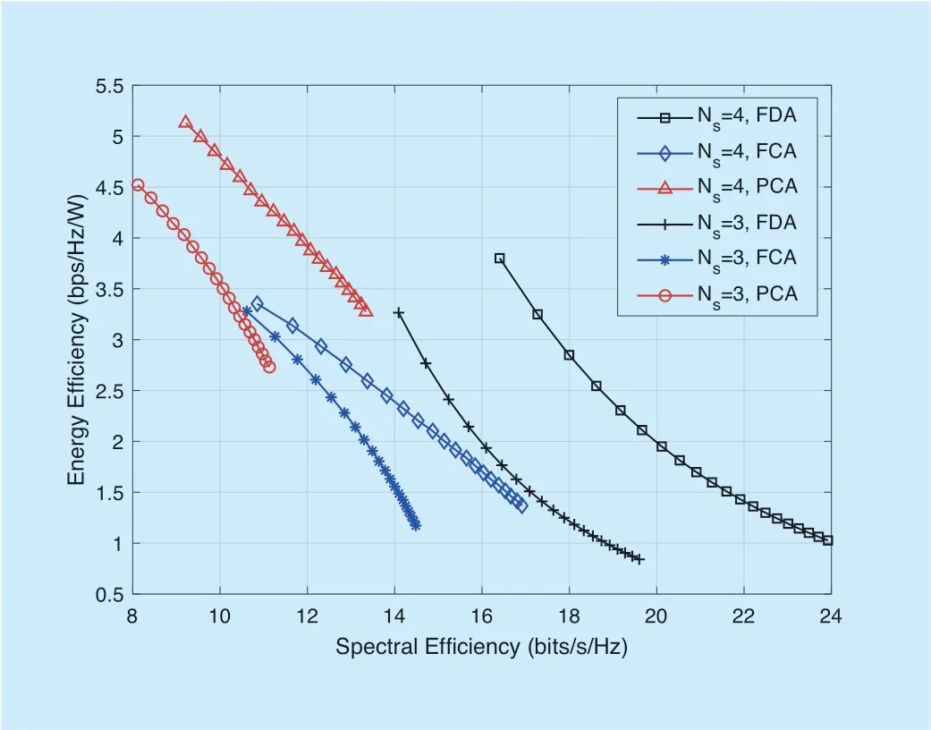
Fig.9.The trade-off between the received EE and SE of mmWave massive MIMO systems for ULA with different number of antennas.
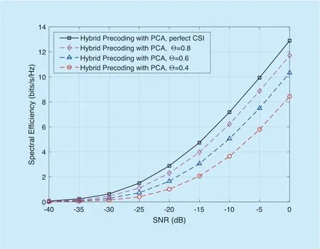
Fig.10.Impact of imperfect CSI on hybrid precoding for a mmWave MIMO system with PCA.
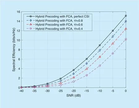
Fig.11.Impact of imperfect CSI on hybrid precoding for a mmWave MIMO system with FCA.
VI.CONCLUSION
The performance of the proposed antenna arrays and different precoding architectures were investigated.Besides,the simulated SE and received EE were provided.Fixed the number of receiver ULA,array gain of URPA,UCPA,and UHPA had almost identical performance and outperform ULA.This result in the SE of URPA,UCPA,and UHPA had almost identical performance.But the SE of ULA is outperformed.Whatever kinds of antenna arrays,when the number of RF chains is small,increasing it will lead to an improvement in the SE performance and there exists optimal radio-frequency chain numbers to maximize the SE.However,the performance of received EE is invariably decline by the number of RF chains increasing.Furthermore,the hybrid precoding of FCA and PCA have unique application advantages in energy efficiency and spectral efficiency,respectively.
ACKNOWLEDGEMENT
This work was supported by the National Natural Science Foundation of China (No.61961018),the Jiangxi Province Foundation for Distinguished Young Scholar (No.20192BCB23013),the Jiangxi Province Natural Science Foundation of China (No.20171BAB202001,20192ACB21003)and the Science Program of Jiangxi Educational Committee (No.GJJ180307).
- China Communications的其它文章
- Distributed Optimal Control for Traffic Networks with Fog Computing
- A Sensing Layer Network Resource Allocation Model Based on Trusted Groups
- New Identity Based Proxy Re-Encryption Scheme from Lattices
- A Real Plug-and-Play Fog: Implementation of Service Placement in Wireless Multimedia Networks
- TVIDS: Trusted Virtual IDS With SGX
- Application of Neural Network in Fault Location of Optical Transport Network

