A Novel Beam Design Method for mmWave Multi- Antenna Arrays with Mutual Coupling Reduction
Weizhi Zhong,Lei Xu,Qiuming Zhu*,Xiaomin ChenJianjiang Zhou
1 College of Astronautics,Nanjing University of Aeronautics and Astronautics,Nanjing 210016,China
2 College of Electronic and Information Engineering,Nanjing University of Aeronautics and Astronautics,Nanjing 210016,China
Abstract: To overcome the mutual coupling (MC)of multiple antennas in millimeter wave (mmWave)communication systems,a novel beam design method with low complexity is proposed in this paper.Firstly,an equivalent channel model incorporating the effect of MC is analyzed and established,and then an optimal precoding / combiner vector for beamforming is derived.On this basis,by using greedy geometric (GG)algorithm,a novel hybrid beam design method is proposed.Finally,the performance of proposed method is analyzed and compared with other traditional ones.The simulation results show that the proposed method has better suppression of the MC effect as well as lower complexity.
Keywords: millimeter wave (mmWave); antenna array; beam design; mutual coupling (MC); greedy geometric (GG)algorithm
I.INTRODUCTION
The increasing demand for high-speed reliable communication with improved user experience drives the development of the fifth generation (5G)wireless communication networks.It has been widely accepted that the capacity of the 5G wireless communication system should achieve 1000 times of that of the fourth generation (4G)long-term evolution advanced (LTE-A)wireless communication system.Also,the spectral efficiency of 5G systems is required to reach 3-5 times with respect to the current 4G LTE-A system [1].Millimeter wave (mmWave)communication has been considered as a key technology for the 5G communication scenarios,e.g.,wideband cellular communication (hotspot and small cell),wireless backhaul,indoor,and device-to-device (D2D)communications [2]-[4].
Compared to the traditional wireless signals with lower frequencies (below 30 GHz),the mmWave signal has severe path loss due to rain and oxygen absorption [5]-[6].Therefore,the antenna arrays of mmWave systems should be large enough,i.e.,massive MIMO systems [7]-[11],and thus to achieve sufficient directional gain.It is worth noting that if a large number of antennas are implemented in a small space,mutual coupling (MC)could not be negligible and it would affect antenna efficiency as well as deteriorate the system performance.
To solve this problem,by adding parasitic elements,authors in [12] introduced a double-coupling path to create a reverse coupling to reduce MC.In [13],one-dimensional electromagnetic band gap (1-D EBG)and split ring resonator (SRR)structures were inserted between two closely located monopole antennas to suppress MC.Note that,above two methods reduce the MC effect by optimizing antenna structures.In contrast,a beam design method based on an improved orthogonal matching pursuit (OMP)algorithm is proposed recently in [14] for supressing MC without changing antennas structures.However,the application of this algorithm is limited due to accuracy and efficiency.This paper aims to fill this research gap.Overall,the major contributions and novelties of this paper are summarized as follows:
1)An equivalent channel model incorporating MC effects for multiple antennas systems is analysed and established based on the investigation of MC mechanisms.
2)The optimal coding vectors for beam design are derived by using the equivalent channel model.
3)Based on the coding vectors,a novel beam design method involved GG algorithm is proposed to obtain the optimal beam pattern.
The rest of this paper is organized as follows.The system model with MC is established in Section II.A novel beam design method is proposed in Section III.The simulations and comparisons are performed in section IV.Finally,conclusions are given in section V.
We use following notations throughout this paper:Cdenotes the field of complex numbers,A is a matrix and a is a scalar.is the determinant of A,is Frobenius norm,wherea AT,A*,and A-1are transpose,conjugate transpose,and inverse,respectively.[A]R:,([A]:,R)are the rows (columns)of matrix A with indexes in the set R.E[·] is the expectation operator.
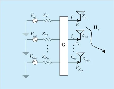
Fig.1.Equivalent system model with MC.
II.SYSTEM MODEL WITH MC
2.1 MC of multiple antennas
The small space between antenna elements makes induction current unneglectable,which can induce a new magnetic field and affect the signals of adjacent elements [15]-[16].
The equivalent MC model is shown in figure1,whereZ Ai(i=1 ,2,…,NBS)is the self-impedance,Vi(i=1 ,2,…,NBS)is the port voltage,ij(j=1 ,2,…,NBS)is the port current,ZSi(i=1 ,2,…,NBS)represents the power impedance,VSi(i=1 ,2,…,NBS)denotes the source voltage,G expresses the matrix of MC,and Hgis the equivalent channel model combining with the effect of MC.
For transmitter,the MC matrix can be derived as [16]

Furthermore,it's assumed that each antenna has the same characteristics,and the load impedances are equal,then we can simplify (1)to

Similarly,the MC matrix for the receiver can also be obtained as

whereZS,h,h ∈{t,r}is the load impedance,tandrrepresent the transmitter and the receiver,respectively.ZA,h,h ∈{t,r}is the self-impedance of antenna,Zs,h=diag{Z s,h,Zs,h,...,Zs,h} represents the load impedance matrix,ZtandZrare the mutual impedance matrix for transmitter and receiver,respectively,which are mainly related with antenna size and installation mode.
2.2 Equivalent channel model
A uniform linear arrays (ULA)system is considered.The transmitter employsNBSantennas controlled byNRFradio frequency (RF)chains,and the receiver is equipped withNMSantennas controlled byNRFRF chains.
The mmWave channel is usually dominated by a line-of-sight (LOS)path,while a few weak non-line-of-sight (NLOS)paths can be neglected [8].Therefore,the mmWave channel incorporating the MC can be modeled as

whereKmeans the Ricean factor,a0is the complex channel gain,N MS=MandN BS=Mare the antenna numbers of the receiver and transmitter,respectively,anddBS(θ)represents the antenna array response vector and for the case of ULA,it can be expressed as
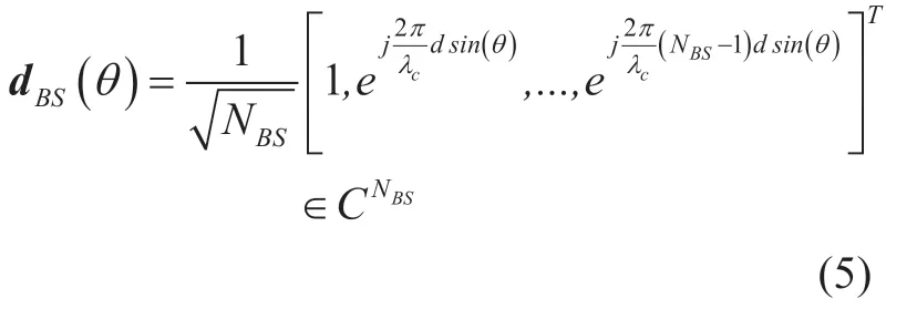
whereθ∈ [-π ,π] denotes the angle of departure (AOD),λcis the signal wavelength anddis the inter-element distance.Similarly,we can obtain the array responsedMS(φ)of the receiver,whereφ∈ [ -π,π] denotes the angle of arrival (AOA).
Base on the channel model of (4),the received signal after hybrid combining can be expressed as [17]-[19]

whereρmeans the signal-to-noise ratio,sis the transmitted symbol,ndenotes the Gaussian noise,andcis the beamformer at the transmitter,namely precoding vector [20] which is determined by the codebook and can be expressed as

III.HYBRID PRECODER/COMBINER DESIGN
3.1 Digital design
In order to overcome the problem of MC effect,we focus on the design of precoder / combiner.To simplify precoder / combiner design,we temporarily decouple the joint transmitter-receiver optimization problem.Firstly we design the precoding vectorcin a selfish way by using the available information Hgat the MS.Let us define the singular value decomposition (SVD)of channel as Hg= U ΣVH.Then,by defining the following two matrices Σ and V as

where Σ1∈ C1×1and V1∈ CM×1,the digital precoding vectorcoptcan be simplified as [21]

We take the achievable data rate as the system performance standard and it yields [22]

In order to optimize the hybrid precoders and combiners,it would be finding a solution that maximizes the achievable data rate in (10)by employing the available channel state information (CSI).If Hgandcopt= Σ1V1are known for the transmitter,the optimal combiner vectorwoptcan be obtained as [21]

Therefore,based on the value of Hg,coptandwopt,the date rateRcan be maximized.
3.2 Hybrid design
As proved in prior work,the optimal digital precoder / combiner can be achieved ascopt= Σ1V1andwopt=Hgcopt.However,in actual beamforming system,the RF terminals cannot directly generatecopt/wopt= Σ1V1,therefore,it is necessary to approximate the value with RF matrix and baseband vector [18].In the condition,a novel approach is proposed to design the hybrid precoders and combiners.
To simplify the system,we assume that the precoder and combiner have similar hybrid structures and here we only take the design ofcoptas an example to illustrate the improved method.
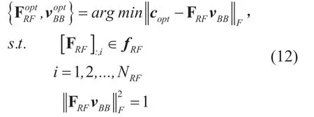
To design the beamformer for givencopt,the main approach in the literature is to use the Frobenius norm.That is,the analog beam steering matrix FRFand the baseband percodervBBare the solution of the minimization problem
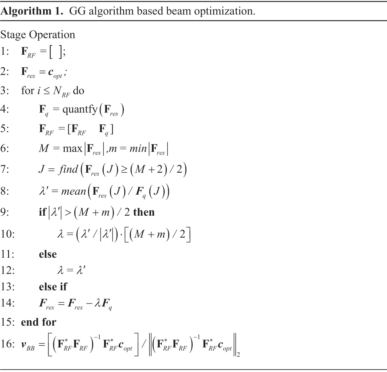
Algorithm 1.GG algorithm based beam optimization.Stage Operation 1: FRF = ;[ ]2: Fres opt =c ;3: for i N≤ RF do 4: F F=quantfy()5: F F Fq res=[ ]6: RF RF qM=max =F F,m min res res (Fres()(22))8: λ′=mean J / J 7: J find J M /=≥ +()F ())9: if (Fres qλ′ > +(M m /)2 then 10: (′ ′/ M m /λ λ λ= 2)11: else 12: λ λ= ′13: else if 14: F F F= -λ 15: end for 16: res res q/ ()2v)- -11=**(F F F F F Fc**cBB RF RF RF opt RF RF RF opt
wherefRF∈CNBSrepresents the analog beam forming vector consisting of elements {-1,+1,-j,+j}.Unfortunately,there is no closed-form solution for the minimization problem of (12).To access a feasible,but usually suboptimal solution,the optimization problem of (12)can be reformulated as a problem of sparse approximation solved by using OMP algorithm [14],which is proposed in most of the literature with advantage of simplicity.However,the inverse matrix of OMP algorithm will increase computational complexity.In addition,incomplete dictionary sets of OMP algorithm will reduce the computational accuracy.To overcome these problems,we employ a GG algorithm [23] to solve (12)in this paper.
The optimization process of FRFandvBBusing GG algorithm is shown in Table 1.Firstly,the residual matrix Fresis initialized bycoptand then is quantified with 2-bit RF phase shifters.Then,A OMP-based strategy is used to select the column vectors of beam control matrix FRFfrom the dictionary in stage 5.Compared to the OMP algorithm,we use the dictionary-free strategy and save only one matrix-vector multiplication to reduce computational complexity.Stages 6 to 13 refer to the residual update strategy.The process continues until allNRFbeam forming vectors have been selected.The algorithm normalizes the digital baseband combining vectorvBBto satisfy the constraintFinally,an optimal beam pattern in terms ofandcan be obtained.It should be noted that this algorithm approximatecoptby a hybrid analog-digital architecture with 2-bit RF phase shifters and does not require a dictionary set,which makes computational complexity lower than the OMP method.
IV.SIMULATION AND VALIDATION
In this section,we carry out numerical simulations to assess the performance of our proposed beam design method.First,the relationship between the MC effect and the simulation parameters is shown,and then,the proposed method is compared with the traditional ones in terms of data rate and complexity.
In the simulations,we assume that both of the transmitter and receiver suffer from the problem of MC.A 16-element ULA with the inter-element distance ofd=λ/2 is adopted at the transmitter and receiver.
4.1 Channel distortion
The channel distortion caused by MC effect is evaluated by the mean squared error (MSE)which can be calculated as

where H represents the mmWave channel matrix without considering MC effect,and it can be expressed as

The MSE listed in table 2 is used to compare the impact of MC on channel.At transmitter,the self-impedanc is set asZA,t= 73 +j42.5 Ω and the load impedance is given byZS,t= 73 -j42.5Ω .The load impedance matrixZtcan be obtained by the method in [16].At the receiver,we assume thatZA,r=ZA,t,andZS,ris set as 73 -j42.5Ω,60 -j30Ω and 73 +j42.5Ω,respectively.The carrier frequencyfcis set as 60GHz,10GHz,1GHz and 0.1GHz,respectively.In the simulation,the random AOA and AOD are uniformly distributed in a certain range of [-π/ 2,π/2].K≫1 and MSE is calculated with over 1000 Monte Carlo simulations.
As shown in Table 1,serious channel distortion caused by the MC effect is almost independent of the load impedanceZS,but closely related to the carrier frequencyfc.
4.2 Data rate
In this section,the performance of our proposed method is shown in terms of the data rate presented in (10).The self-impedance of antenna is set asZA,r=ZA,t= 73 +j42.5 Ω,and the load impedance is given byZS,r=ZS,t= 73 -j42.5Ω .The carrier frequency isfc=60GHz,and AOA / AOD is uniformly distributed in a certain range of [-π/ 2,π/2].The value of precoding / com-biner vectorcopt/woptis chosen according to (9)and (11).
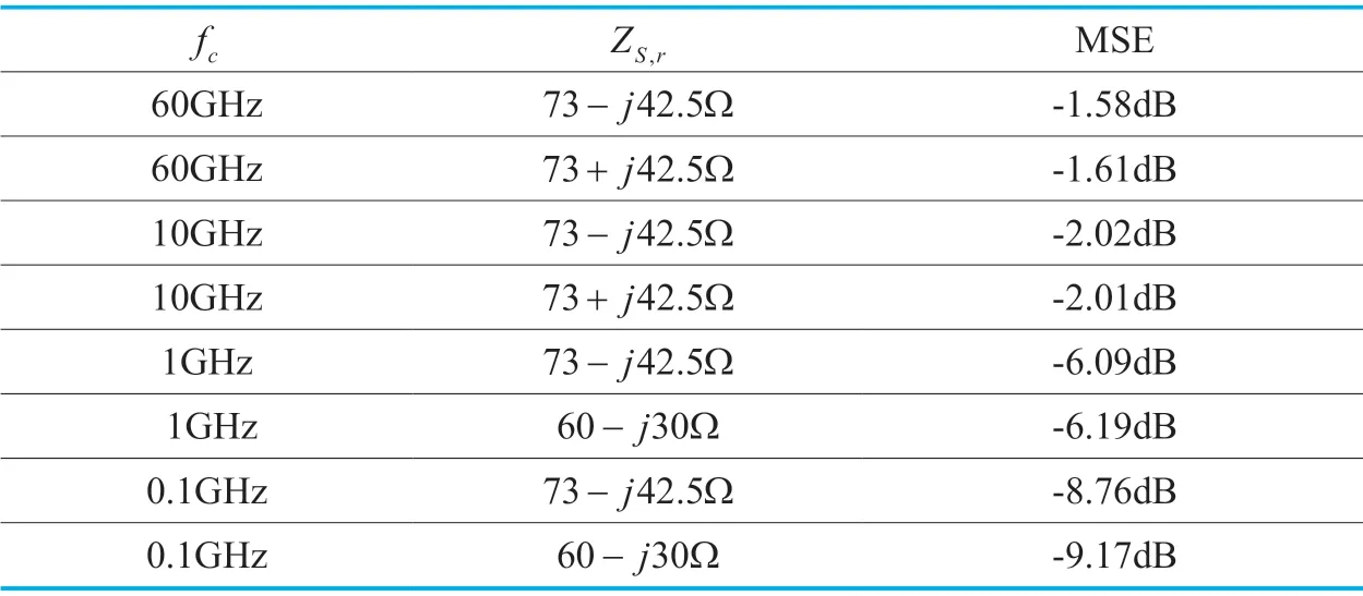
Table I.MSE caused by MC effect.
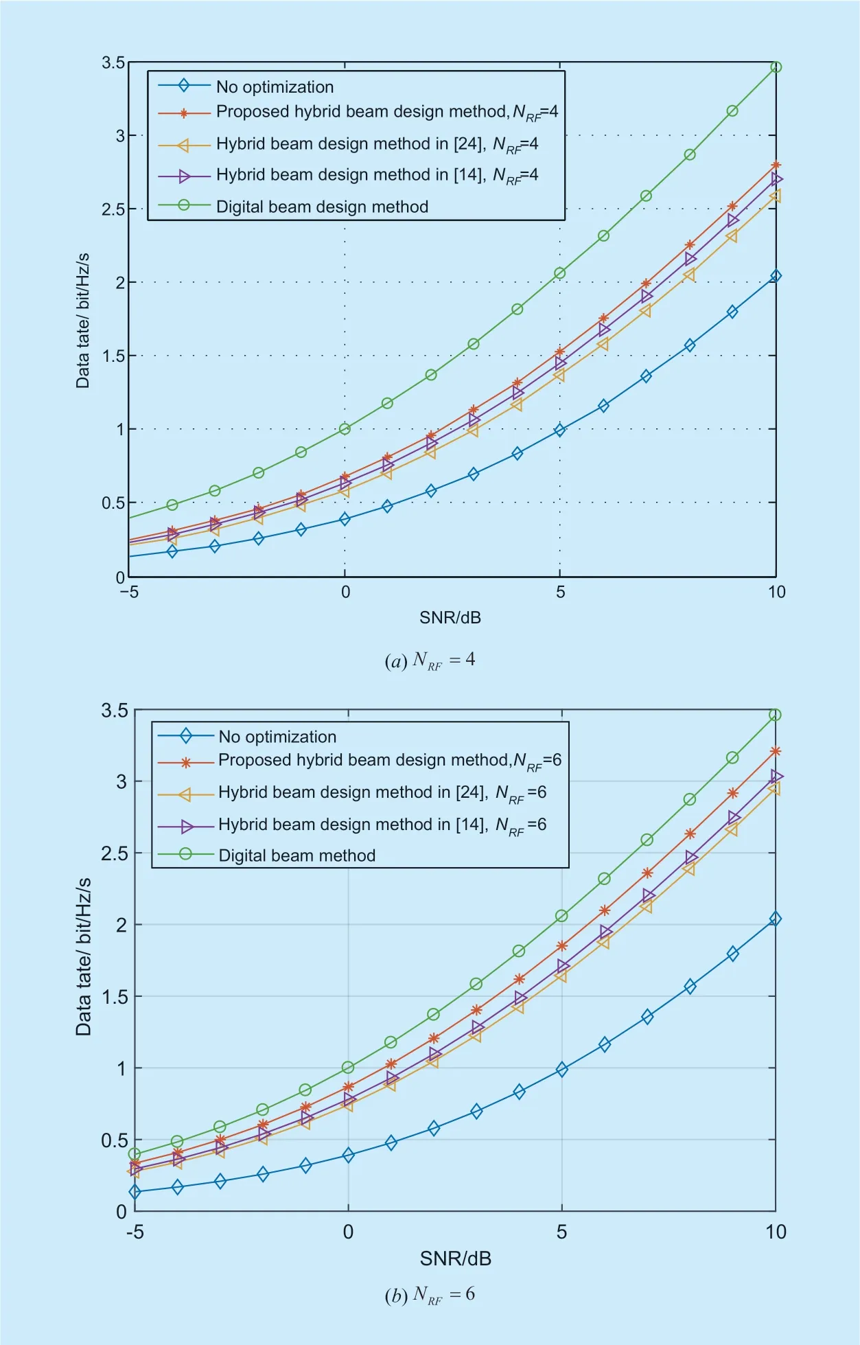
Fig.2.Data rate performance of different methods.
The data rate is evaluated by Monte Carlo simulations with 5000 independent channel realizations and the comparisons are shown in figure2 withNRF=4 orNRF=6.
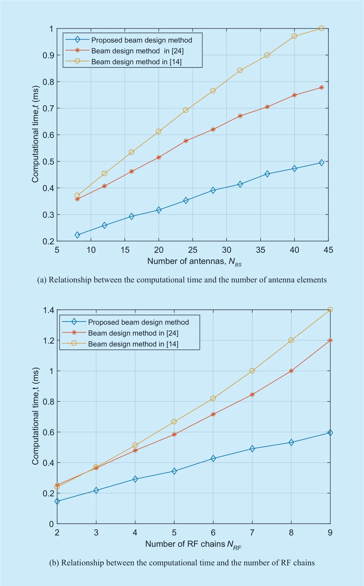
Fig.3.Comparison of complexity.
It can be observed that the MC significantly degrades the data rate if no optimization techniques are performed.The reason is that the beam shapes and directions are seriously impacted by the MC effect.In the case,the data rate performance would become worse as the gain of main lobe decrease while the interference of side lobes increase.Moreover,the comparisons between our proposed beam design method and other schemes presented in [14] and [24] are shown in figure2.From figure 2(a)and figure 2(b),it can be seen that our proposed hybrid beam design method outperforms others.The reason is that the OMP-based approaches rely on non-complete dictionaries made of basis subsets.In contrast,our proposed method is a dictionary-free approach based on geometric considerations and manipulations.In the case,the impact of the non-complete dictionaries is reduced.
A comparative analysis on the computational complexity of our method versus the conventional algorithms is carried out in figure3.In the simulation,a computer of Pentium dual-core Intel core i5 is adopted and all numerical results are obtained from Monte Carlo simulations with 5000 independent channel realizations.As shown in figure3 (a),for the same number of RF chains,e.g.NRF=6,the proposed method consumes shorter computational time than others.The efficiency of different methods by the number of antenna elements is also compared in figure 3 (b),which shows the computational time of proposed method is much less than others for the same number of antenna elements,e.g.,NBS=16.The reason is that despite their simplicity and ease of implementation,OMP-based approaches share the disadvantage of high computational complexity (due to a matrix inversion at each step).In contrast,our proposed method has the nature of dictionary-free and geometric intuitions which avoid giving too much manipulations of matrix inversion.
V.CONCLUSION
A novel beam design method to suppress the effect of MC for multiple antennas in mmWave communication systems has been proposed in this paper.A hybrid beamforming architecture has been adopted and the MC effect has been considered.By using a GG algorithm,the beam pattern with reducing MC has been optimized.The simulation results have validated that our proposed method has the better performance in data rate i.e.,MC suppression,and complexity reduction.Note that the proposed algorithm is only suitable for time-invariant channels.In the future work,we will extend the proposed beam design method to the time-variant channels.
ACKNOWLEDGEMENTS
This work was supported by Aeronautical Science Foundation of China (2017ZC52021),the Major Program of National Natural Science Foundation of China (61827801).
- China Communications的其它文章
- Distributed Optimal Control for Traffic Networks with Fog Computing
- A Sensing Layer Network Resource Allocation Model Based on Trusted Groups
- New Identity Based Proxy Re-Encryption Scheme from Lattices
- A Real Plug-and-Play Fog: Implementation of Service Placement in Wireless Multimedia Networks
- TVIDS: Trusted Virtual IDS With SGX
- Application of Neural Network in Fault Location of Optical Transport Network

