The Characteristics Analysis and Cogging Torque Optimization of a Surface-Interior Permanent Magnet Synchronous Motor
*
(1. College of Electric Engineering, Zhengzhou University, Zhengzhou 450000, China;2. School of Electrical Engineering and Automation, Henan Polytechnic University, Jiaozuo 454003, China;3. School of Automation, Nanjing University of Aeronautics and Astronautics, Nanjing 211106, China;4. School of Engineering and Applied Science Aston University, Birmingham B47ET, UK)
Abstract: This paper proposes optimal stator skewed slot analytical method for cogging torque reduction in surface-interior permanent magnet synchronous motor(SIPMSM) and analyzes the characteristics of SIPMSM. The series-parallel equivalent magnetic circuit models(EMCMs) of SIPMSM is built based on the characteristics of magnetic circuits, which is used to design the basic electromagnetic parameters of SIPMSM. Analytical expressions of cogging torque are derived from applying analytical techniques. Stator skewed slot for cogging torque minimum is adopted, and the stator skewed slot pitch is confirmed based on the analytical expressions of the resultant cogging torque.The cogging torque, torque ripple, back electromotive force(back-EMF), power-angle characteristics,efficiency and power factor of SIPMSM are analyzed by establishing 3-dimensional finite element model(3-D-FED) of SIPMSM with stator skewed slot and straight slot. It is shown that the comprehensive performance of optimized SIPMSM is improved as confirmed by finite element analysis and analytical calculation results.
Keywords: Surface-interior permanent magnet synchronous motor(SIPMSM), cogging torque,stator skewed slot, three-dimensional finite element model(3-D-FED).
1 Introduction
Due to simple structure, constant speed, high torque density and efficiency, the permanent magnet synchronous motor(PMSM) has a wide range of industrial applications. However, the interaction between rotor permanent magnets and stator slots can produce cogging torque, which will have effect on control precision, especially in low speed.
PMSM with permanent magnets skewing for cogging torque and torque ripple minimum was investigated[1-5], where the cogging torque can be eliminated by skewing permanent magnets by a particular angle. Various methods have been used to suppress the cogging torque from the view of motor design, such as the choice of slot and pole number combination, optimization of magnet pole arc,asymmetrical distribution of magnet pole, optimization of slot opening width, notching auxiliary slot, and skewing slots or magnets[6-12]. However, in order to ensure the serial magnetic circuits of surface-interior permanent magnet synchronous motor(SIPMSM) with surface permanent magnet(SPM) and interior permanent magnet(IPM), the manufacturing process becomes more complicated. Therefore, skewing permanent magnet is not well suited to reduce cogging torque of SIPMSM. In[6-10], a skewing factor related to the skewing angle is introduced to analyze the effects of skewing on cogging torque. Although they conclude that skewing the stator slots and skewing the rotor magnets has the same effect and skewing one cogging torque period can eliminate the cogging torque, this method does not provide practical field distribution for a skewed machine. Slot skewing that can improve the back electromotive force(back-EMF) and suppress mutual torque ripple with insignificant motor structure change has been widely used in the electrical machine production[13-14]. For slot skewing, air-gap flux distribution varies along the entire length of the machine in the axial direction, which introduces a number of problems in the field calculation and performance analysis of machines with skewed slots[15]. Cogging torque minimum of PMSM with different slot widths and positions was studied[16-18]. The PMSM having more options of optimal slot opening sizes and positions for minimizing cogging torque are more sensitive to manufacturing tolerance of slot sizes and positions, however, this method is generally impractical since the manufacturing of stator slots becomes more complicated. The rotor teeth pairings were proposed for reducing cogging torque[19], although the method is only appropriate for flux-reversal machines. In [20-22], the 3-D finite element(FE)numerical technique is used for the field solution for the entire machine with skewing. Although this technique can provide accurate results, it requires a large amount of computational resources for practical design applications, and is therefore time-consuming and inefficient. In [23-25], minimizing cogging torque with auxiliary slots was researched, but the method can not reduce the cogging torque of SIPMSM with 24 slots and 4 poles. In [26-27], the pole arc coefficient combination optimization algorithm is adopted to reduce cogging torque, however, change of the pole arc coefficient will influence performance of SIPMSM. An analytical technique where cogging torque was associated with the synthesis of a single stator slot was presented[28], and the theory can be used to analyze the resulting cogging torque of SIPMSM.
Aiming at the proposed structure in the paper, the series-parallel equivalent magnetic circuit models(EMCMs) of SIPMSM is established based on the characteristics of magnetic circuits. EMCM is used to design the basic electromagnetic parameters of SIPMSM.The stator skewed slot is adopted to optimize SIPMSM for minimum cogging torque. Finally, the 3-dimensional finite element model(3-D-FEM) is established to calculate and analyze the effects of stator skewed slot on the performance of SIPMSM.
2 Determination of parameters
The rotor of SIPMSM contains SPM, IPM, rotor core and shaft. The main magnetic field is created jointly by SPM and IPM which form serial magnetic circuits. The topology structure reduces the magnetic flux leakage as well as enhances air gap flux density and the mechanical strength of motor. The structure of SIPMSM is shown in Fig.1.
The basic electromagnetic design scheme of permanent magnet motor is analyzed by EMCM. Aiming at the spatial topological structure of the PMs in SIPMSM, the serial-parallel EMCM is established based on the redistribution of SPMs. There are two parallel branches in the model, the magnetic flux paths of SIPMSM are shown in Fig.2. The No.1 path is the serial magnetic circuit composed of most the SPMs and the IPMs. The No.2 path is the serial magnetic circuit composed of the rest parts of the SPMs.
The EMCM is shown in Fig.3 while the simplified EMCM in which the saturated effect and the influence of magnetic flux leakage are ignored is shown in Fig.4.

Fig.1 The structure of SIPMSM

Fig.2 The magnetic flux paths of PMs

Fig.3 The series-parallel EMCM
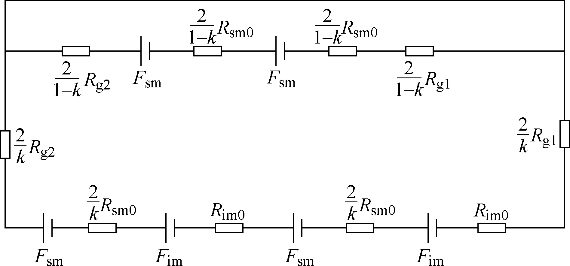
Fig.4 The simplified series-parallel EMCM
In the model, the SPMs and IPMs are equivalent to the serial structure of the magnetic motive fore and the magnetic resistance, the magnetic motive fore of the SPMs and IPMs are calculated respectively in (1) and (2).

WhereHcdenotes coercive force of PMs,hsmis the length of magnetization direction of SPMs,himindicates the length of magnetization direction of IPMs. The magnetic resistances of one SPM and one IPM are calculated respectively in (3) and (4).

Whereμ0represents the permeability of air,μ0is the relative permeability of PMs.Ssmis the equivalent area of one SPM,Simdenotes the area of one IPM, which are calculated respectively in (5) and (6).

WhereDsmis the equivalent diameter of one SPM,lsmrepresents the axial length of one SPM,θis the range of mechanical angle covered by one SPM,wimindicates the width of one IPM,limis the axial length of one IPM.The air-gap magnetic resistancesRg1andRg2are calculated in (7).hgis the thickness of the air-gap.Sgdenotes the equivalent area of the air-gap above one SPM and calculated in (8). Wherelgis the axial length of air-gap.


WhereRsm0is the magnetic resistance of one SPM,Rim0is the magnetic resistance of one IPM,Rr1is the magnetic resistance of rotor core in No.1 path,Rr2is the magnetic resistance of rotor core in No.2 path,Rsr1,Rsr2are the leakage magnetic resistances between the SPMs in No.1 path and the rotor core,Rsr3,Rsr4are the leakage magnetic resistances between the SPMs in No.2 path and the rotor core,Rir1,Rir2are the leakage magnetic resistances between the IPMs and the rotor core,Rt5,Rt6,Rt7,Rt8,Rt9,Rt10are the magnetic resistances of the stator teeth,Rts5,Rts6,Rts7,Rts8,Rts9,Rts10are the magnetic resistances of the stator teeth boots.
Thekrepresents the proportional coefficient taken by SPMs in No.1 path, which is calculated in (9).θ1is the range of mechanical angle covered by one SPM part which is over against the interior “V” shape PMs in one pole.

The main magnetic flux of No.1 pathΦδ1and the main magnetic flux of No.2 pathΦδ2are calculated respectively in (10) and (11).
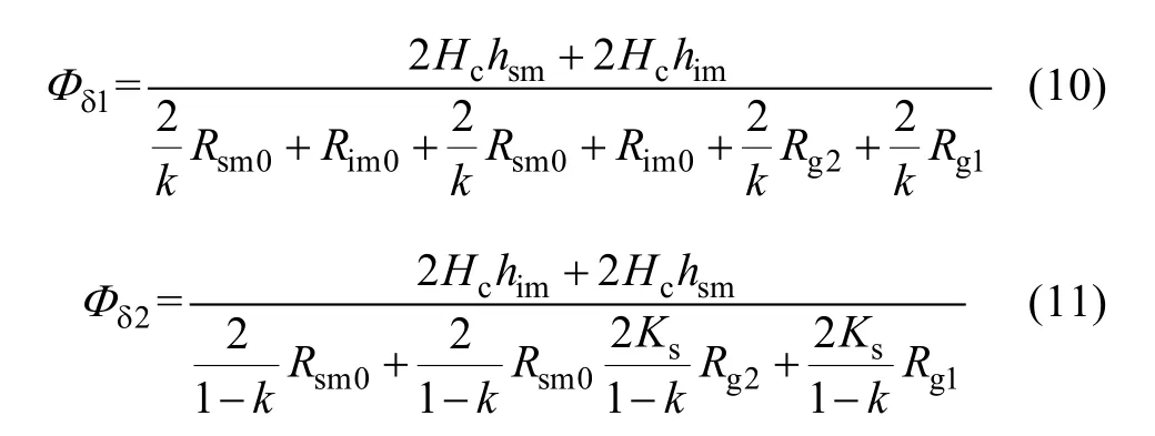
The air-gap magnetic flux density is calculated in(12). The back-EMF fundamental harmonic RMS is calculated in (13).

Wherefrepresents the frequency of stator armature back-EMF,Nis the turns of single phase windings,Kw1is the fundamental harmonic windings factor of single phase windings. To calculate theKw1conveniently,the single chain windings is turned into whole pitch distribution windings. The final electromagnetic parameters of SIPMSM are shown in Table 1. The cogging torque is shown in Fig.5.
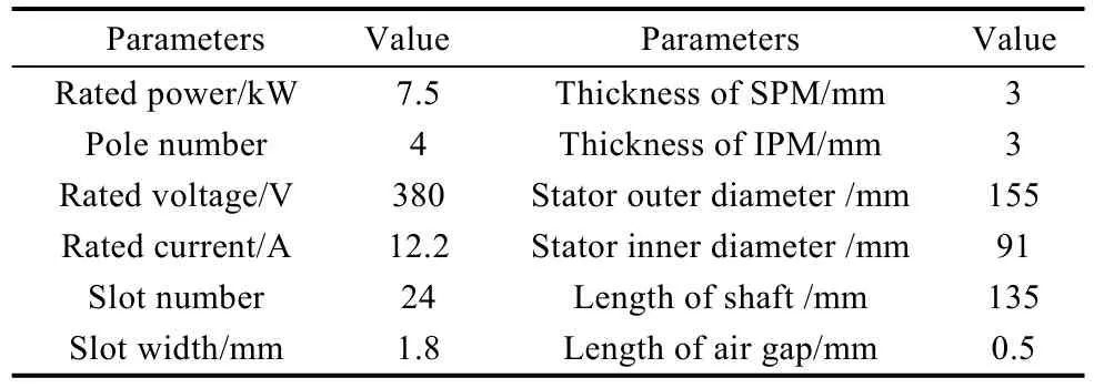
Table 1 The parameter of SIPMSM

Fig.5 Cogging torque
Fig.5 shows that the peak of cogging torque is 4.31Nm. The cogging torque affects many performance indicators of SIPMSM, which need to be optimized.
3 Analytical model of cogging torque
The cogging torque of SIPMSM can be expressed as:
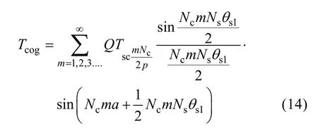
Wheremis integer,Ncis the least common multiple between slot number of statorQand the number of pole 2p, the cogging torque can be zero when meeting (15).

Thus the cogging torque can, in theory, be eliminated whenNsmeet (16).

Wherekis positive integer, with regard to SIPMSMQ=24, 2p=4, soθ= 24, the (16) can be transformed into (17).

4 Simulation and analysis
Segment algorithm is often used to study the influence of stator skewed slot on performance of the motor. The magnetic field of every segment is calculated by two-dimension finite element modeling, and the performance of the motor is analyzed by evaluating the results of every segment. Although this method can reduce the simulation time, the analysis process of the results is complicated and the results are inaccurate. To obtain more accurate results, the 3-D-FED of SIPMSM with stator skewed slot and stator straight slot are established. The 3-D-FEDs are shown as:
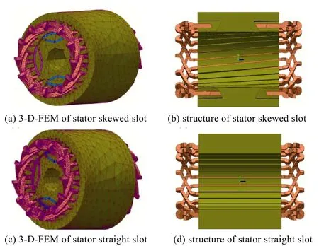
Fig.6 The 3-D-FEM of SIPMSM

Fig.7 Cogging torque and harmonic spectrum of SIPMSM with stator skewed slot and straight slot
Fig.7 shows that there is good agreement between the resultant cogging torque obtained from finite element analysis and predicted results deduced from analytical expressions together with harmonics spectrum mainly consisting of six times harmonics. The amplitude of the resultant cogging torque is reduced by about 93.4% when stator slots are skewed by one-slot pitch.Although mutual counteracting of cogging torque produced by a simple slot can eliminate the resultant cogging torque, simulation results show that the resultant cogging torque cannot be thoroughly eliminated. Due to the torque produced by interaction between permanent magnets and end region of rotor core, the precision of air gap grid subdivision can also cause the phenomenon in process of simulation analysis.
Fig.8(a) shows that the electromagnetic torque of SIPMSM with stator skewed slot is reduced about 0.8%,and the influence of the stator skewed slot is slightly less than one of stator straight slot. The motor reaches synchronous operation state after about five periods. The torque ripple is reduced from 13.02% to 4.54%, which is greatly improved with stator skewed slot, due to smallwe cogging torque.
Fig.9 shows that characteristics of torque vs. power angle of SIPMSM with stator skewed slot and straight slot are similar. Conclusions that the stator skewed slot has minimal effect on the point of maximum torque and overload capability can be drawn. The electromagnetic torque reaches to peak when power angle is about 110 degree, and the overload multiple is about 2.8, showing that the proposed SIPMSM possesses good overload capability.

Fig.8 The electromagnetic torque of SIPMSM at rated state
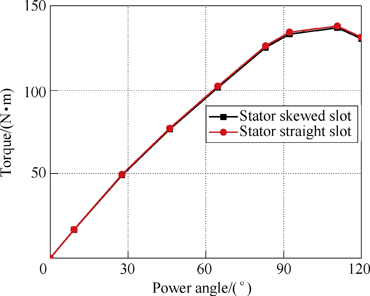
Fig.9 The relationship between torque and power angle
5 Experimental verification
The prototype is manufactured and the test system is also set up, which is shown as Fig.10.
The waveforms of measured speed and command speed of SIPMSM with stator straight slot operating at no-load are shown in Fig.11. Real-time data of speed can be determined by monitoring of the controller.

Fig.10 Prototype of SIPMSM
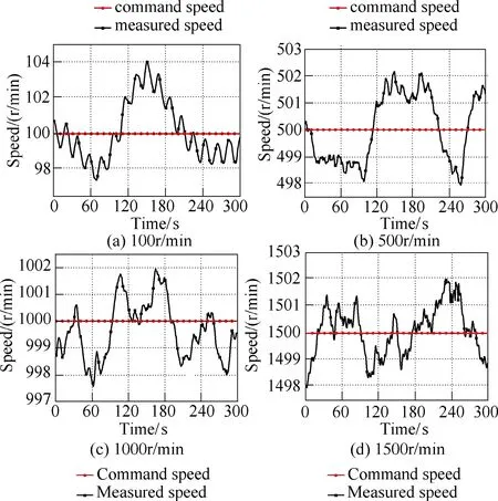
Fig.11 The waveforms of measured and command speed for prototype at no-load
Fig.11 shows that the waveforms of measured speed and command speed operating at 100r/min、500r/min、1000r/min、1500r/min. There are deviations of about 1.7%、0.45%、0.21%、0.2%, appearing in an inversely proportional relationship between deviations and operational speed. To improve the control precision,an effective method is adopted to optimize the SIPMSM for minimizing the cogging torque and torque ripple which can lead to vibration and deviations in drive systems.
Based on the optimal model of SIPMSM, the waveforms of back-EMF are shown in Fig.12, which shows that the amplitude of their back-EMF are approximately equal, but back-EMF of SIPMSM with stator skewed slot have better sinusoidal characteristics compared with SIPMSM with stator straight slot. The harmonics are reduced about 47.14% by adopting stator skewed slot, but cannot be thoroughly eliminated because the wave length of some harmonics is longer than skewed slot pitch.
In Fig.13, the efficiency of SIPMSM with stator skewed slot and straight slot is approximately equal,SIPMSM with stator skewed slot has longer windings,which will increase copper losses, whereas stray losses decrease due to reduction of harmonics of air gap magnetic field. The efficiency of the prototype is less than that of the simulation results because of influences of the external environment. The power factor of SIPMSM is shown in formula (18):


Fig.12 The waveforms of back-EMF for SIPMSM

Fig.13 The relationship between the output power and the efficiency and power factor of SIPMSM
WhereE0is back-EMF,UNis rated voltage,I1is current of stator windings,Idis current of direct-axis,Iqis current ofq-axis,X1is stator leakage reactance,Xad,Xaqis armature reaction reactance ofd-axis andq-axis.The (18) shows that the stator skewed slot has no effect on power factor, and the analytical results correlate well with the results of simulation and prototype test.
6 Conclusions
The analytical expressions of cogging torque are derived and the stator skewed slot pitch is confirmed to eliminate cogging torque and reduce torque ripple. The characteristics of SIPMSM are analyzed by finite element method and prototype tested in the paper. Some conclusions can be obtained by comparing with calculation and simulation results.
(1) The method optimizing SIPMSM with stator skewed slot can reduce cogging torque and torque ripple,improving the sinusoid of back-EMF and control precision. However, the cogging torque cannot be thoroughly eliminated in the finite element model of the stator skewed slot, due to the effect of the other harmonics.
(2) The harmonics of back-EMF of SIPMSM with stator skewed slot is reduced. The proposed SIPMSM possesses good overload capability, high efficiency and power factor.
 Chinese Journal of Electrical Engineering2018年4期
- Chinese Journal of Electrical Engineering的其它文章
- Battery Charging Method for Electric Vehicles:From Wired to On-Road Wireless Charging
- Using Inverter-Based Renewable Generators to Improve the Grid Power Quality—A Review
- Review of Power Decoupling Methods for Micro-Inverters Used in PV Systems
- Resonance Active Damping and PCC Voltage Quality Improvement of DFIG System Connected to Parallel Compensated Grid
- Field-Oriented Control and Direct Torque Control for a Five-Phase Fault-Tolerant Flux-Switching Permanent-Magnet Motor
- Study of Pressure Balance for Press-Pack IGBTs and Its Influence on Temperature Distribution
