Field-Oriented Control and Direct Torque Control for a Five-Phase Fault-Tolerant Flux-Switching Permanent-Magnet Motor
Binyu Wu, Dezhi Xu*, Jinghua Ji, Wenxiang Zhao, and Qingwang Jiang
(1. School of Electrical and Information Engineering, Jiangsu University, Zhenjiang 212013, China;2. Jiangsu Key Laboratory of Drive and Intelligent Control for Electric Vehicle, Zhenjiang 212013, China)
Abstract: This paper presents a comparative performance analysis of a new five-phase fault-tolerant flux-switching permanent-magnet(FT-FSPM) motor for high-reliability applications under the two most popular control schemes, namely, field-oriented control(FOC) and direct torque control(DTC) based on stator-flux orientation. Firstly, the new motor topology and structural characteristics are briefly presented. Secondly, the d- and q- axis for the FT-FSPM motor are defined,which is crucial to the mathematical model and control scheme, and the mathematical models are derived. Then, two control schemes, i.e., FOC and DTC, and the main system are proposed. The operational principles of the two control schemes are presented, and space vector pulse width modulation(SVPWM) based on four neighboring vectors is adopted to reduce current harmonics and torque ripples. Finally, the simulated and experimental results are given, and performance analysis of the two control schemes are compared and discussed. The results reveal that FOC scheme has the sinusoidal phase current and low torque ripples, while the DTC scheme has fast dynamic response,verifying the effectiveness of the two proposed control schemes. This paper is a primary investigation for more possible improvements in the control schemes of the five-phase FS-FTPM motor.
Keywords: Flux-switching, five-phase motor, permanent-magnet motor, filed-oriented control,direct torque control.
1 Introduction
Traditional rotor-permanent magnet(PM) motors have cooling problems, which leads to irreversible PM demagnetization, limiting the electrical output capacity,reducing power density and so on[1-2]. To overcome this problem, electrical motors equipped with PMs in the stator have been proposed, having good thermal dissipation and mechanical integrity for high-speed applications[3]. Among the existing stator-PM motors,flux-switching PM(FSPM) motors have the highest power density due to their high air-gap flux density caused by flux-focusing effect[4-9].
On the other hand, the conventional three-phase motors may not fully meet the demands of some applications which require high power rating and reliability. However, multi-phase motor drives have many advantages over three-phase configurations, e.g.,reducing the amplitude and increasing the frequency of torque pulsations, reducing the rotor harmonic current losses and lowering the DC link current harmonic[1,10-11].Also, fault tolerance of motors is extremely important for many high-reliability applications such as aerospace and vehicle drive systems[12-16]. In recent years, some faulttolerant motors have been developed. By incorporating the modular structure, alternate poles and redundant windings into the existing motor design, fault- tolerant capability can be achieved[17-19]. In particular, by employing a multi-teeth topology in the stator, a new five-phase fault-tolerant FSPM(FT-FSPM) motor has been proposed[20-21].
However, most of the available publications on the FT-FSPM motors are focused on performance analysis and design, rather than their control strategies and operational performance. Therefore, it is necessary to develop theoretical and experimental research on control of FT-FSPM motor drives.
Both field-oriented control(FOC) and direct torque control(DTC) are two of the most popular methods for high performance AC motor drives[22]. FOC is the first proposed high performance control scheme. It can be derived based on thed-qmodel of AC motors, converting them into equivalent separately excited dc motors, which have highly desirable control characteristics. In the FOC scheme, the current controllers are based on thed-qmodel of motors, in which the variation of the motor parameters influences the performance of the control scheme. However, many new control strategies have been proposed to compensate for the parameter variation and enhance the performance of the FOC scheme[23-25].Direct torque control is a relatively a new control scheme after FOC. DTC abandons the decoupling of FOC, and therefore has no need for complicated coordinate transformation. The torque is controlled directly by controlling the amplitude and the rotation angle of the stator flux linkage vector, which provides extremely high dynamic response. The conventional DTC employs two hysteresis comparators and a heuristic switching table to obtain quick dynamic response and robustness, causing undesired torque and flux ripple,variable switching frequency and acoustic noises.However, there are some novel DTC methods, which can overcome drawbacks of conventional DTCs[26-29].Space vector pulse width modulation(SVPWM) technique is an available method has many advantages, e.g., better DC bus utilization, lower torque ripples, lower switching loss, and easier to implement in digital systems PMSM drives. Hence, both FOC and DTC can generate PWM by adopting SVPWM techniques.
The purpose of this paper is to compare the performance of FOC and DTC when applied to a new five-phase FT-FSPM motor and to verify the advantages and disadvantages. Thus, this work can help to make a choice between two schemes for a particular application.Firstly, the five-phase FT-FSPM prototype will be introduced. Then, the operational principles of two control schemes, including FOC and DTC will be presented in detail. Finally, the simulated and experimental results will be given.
2 FT-FSPM motor
Fig.1 shows the prototype of a five-phase FT-FSPM motor. This motor has 10 stator slots and 18 rotor poles.It can be seen that the rotor is similar to a switched reluctance motor. The stator consists of 10 “E”-shape units, namely E-cores, and a concentrated armature coil is around between every two units, while a piece of magnet is embedded in the middle of two E-cores. Thus,the phase windings of adjacent stator poles are essentially isolated, offering the merit of phase decoupling. So, this motor has good fault-tolerant ability.
Fig.2 shows the magnetic field distributions due to the PMs only and armature current only, respectively. It can be seen that the PMs and windings in this five-phase FT-FSPM motor are magnetically in parallel, which can solve the problem of the influence of armature reaction field on the working point of PMs under the short-circuit fault, and provide the capability of tolerance. So,this motor is inherently suitable for high-reliability applications[20].

Fig.1 Five-phase FT-FSPM motor
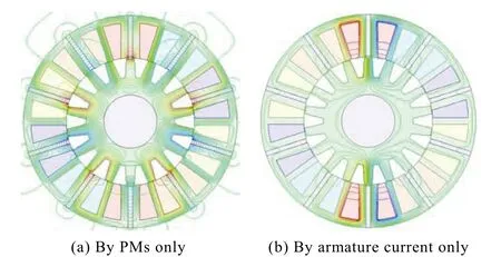
Fig.2 Magnetic field distributions
3 Analysis and control
3.1 Stator-flux orientation
Since the FT-FSPM motor does not generate rotational magnetomotive force(MMF), traditional rotorflux-oriented control strategy cannot be applied to the FT-FSPM motor directly.
In order to enable stator-flux orientated vector control in this FT-FSPM motor, a stator-flux-orienteddqequation of this motor in the rotor reference frame is developed. Fig.3 shows the finite-element method based no-load magnetic field distribution, where the relative positions between thed-axis andq-axis, and the stator teeth and rotor poles are depicted. It can be observed that the rotor position of maximum PM flux linkage is defined as thed-axis, and theq-axis advances thed-axis 90°in electrical degrees (equivalent to 5°in mechanical degrees). The development of thedq-axis is significant for this motor of stator-flux orientated vector control[19].
3.2 Mathematical model
Fig.4 shows the flux linkages of this five-phase FT-FSPM motor, showing that these waveforms are very sinusoidal. The five-phase flux linkageψma,ψmb,ψmc,ψmd,ψmecan be expressed as


Fig.3 No-load field distribution and axis definition

Fig.4 Flux linkage waveforms
whereψmis the magnitude of PMs flux linkage,Prandθrare the rotor pole number and rotor position, respectively.
The stator-flux oriented vector control scheme is based on synchronous rotor reference frames. Hence, the 5-phase stator to 2-phase rotor transformation, i.e., the Park-transformation can be deduced by

According to (1) and (2), the transformed PM flux linkages in rotor reference frame can be indicated as:

From (3), it can be found that the transformedd-axis PM flux linkage,ψmdequals toψm, and theq-axis PM flux linkage,ψmqequals to 0, which is in common in rotor-PM motors. Also, the electrical torque can be deduced as

The above analytical results indicate that the magnetic field due to the magnets in the stator of this five-phase FT-FSPM motor is equivalent to the rotor-PM motors.
3.3 SVPWM for five-phase FT-FSPM motor
Fig.5 shows the topology of a five-phase FT-FSPM motor drive system. The switch-states are defined asSa,Sb,Sc,Sd,Se. Since a five-phase motor has basic voltage vector space and 3rd harmonics space, these two spaces will be analyzed respectively.
In basic voltage vector spaces, when (Sa,Sb,Sc,Sd,Se) = (1, 0, 0, 0, 0), this voltage vector is defined asV16.In the same manner, all of the vectors in basic voltage vector spaces and in 3rd harmonics space can be calculated, as shown in Fig.6. It can be observed that it has 32 voltage vectors in total, namely, 2 zero vectors and 30 non-zero vectors. According to the magnitude,the non-zero vectors can be divided into 3 groups, large vectorsUL= 0.6472Udc, middle vectorsUM= 0.4Udc,and small vectorsUS= 0.2472Udc.


Fig.5 Topology of five-phase FT-FSPM motor drive system
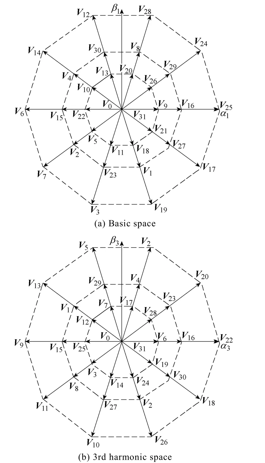
Fig.6 All of basic voltage vectors
3.3.1 Using two neighbouring large vectors
The simplest method to realize a five-phase SVPWM is using two neighboring large vectors and two zero vectors only. The principle of the function time calculation can be described as

When the referenced space vector is in the other sector, the function time can also be calculated by (6).The method of two neighboring large vectors is similar to the traditional three-phase drive technique, which is a simple extension from the three-phase SVPWM.
However, in this method,U24andU25in 3rd harmonics space are small vectors, which are different than in basic space. So, they will synthesis a new non-zero vector. Namely, there will be 3rd harmonics in the stator currents. Consequently, it will lead to torque ripples.
3.3.2 Using four neighboring vectors
The synthesized vector in 3rd harmonics space is zero by adopting four neighboring space vectors in each sector, which can reduce current harmonics and torque ripples. This section adopts SVPWM based on four neighboring vectors.
Fig.7 shows the principle of function time calculation for adopting the four neighboring vectors.In basic voltage vector spaces, Uref is synthesized by the four neighboring vectors, so the equation can be deduced as

In 3rd harmonic space, the synthesized vector is zero, which can be described as

As shown in Fig.6(b),U24andU29,U16andU25are in opposite direction. The synthesized vector is zero in 3rd harmonic space by making their function time in the inverse proportion of their magnitude. The function time ofU16,U24,U25,U29isT1,T2,T3,T4, respectively, whose function time is

According to (7), (8), and (9), the function time for each vector in sector one can be obtained as

wherekis sector number.
When the referenced space vector is in the other sector, the principle of the function time calculation is the same with Fig.7 and (10). Then, the harmonics in stator currents can be reduced and the track effect of flux linkage can be enhanced. The switching sequence in sector one is shown in Fig.8. Similarly, the switching sequences in other sectors can be obtained.
3.3.3 Field oriented control
Fig.9 shows the control block of FOC with adaptingid= 0 method, which is the simplest current control method. It can prevent armature reaction which can produce irreversible PM demagnetization. Ind-qreference frame, the stator current only has AC sections,while the air-gap magnetic field is composed of PMs only. The phasor diagram ofid= 0 control is shown in Fig.10.ψ0is synthesized by PM flux linkage and armature reaction flux linkage.e0is electromotive force and is proportional toψ0.u0is the total electromotive force. The current angleβis zero.
The electrical torque can be described as


Fig.7 The synthesis of four neighboring vectors

Fig.8 Output PWM of sector 1
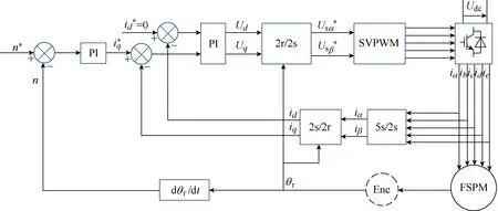
Fig.9 Control block of field oriented control

Fig.10 Phasor diagram (id =0 control)
3.3.4 Direct torque control
The control block of DTC is shown in Fig.11. This scheme employs a space vector to produce continuous voltage vectors, which can adjust the torque and flux more accurately.
Consequently, the torque and flux ripples are reduced, while obtaining fixed switching frequency.In this scheme, two PI regulators and space vector modulation replace the hysteresis controls and switching table in the classical DTC. This proposed scheme has addressed the problems of classical DTC, such as variable switching frequency, torque and flux ripples.The estimation of the stator fluxψsand the torqueTecan be expressed as
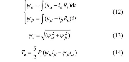
where,uα,uβ,iα,iβ, andRsare theα- andβ- axis voltages,currents and stator resistance, respectively.
Fig.12 is the diagram of flux linkage vectors, the variation of the stator flux and the reference voltage vector in theα- andβ- axis can be obtained as
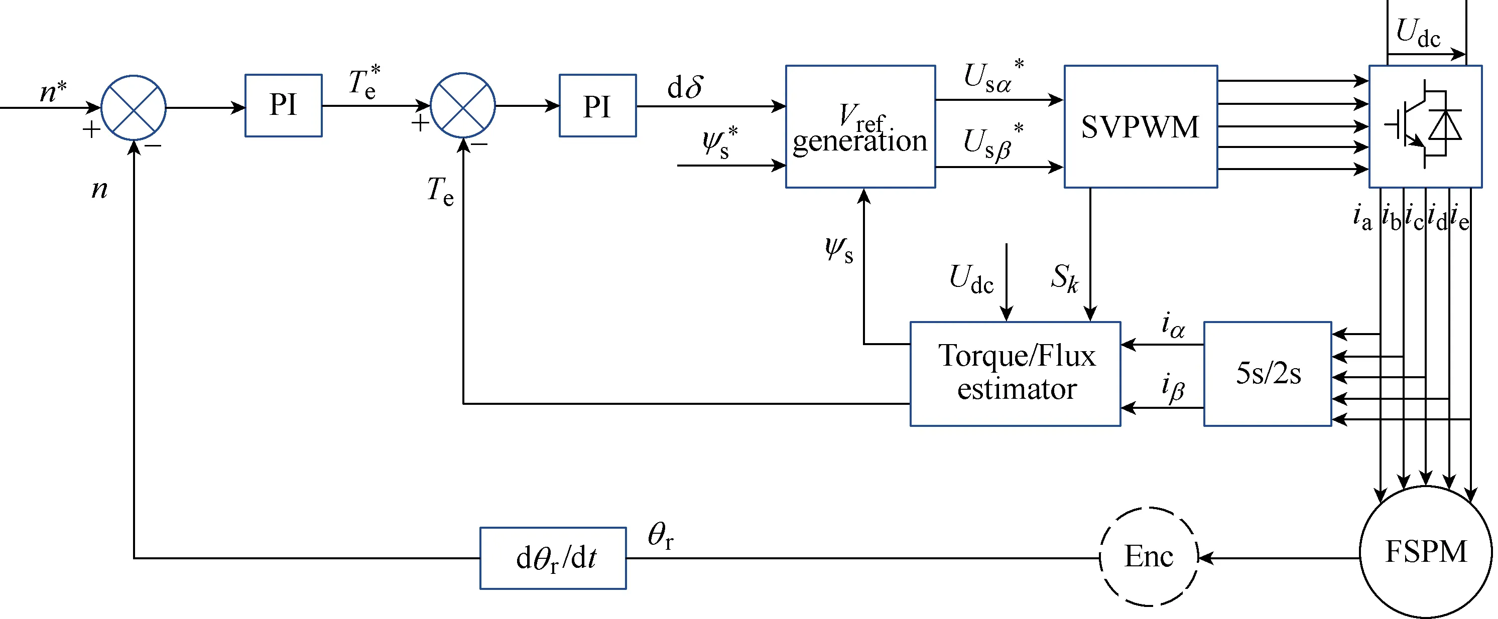
Fig.11 Control block of direct torque control
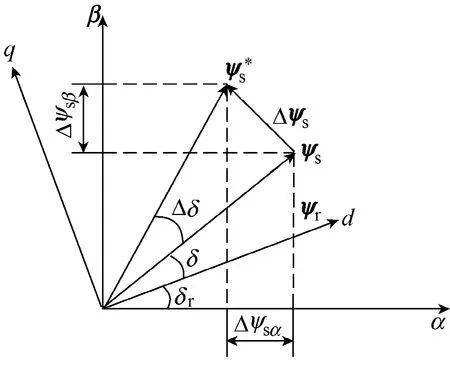
Fig.12 Diagram of flux linkage vectors
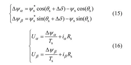
whereTsis the sampling period.
4 Simulation results
The FOC and DTC schemes for this five-phase FT-FSPM motor are simulated by Matlab/Simulink. The parameters of the motor in simulation and experiments are shown in Table 1. The sample time is 100μs, the switching frequency is 10kHz, and the DC bus voltage of power supply is 100V. The reference stator flux linkage is given as 0.06Wb.
The steady-state performance of FOC and DTC schemes for the FT-FSPM motor at 150r/min and 5N·m load are compared in Figs.13 and 14, respectively. It can be seen that the performance of the FOC scheme is better than the DTC scheme. The stator currents have similar performance because they are all sinusoidal and smooth.
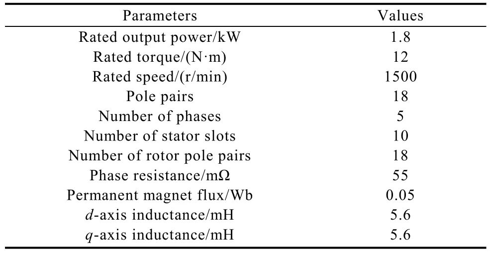
Table 1 Parameters of FT-FSPM motor
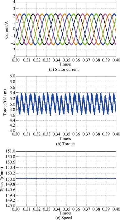
Fig.13 Simulated FOC waveforms in steady-state
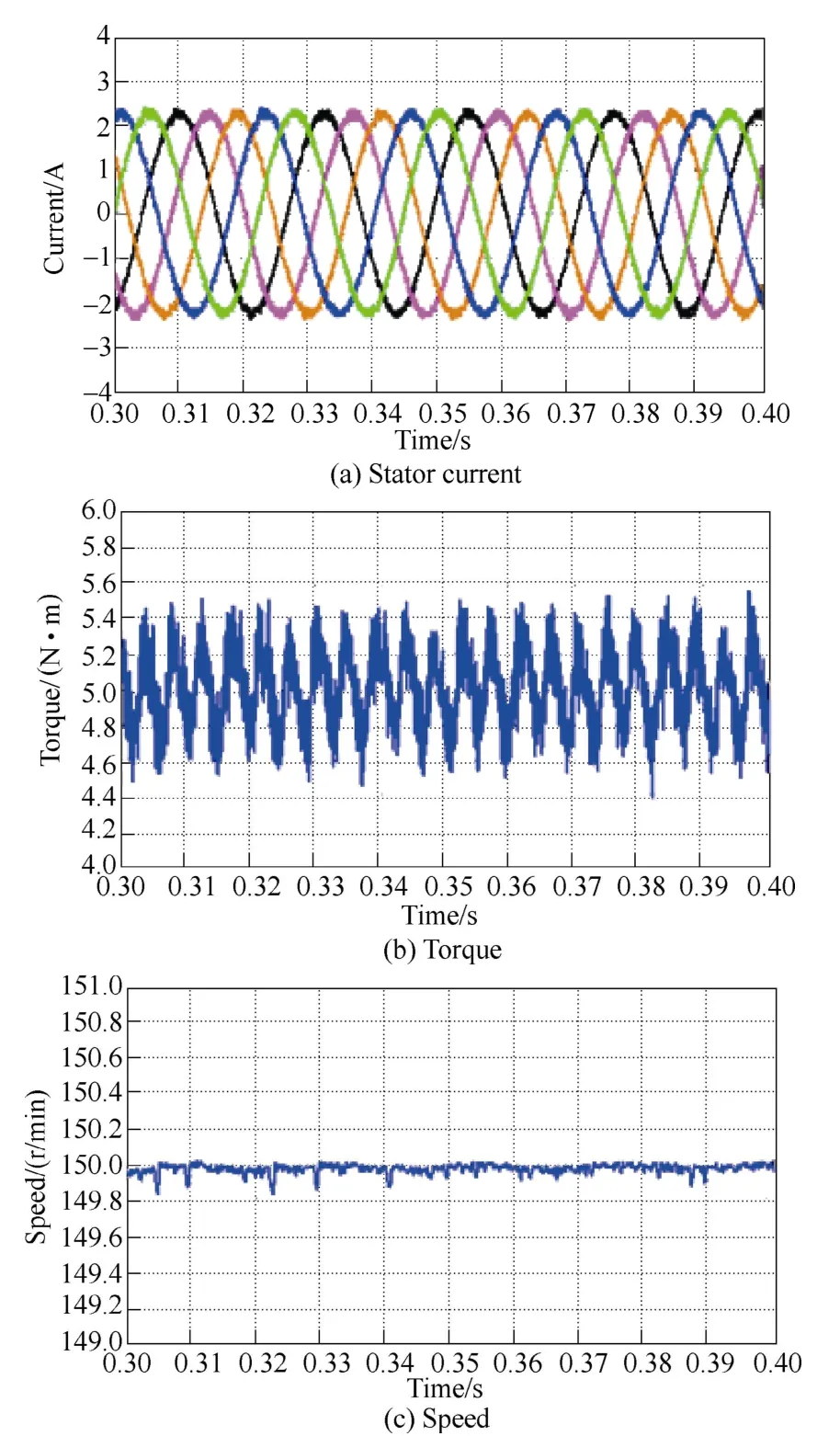
Fig.14 Simulated DTC waveforms in steady-state
The speeds of the two schemes are steady, however,their torque ripples are unsatisfactory. Quantitatively, the torque ripple of FOC is about ±0.4N·m, while that of DTC is about ±0.6N·m. So, the FOC scheme has less torque ripples. Consequently, it can be concluded that the five-phase FT-FSPM motor using FOC scheme has the better steady-state performance.
Figs.15 and 16 compare the transient performances of the two schemes by analyzing the response with a step variation of the torque command from 5N·m to 8N·m. The response time of FOC scheme is about 5ms,and that of DTC is about 2.5ms. In addition, from the torque and speed responses, it can be seen that the DTC scheme has a small pulsation in step variation. Hence, it can be known that DTC scheme have a fast dynamic response in transient-state and well robustness for this five-phase FT-FSPM motor.


Fig.15 Simulated FOC waveforms in transient-state
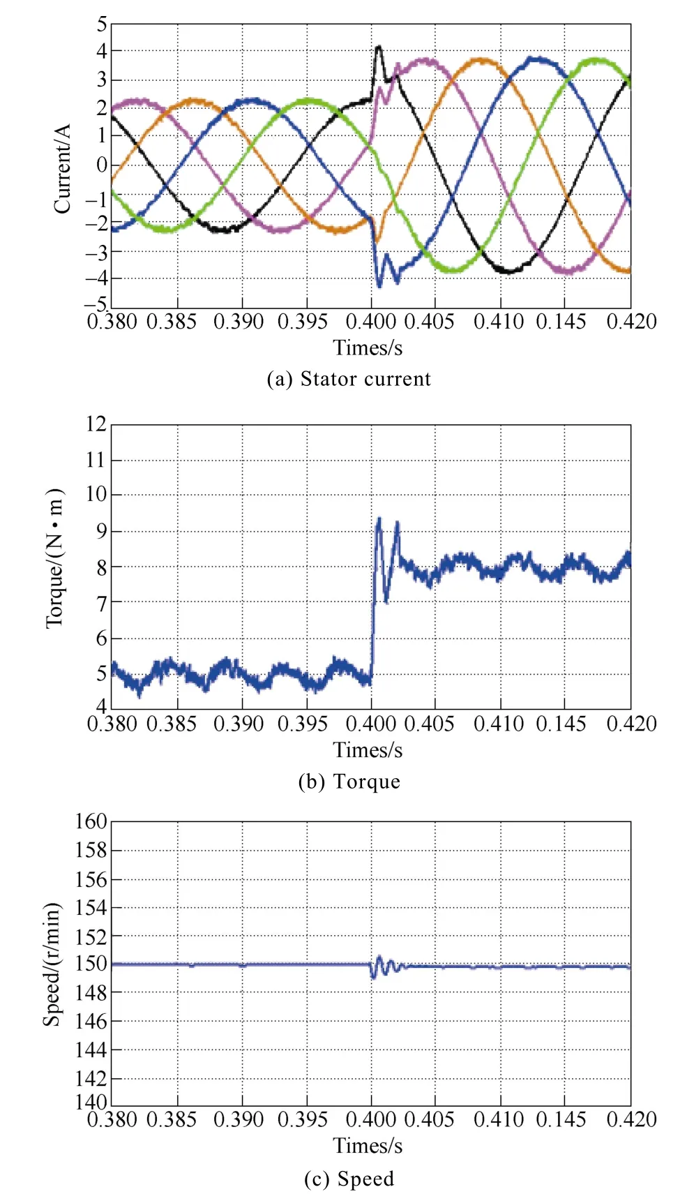
Fig.16 Simulated DTC waveforms in transient-state
5 Experimental verification
To validate the proposed FOC and DTC schemes for the five-phase FT-FSPM motor, an experimental system of the five-phase FT-FSPM motor has been built,as shown in Fig.17. It consists of the torque sensor to measure torque, a magnetic powder brake to offer variable load, TMS320F2812 DSPas the central control chip to implement the control strategy, detection circuit to measure the phase current and voltage, drive circuit to generate PWM signal to control the motor.
Figs.18 and 19 show the experimental results of FOC and DTC schemes at 150r/min and 5N·m load. As expected, the stator current of FOC and DTC schemes have similar performance. Namely, they are all sinusoidal and smooth. The speed of two schemes is also steady.The torque ripple of DTC is about ±2N·m, while that of FOC is about ±1.25N·m. Due to the unbalanced arrangement of phase coils for the FT-FSPM motor and actual manufacturing error, the measured torque ripples are slightly higher. Clearly, the FOC scheme has a better performance than DTC scheme in steady-state.Experimental results are mainly consistent with simulation results.

Fig.17 Expermental setup of control system

Fig.18 Measured torque, speed and current steady-state responses under FOC scheme
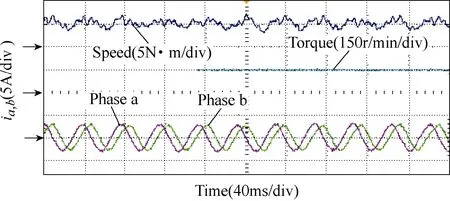
Fig.19 Measured torque, speed and current steady-state responses under DTC scheme
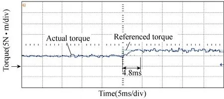
Fig.20 Measured torque transient-state responses under FOC scheme
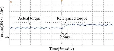
Fig.21 Measured torque transient-state responses under DTC scheme
To validate the dynamic performance of the fivephase FT-FSPM motor at load, it is operated at sudden increasing load conditions. The transient-state performances of FOC and DTC schemes are shown in Figs.20 and 21.It can be seen that when the load increases from 5N·m to 8N·m, the response time of FOC scheme is about 4.8ms and DTC is about 2.6ms. Hence, it can be concluded that DTC scheme has better dynamic response in transientstate for this five-phase FT-FSPM motor.
6 Conclusion
In this paper, SVPWM-based FOC and DTC schemes have been investigated and compared. The structure and electromagnetic performance of a five-phase FT-FSPM motor has been briefly presented. Moreover,itsd- andq- axis have been defined for mathematical modeling. The stator-flux orientated vector control is then derived for this five-phase FT-FSPM motor. The simulation and experimental results indicate that: for this five-phase FT-FSPM motor, the FOC scheme has small torque ripples, and while the DTC scheme has fast dynamic response it also suffers from torque ripples. For further research, sliding mode flux observer, linear quadratic regulator, and duty ratio modulation can be adopted in DTC, improving torque control performance of the motor. Similarly, repetitive control, model reference adaptive control, and predictive control can be adopted in FOC, which improve the dynamic performance of FOC. The two control schemes have their advantages and disadvantages. Hence, according to different needs for a particular application, a preferred scheme can be chosen to be implemented.
 Chinese Journal of Electrical Engineering2018年4期
- Chinese Journal of Electrical Engineering的其它文章
- Research on Clustering Equivalent Modeling of Large-Scale Photovoltaic Power Plants
- No-Load Iron Loss Model for a Fractional-Slot Surface-Mounted Permanent Magnet Motor Based on Magnetic Field Analytical Calculation
- Microgrid Relay Protection Scheme Based on Harmonic Footprint of Short-Circuit Fault
- Study of Pressure Balance for Press-Pack IGBTs and Its Influence on Temperature Distribution
- The Characteristics Analysis and Cogging Torque Optimization of a Surface-Interior Permanent Magnet Synchronous Motor
- Resonance Active Damping and PCC Voltage Quality Improvement of DFIG System Connected to Parallel Compensated Grid
