Resonance Active Damping and PCC Voltage Quality Improvement of DFIG System Connected to Parallel Compensated Grid
Yipeng Song*, Nian Heng2, and Frede Blaabjerg
(1. Department of Energy Technology, Aalborg University, Aalborg East 9220, Denmark;2. College of Electrical Engineering, Zhejiang University, Hangzhou 310027, China)
Abstract: Under the connection to a weak grid, the Doubly Fed Induction Generator(DFIG) based wind power system has potential risk from two operational issues. The first issue is the High Frequency Resonance(HFR) mode due to the impedance interaction between the DFIG system and the weak grid.In order to ensure safe and reliable operation of the DFIG system, it is necessary to implement effective active damping strategies to mitigate the HFR. The second issue is low order voltage harmonic distortion at the Point of Common Coupling(PCC), where consequently the performance of other grid-connected devices may deteriorate. It could be advantageous that the DFIG system is able to improve the voltage quality at PCC by eliminating the low order harmonic components. In this paper, both of the above mentioned DFIG operational characters, i.e., active damping of HFR and the improvement of voltage quality at PCC, will be achieved by implementing advanced control strategies in the Rotor Side Converter(RSC) and the Grid Side Converter(GSC) respectively. Simulations are provided to verify the proposed control strategies for DFIG system connected to a weak grid.
Keywords: DFIG system, weak grid, High Frequency Resonance(HFR), harmonic distortion,active damping.
1 Introduction
The renewable wind power generation technologies have been under rapid development in recent decades,and the most promising wind power solutions include the Doubly Fed Induction Generator(DFIG) based wind turbines and the Permanent Magnetic Synchronous Generator(PMSG) based wind turbines[1-3], which are typically used in wind farms. The DFIG based wind farm has been reported to have certain operational performance advantages over the PMSG based wind farm, i.e., lower converter rating, lower cost and variable speed operation.
However, in practice, the DFIG system may be interfaced with various kinds of non-ideal grid voltage conditions, and its performance may deteriorate accordingly. In order to improve the DFIG system performance under non-ideal grid voltage conditions,several improved control strategies have been demonstrated, including grid low voltage fault ride-through technology[4], virtual inertia control for grid frequency support[5], improved control strategy under grid voltage steady-state three-phase unbalance[6-7]and harmonic distortion[8], and a novel topology of DFIG connected to a DC-grid through the stator winding using a diode rectifier[9].
In addition to the studies mentioned above, there are also two further issues, which require careful attention for the DFIG system connected to the weak grid.
Firstly, the DFIG system is likely to operate under the connection of the weak grid, which has a larger impedance than the stiff grid. As reported in [10-18], due to the impedance interaction between the DFIG system and the weak grid, the High Frequency Resonance(HFR)could be a potential operational threat, and consequently the output wind power quality worsens with the abundant amount of harmonically distorted current injected to the grid. Also, electromagnetic torque pulsations may result in damage of the mechanical components such as bearing and shaft. In order to ensure the reliable operation of the DFIG system as well as to improve the output wind power quality, it is necessary to implement effective active damping strategies to mitigate the HFR.
Secondly, in the case of the weak grid condition,the non-linear load may be widely applied, and the voltage low order harmonic distortion at the Point of Common Coupling(PCC) could occur. Consequently, the performance of the other grid-connected power converters may be jeopardized due to these low order harmonic distortions. It could be advantageous that the DFIG system is able to improve the voltage quality at PCC by eliminating the low order harmonic components[19-21].
The main contribution of this paper is to solve these two issues: the active damping of the HFR and the improvement of the voltage quality at PCC. Considering that the DFIG system has both the Rotor Side Converter(RSC) and the Grid Side Converter(GSC), the active damping control strategy is implemented in the RSC by introducing a virtual impedance to effectively reshape the DFIG system impedance and to mitigate the HFR; on the other hand, the Grid Side Converter(GSC) introduces a closed-loop control of the PCC voltage using the 300Hz resonant controller to eliminate the lower order(5th and 7th) harmonic components at the PCC voltage.
Note that both of these two issues are related to the impedance of the weak grid. For the HFR issue, it is caused by the impedance interaction between the DFIG system and the weak grid, while for the PCC voltage harmonic distortion issue, it can be improved by injecting the low order harmonic current of the same amplitude but in the opposite phase, so that the voltage drop across the weak grid impedance cancels off the low order voltage components at PCC.
This paper is organized as follows: the impedance modeling of the DFIG system and the parallel compensated weak grid are firstly described in Section 2.On this basis, the HFR phenomenon due to the impedance interaction between the weak grid and the DFIG system is analyzed using the Bode diagram method. Thereafter the HFR active damping strategy is given in Section 3. Moreover, the PCC voltage harmonic distortion is removed by including the PCC voltage closed-loop control in the GSC in Section 4. The simulation of 7.5kW small scale DFIG system is provided in order to validate the proposed control strategies in Section 5. Finally, the conclusions are given in Section 6.
2 System configuration and impedance modeling of DFIG system
The general description of the DFIG system is necessary for the following discussion, and the impedance modeling of both the DFIG system and the parallel compensated weak grid[10-14]need to be explained in this section.
2.1 General description of the DFIG system
The configuration of the investigated DFIG system and the parallel compensated weak grid is shown in Fig.1. Both the Rotor Side Converter(RSC) and the Grid Side Converter(GSC) adopt the Vector Oriented Control(VOC) in the synchronous frame. The RSC implements the rotor currentIrclosed-loop control using PI controller in order to deliver the DFIG stator active and reactive power as clean and renewable wind power. On the other hand, the GSC employs the DC-link voltageVdcouter-loop control and the filter currentIfinner-loop control for the purpose of providing the stable dc-link voltage and adjusting the power factor.
The switching harmonics are eliminated by adopting the LCL filter. The three-terminal step-up transformer TDFIGis connected between the DFIG stator winding,the LCL output terminal and the Point of Common Coupling(PCC) for adjusting the voltage level of the DFIG system. In this paper, a small scale 7.5kW DFIG system, which may be commonly seen in the application of micro-grids, is adopted under the investigations, and the parameters are shown in Table 1.

Fig.1 Configuration of the DFIG system connected to a parallel compensated weak grid

Table 1 Parameters of the small scale 7.5kW DFIG system
A parallel compensated weak grid includes the grid inductanceLNETand the grid resistanceRNETin a series connection, and the grid shunt capacitanceCNETconnected between the transmission cables and the ground, which exists due to the parasitic capacitance between the cable and ground or due to the passive power factor correction devices.
2.2 Impedance modeling of the DFIG system
The grid part of the DFIG system consists of the GSC and the LCL filter, its per-phase impedance modeling[10-14]is presented in Fig.2, and the impedance equation of the DFIG grid side can be obtained as,

where, the LCL-filter related components areZCf=1/sCfandCfis capacitance;ZLf=sLfandLfis the converter side inductance;ZLg=sLg andLg is the LCL grid side inductance.K1=VPCC/VGis the voltage ratio betweenVGandVPCC. The GSC PI current controller impedance is defined asZGSC= Gc(s-jω0)Gd(s-jω0).Gc(s-jω0)includes the proportional partKpgscand the integral partKigsc/(s-jω0), which can be found in Table 1.Gd(s-jω0)is the digital control delay of 1.5 sample period caused by the delay of sampling and PWM update[10-14]. The grid fundamental angular speedω0=100πrad/s is introduced due to the reference frame rotation from the stationary frame to the synchronous frame. Note that the control loop of the DC-link voltage and the grid synchronization in the GSC are neglected due to the slower dynamic response[10-14].
The per-phase impedance of the RSC and DFIG machine[10-14]can be obtained in Fig.3 as,

where,H=ZLσr+(Rr+ZRSC)/slip,the impedance of the RSC PI current controller is defined asZRSC=Gc(s-jω0)Gd(s-jω0). The impedance of the DFIG machine is defined as,ZLm=sLmandLmis the mutual inductance;ZLσr=sLσrandLσris the rotor leakage inductance;ZLσs=sLσsandLσsis the stator leakage inductance,Rris the rotor resistance.K2=VPCC/VSis the voltage ratio betweenVSandVPCC., The rotor current needs to be transformed into the rotor stationary frame since it is controlled in the synchronous reference frame,using the slip angular speed expressed as [10-14],

where,ωris the rotor angular speed.
Since the RSC and DFIG machineZSRand the GSC and LCL-filterZGare connected in parallel as shown in Fig.1, the DFIG system impedanceZSYScan be obtained based on (1) and (2) as,

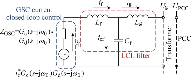
Fig.2 Impedance modeling of the Grid Side Converter(GSC)equipped with LCL filter
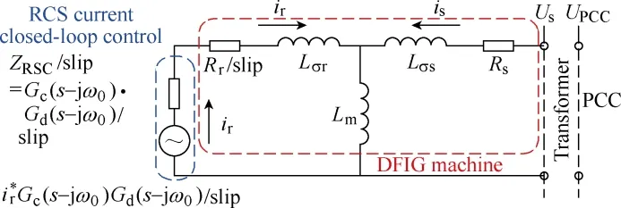
Fig.3 Impedance modeling of the DFIG machine and Rotor Side Converter(RSC)
2.3 Impedance modeling of the parallel compensated weak grid
According to Fig.1, the impedance modeling of the parallel compensated weak grid[10-14]can be deduced as,

where,RNET,LNETandCNETare the grid resistance,inductance and capacitance respectively.
2.4 Short Circuit Ratio(SCR) of the grid
As commonly known, the Short Circuit Ratio(SCR)is adopted to evaluate the stiffness/weakness of certain grid conditions. It is applicable for the case of series RL grid impedance, while for the case of grid equipped with series RL and parallel C together as discussed in this paper, the Effective SCR(ESCR)[23]needs to be introduced as below,

where,SSCis the apparent power capacity when the short circuit happens,Qcis the reactive power of all the shunt capacitances between a wind farm and a PCC,Pnis the rated power of the wind farm. Compared with the definition of the conventional SCR, the ESCR takes into consideration the shunt capacitance, and thus it is more accurate to evaluate the grid stiffness in this paper.
By substituting the system parameters listed in Table 1 into Eq.(6), i.e.,SSC=336.9kVA,Qc=996var andPn=7.5kW, the ESCR value can be calculated as ESCR=45. Thus, it can be found that the stiffness of the grid under discussion in this paper is somewhere between a stiff grid (which has the SCR larger than 300)and a weak grid (which has the SCR smaller than 30).Considering that the grid impedance, including both series RL and parallel C, causes the operational issues of both the HFR and the voltage harmonic distortion elimination, it is decided that the grid under discussion will still be defined as a weak grid.
3 HFR analysis and active damping
3.1 Analysis of HFR using Bode diagram
The Bode diagram based analysis method is adopted to discuss the HFR in the previous works[10-14]. The method first plots the Bode diagram impedance curves of the DFIG system and the parallel compensated weak grid, and then evaluates if the phase difference at the magnitude intersection point between the DFIG system and the weak grid is equal or larger than 180°[10-14].
The analysis on the HFR is conducted based on the 7.5kW DFIG system and the parallel compensated weak grid as shown in Fig.4. As can be seen, the impedance curves of the DFIG system and the parallel compensated weak grids have the magnitude intersection point at 1140Hz whenCNET= 22μF, 1177Hz whenCNET= 20μF,1223Hz whenCNET=18μF, and the weak grid inductance is kept constant asLNET=1.5mH. The phase differences at these frequencies are all 180° and will result in the occurrence of the HFR at these frequencies.
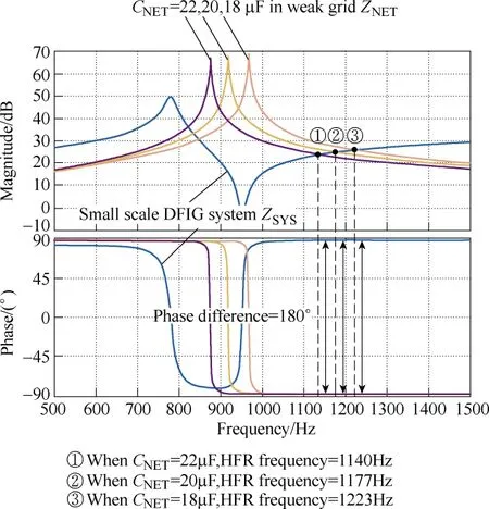
Fig.4 Analysis of HFR between the 7.5kW DFIG system and the parallel compensated weak grid using the Bode diagram method
Although there are several magnitude intersection points located between 800Hz and 900Hz, the phase difference at these frequencies are smaller than 180°,and therefore there are no HFR at these frequencies.
3.2 Active damping of HFR
As reported in [12], the active damping strategy aims to insert the virtual impedance into the DFIG system so that the impedance characteristic of the DFIG system is modified appropriately, and the HFR can be mitigated accordingly.
The virtual impedance inserted into the DFIG stator branch using a combination of a high-pass filter and virtual positive capacitor or negative inductor is adopted[12]. Since this active damping strategy has been demonstrated in detail in [12], only a brief introduction will be given here. The virtual impedanceZv(s) can be expressed as below,

where,fcutis the cutoff frequency of the high-pass filter,which is designed asfcut=500Hz since it is expected to damp the resonance at the higher frequency range.Td=150μs is the inevitable digital control delay caused by sampling and PWM update rate.Rvis the virtual positive resistance to adjust the magnitude of the virtual impedance.
Fig.5 demonstrates the control scheme of the DFIG RSC, including ① fundamental closed-loop control of the rotor current for normal output wind power; ② the active damping control strategy through the insertion of virtual impedance in the DFIG stator branch. The fundamental control adopts the rotor currentdq-axis components regulation using PI controller in order to deliver the expected wind power to the utility grid. On the other hand, the stator current based feedforward control including the virtual impedance is also employed,and the DFIG system impedance character can be reshaped accordingly.
Fig.6 shows the Bode diagram of the HFR active damping analysis when the virtual impedance is inserted in the stator branch,fcut= 500Hz,Rv= 50Ω,Td= 150μs.As can be seen, once the virtual impedance based active damping is implemented, the DFIG system impedance is significantly reshaped in terms of the phase character.The phase can be decreased by around 20 degree at the potential resonance frequency from 1kHz to 1.5kHz.This phase margin can help to damp the resonance due to the equivalent positive resistance of the DFIG system.For the specific resonance case as shown in Fig.6, the original HFR at 1170Hz can be damped since the phase difference between the weak grid and the DFIG system can be reduced to 160 degree when adopting the virtual impedance in the stator branch.
4 PCC voltage quality improvement
The voltage at PCC in a weak grid may be polluted by low order harmonic components due to the operation of the non-linear load and etc. As a consequence, the distorted PCC voltage may jeopardize the performance of other power converters connected to the weak grid as well. Thus, it is necessary to improve the voltage quality at PCC by implementing certain advanced control techniques in the DFIG system.
Fig.7 shows the scheme of the PCC voltage quality improvement using the DFIG system harmonic current injection. As can be seen, the grid voltage at PCC may contain the 5th and 7th low order harmonics components as the background harmonic pollution. In order to compensate these harmonics at PCC, the DFIG system should be able to inject a certain amount of harmonic currents, and the voltage drops over the weak grid impedance, i.e., theLNETandRNET, include the 5th and 7th harmonics component with the same amplitude but the opposite phase compared with the PCC voltage harmonics, thus the low order harmonics at PCC can be cancelled off.
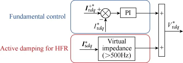
Fig.5 Control scheme of the DFIG RSC
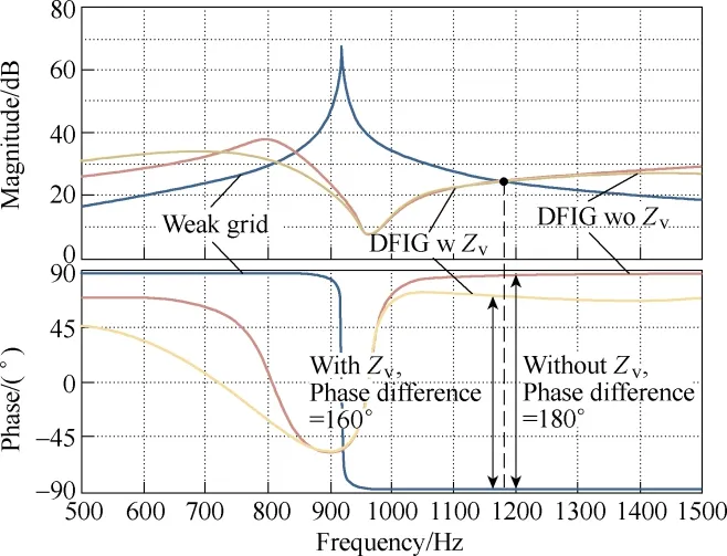
Fig.6 Bode diagram of the HFR active damping analysis when the virtual impedance is inserted in the stator branch(fcut=500Hz, Rv=50Ω, Td=150μs)
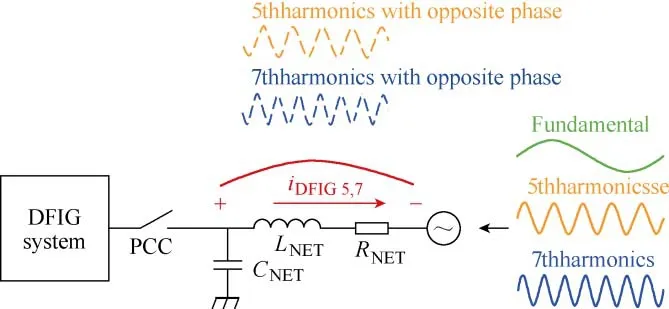
Fig.7 Scheme of the PCC voltage quality improvement using the DFIG system harmonic current injection to compensate for voltage background distortion
Fig.8 shows the control scheme of the PCC voltage quality improvement strategy with the mitigation of the 5th and 7th harmonics components. The fundamental control of GSC includes the outer-loop control of the DC-link voltageVdc, and also the inner-loop control of the LCL filter side currentIfdq. On the other hand, the harmonics mitigation of PCC voltage is achieved through the closed-loop control ofUPCC. In order to mitigate the low order harmonics, the control reference is set to zero. Note that the 5th and 7th low order harmonics behave as 300Hz AC components in the synchronous frame, thus the resonance controller tuned at 300Hz is adopted. Finally, the GSC output voltage will contain the 5th and 7th harmonic components which generate the 5th and 7th harmonic currents, and thereafter produce the harmonic voltage drops across the weak grid impedance cancelling off the low order harmonics at PCC.
The resonant controller tuned at 300Hz can be expressed as below[22],
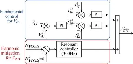
Fig.8 Control scheme of the DFIG GSC

where,ω0is the resonant frequency set asω0=2π×300rad/s,ωcis the resonant bandwidth parameter, which is normally set asωc=5rad/s. Note that the resonant controller is only able to regulate the 300Hz AC error,but neglect the DC error, therefore only the 300Hz AC component will be produced as the resonant controller output.
5 Simulation validation
In order to validate the proposed improved control strategy for the DFIG system using both HFR damping and PCC voltage quality improvement, simulations of 7.5kW DFIG system based on Matlab/Simulink are done.
5.1 Control diagram
Fig.9 shows the control diagram of the DFIG system with its parameters listed in Table 1. The grid voltage fundamental synchronous angular speedω1and angleθ1can be acquired using a Phase Locked Loop(PLL), and an encoder gives out the DFIG rotor positionθrand speedωr.

Fig.9 Control diagram of the DFIG system including the parallel compensated weak grid
The rotor currentis sampled and controlled based on the referenceusing a PI controller. Then,the rotor control voltagecan be calculated as the sum of the output of the rotor current PI closed-loop controland a decoupling compensation, the rotor control voltageis then transformed to the rotor stationary frame and delivered as the input to the Space Vector Pulse Width Modulation(SVPWM).
As for the GSC control, the dc-link voltageVdcis regulated by a PI controller, and its output is delivered as the reference of the converter side inductor current, which is used to regulate the converter side inductor currentusing a PI controller. Then the GSC control voltagecan be obtained as the sum of the PI controller outputand the decoupling compensation unit.
5.2 Simulation results
Fig.10 shows the simulation results of the DFIG system HFR under the weak grid ofRNET=30mΩ,LNET=1.5mH,CNET=22μF, (b) 20μF and (c) 18μF respectively.As shown in Fig.10, the HFR occurs for all these three cases. The resonance frequencies of HFR, according to the FFT analysis of PCC voltageUPCC, are respectively 1180Hz: 23.7%, 1200Hz: 37.0% and 1240Hz: 109.1%.These HFR simulation results correlate very well with the theoretical analysis of the Bode diagram based impedance in Fig.4.
All the voltages and currents in the DFIG stator and rotor windings, as well as the grid side voltage and current, contain the resonance components. Consequently,the output wind power quality deteriorates severely due to the high amount of harmonic distortion, and the mechanical components, including the bearing and shaft,are also jeopardized due to the risk electromagnetic torque pulsation.
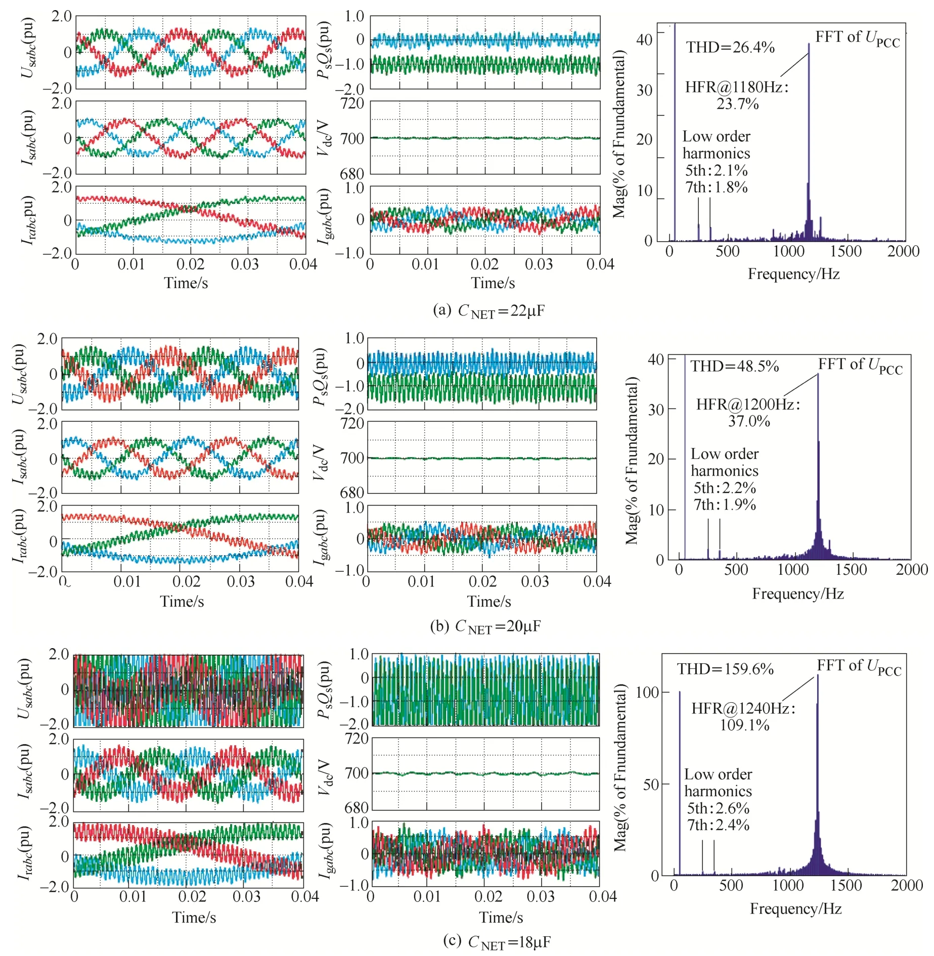
Fig.10 Simulation results of the DFIG system HFR under the weak grid of RNET = 30mΩ, LNET = 1.5mH
Moreover, the FFT analysis ofUPCChelps to prove the existence of the grid voltage background low order 5th and 7th harmonics components. Note that these low order harmonic components have inherent differences compared with the HFR resonance harmonics, i.e., the low order harmonics are produced due to the adoption of non-linear devices, and can be regarded as the background harmonics pollution of the power grid; on the other hand, the resonance harmonics are produced due to the impedance interaction between the DFIG system and the weak grid. In conclusion, these two harmonics occur at the same time in the grid voltage, but are essentially independent to each other.
Fig.11 shows the simulation results of the DFIG system under different operation modes, i.e., Phase I:conventional control, Phase II: active damping control,and Phase III: both active damping control and PCC voltage improvement control. During Phase I the conventional control is employed and the severe HFR harmonics and low order 5th and 7th harmonics occur;while during Phase II when the active damping control is enabled, the HFR resonance components in all the stator voltageUsabc, stator currentIsabc, rotor currentIrabcand GSC currentIgabccan be well eliminated, while the low order 5th and 7th harmonics still exist. Furthermore,when both the active damping andUPCCimprovement control are adopted during Phase III, the voltage quality at PCC (or stator voltage) can be enhanced by eliminating the low order 5th and 7th harmonic components. The PCC voltage 5th and 7th harmonic component before enabling the quality improvement strategy are 2.1% and 1.9% respectively, while they are 0.7% and 0.6% after enabling the quality improvement strategy. However, it should be pointed out that theUPCCimprovement is achieved by injecting harmonic current with opposite phase angle through the GSC and therefore the quality of GSC currentIgabcdeteriorates with higher harmonic distortion.
Based on the above simulation results, the effectiveness of the proposed control strategy for DFIG considering both the HFR active damping and the PCC voltage quality improvement has been verified.Therefore, the output wind power quality can be enhanced by active damping, and the performance of other grid-connected devices can simultaneously be improved due to the sinusoidal PCC voltage.
6 Conclusion
This paper has proposed an improved control strategy for a DFIG system considering both the HFR active damping and the improvement of PCC voltage quality. The HFR active damping control is successfully implemented in the RSC by inserting a virtual impedance through the stator current feedforward control. Also a PCC voltage quality improvement is achieved in the GSC through the closed-loop control of PCC voltage using a 300Hz resonant controller. Finally,the high frequency harmonics caused by the DFIG HFR and the grid voltage background low order harmonics are inherently independent and can therefore be controlled independently.
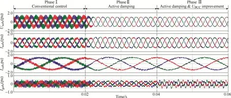
Fig.11 Simulation results of the DFIG system under Phase I, Phase II, and Phase III
 Chinese Journal of Electrical Engineering2018年4期
- Chinese Journal of Electrical Engineering的其它文章
- Battery Charging Method for Electric Vehicles:From Wired to On-Road Wireless Charging
- Using Inverter-Based Renewable Generators to Improve the Grid Power Quality—A Review
- Review of Power Decoupling Methods for Micro-Inverters Used in PV Systems
- The Characteristics Analysis and Cogging Torque Optimization of a Surface-Interior Permanent Magnet Synchronous Motor
- Field-Oriented Control and Direct Torque Control for a Five-Phase Fault-Tolerant Flux-Switching Permanent-Magnet Motor
- Study of Pressure Balance for Press-Pack IGBTs and Its Influence on Temperature Distribution
