No-Load Iron Loss Model for a Fractional-Slot Surface-Mounted Permanent Magnet Motor Based on Magnetic Field Analytical Calculation
(Schoolof Electrical Engineering and Automation, Harbin Institute of Technology, Harbin 150006,China)
Abstract: The common analytical models for the no-load iron loss of permanent magnet(PM)motors usually neglect the iron loss caused by the rotating magnetic field in the tooth tips and the harmonics of the magnetic fields in the teeth and yokes. This paper presents an analytical model for no-load iron loss of a fractional-slot surface-mounted permanent magnet motor. According to the existing analytical model of the magnetic field distribution in the slotted air gap, the magnetic flux densities considering the harmonics of the stator tooth and yoke are both derived based on the continuity of magnetic flux. Due to the complexity of the magnetic field in the tooth tip, the tangential flux density of the tooth tip is approximated by an equivalent sine wave and the radial component is regarded to be the same as that of the corresponding tooth. After obtaining the magnetic fields in stator different regions, the analytical iron loss is calculated by using the Bertotti model and the orthogonal decomposition model. A 20-pole/24-slot PM synchronous motor is taken as an example. The maximum error between the analytical model and finite element model(FEM) is 5.46%, which verifies the validity of the proposed method.
Keywords: No-load iron loss, fractional slot, permanent magnet motors, magnetic fields,orthogonal decomposition model.
1 Introduction
Iron loss is a main component of the total loss of the PM motors. Accurate prediction of the iron loss is the premise of optimizing motor efficiency and temperature rise. Although the FEM is more effective in the calculation of the iron loss[1], it is not convenient to be used in the primary design stage. Therefore, an analytical model of the iron loss is necessary for the PM motor design.
Using either the FEM or the analytical model to calculate the iron loss, the premise is to obtain the magnetic fields in the stator core. For the analytical model, there are usually two ways to obtain the magnetic fields in the stator core. One way is to calculate the magnetic fields of the different stator regions according to the continuity of magnetic flux based on the existing analytical expression of the air-gap magnetic flux density[2-3]. Reference [2] derived the air-gap magnetic field of the spoke-type permanent-magnet synchronous machines. The average magnetic flux densities of the teeth and yokes were then obtained by integrating the air-gap magnetic field. The analytical model was in good agreement with the FEM. However,no specific expressions for the magnetic fields of the teeth and yokes were given. Reference [3] derived the magnetic flux densities of the tooth, yoke and tooth tip for a short-stroke single-phase tubular PM machine.However, the analytical model is not compared with the FEM. The other way is to build the equivalent magnetic circuit of the motor and obtain the magnetic flux density of each node in the stator core directly[4-5]. Reference [4]built an equivalent magnetic circuit of the interior permanent magnet synchronous machine. The magnetic flux density of the tooth was directly obtained by solving the nonlinear magnetic circuit with an iterative method. The load magnetic density of the tooth in analytical model coincides well with that in the FEM.Because of the irregular shape of the stator yoke, the magnetic field of the yoke is not introduced. An armature reaction magnetic circuit was built in reference[5]. The study showed that the amplitude of the load flux density of the stator yoke is different due to the winding configuration of the fractional-slot motor. The fundamental flux density of the yoke was derived, while the harmonics were neglected.
The magnetic field in the tooth tip of a fractionalslot surface-mounted PM motor is the rotating magnetic field due to the zigzag leakage flux. Most analytical models only consider the iron loss caused by the radial magnetic field in the teeth, while the loss caused by the tangential magnetic field in the tooth tips is neglected.The distribution of the magnetic field in the tooth tip is more complicated than those in the teeth and yokes.To the author’s knowledge, none of the pre-existing analytical methods can predict the magnetic flux density of the tooth tip well. Reference [6] built an analytical model where the zigzag leakage flux is an approximately triangular wave with time. Reference [7] predicted the magnetic flux of the tooth tip changing with time accurately, but did not discuss the flux density of the tooth tip more deeply. In reference [8], a search coil was placed on the tooth tip of the prototype. Then the magnetic flux was obtained by integrating the back electromotive force measured by the search coil. As the search coil “saw” only the radial component, thus, the tangential component of the flux density was not measured. As well, the study in [8] showed that the zigzag flux leakage causes high iron losses in the tooth tips that represent around 50% of the stator iron losses under field weakening operation. In reference [3], both the radial and axial flux density waveforms of the tooth tip were approximated as trapezoidal, and the transition time of the trapezoidal flux density waveform is given by an empirical equation.
After obtaining the distribution of magnetic field in the stator core, the iron loss can be calculated according to the iron loss formula. The magnetic field in stator core can be divided into two types: alternating magnetic field and rotating magnetic field. For alternating magnetic field, the iron loss can be accurately calculated by the Bertotti model[9]. For rotating magnetic field, the common iron loss models include the elliptical rotation model[10]and the orthogonal decomposition model[11-12].Before the calculation of the elliptical rotation model,the corresponding loss coefficient should be obtained by curve-fitting the loss data of ferromagnetic materials under rotating magnetization[13]. The loss data obtained from manufacturers are usually tested by the Epstein test apparatus which only applies the alternating magnetization. Thus, the loss data under rotating magnetization usually need to be measured by ourselves.Although the elliptical rotation model can predict the iron loss very well, it is not very suitable for the motor design stage. Therefore, some scholars have decomposed the rotating magnetic field into two orthogonal alternating magnetic fields to calculate the iron loss respectively by means of the Berttoti model, and the two iron losses are superposed to approximate the iron loss under the rotating magnetization. As the alternating magnetization and rotating magnetization are two different physical processes, there is no physical basis for equivalent rotating magnetic field by orthogonal alternating magnetic fields. Therefore, the orthogonal decomposition model is only a mathematical method.However, this model saves a lot of work needed to build test apparatus, and is relatively simple to implement.
In this paper, based on the existing analytical model of the magnetic field distribution in the slotted air gap,the specific expressions of the magnetic flux densities considering the harmonics in the stator teeth and yokes are both given according to the continuity of magnetic flux. Due to the irregular shape of the tooth tip, the tangential flux density of the tooth tip is approximated by an equivalent sine wave and the radial component is regarded to be the same as that of the corresponding tooth. The Bertotti model is used for the iron loss of teeth and yokes, and the orthogonal decomposition model is applied for the iron loss of tooth tips. An FEM of a 20-pole/24-slot PM synchronous motor is simulated to verify the validity of the proposed method.
2 Magnetic field in the slotted air gap
2.1 Magnetic field in the slotless air gap
The magnetic field in the slotless air gap of a surface-mounted permanent magnet motor has been presented in [14]. Therefore, the no-load flux density in a slotless air gap in the case of radial magnetization are directly quoted by (1)-(4) in this paper, whereBris the magnet remanence,μris the relative recoil permeability,αis the polar arc coefficient,pis the pole pair,ωrmisthe mechanical angular velocity,Rsis the stator inner radius,Rmis the magnet surface radius, andRris the outer radius of the rotor core.

where

The radial and tangential components are both given in the form of a finite Fourier series to facilitate the subsequent calculation of magnetic field in the stator core[15].
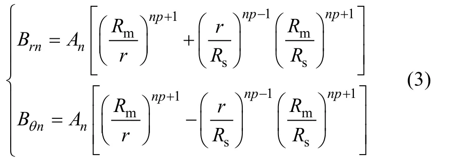
where

2.2 Complex relative air-gap permeance
The notion of complex relative air-gap permeance is usually introduced to consider the effect of slotting on the air-gap magnetic field. Then the magnetic field in the slotted air gap can be calculated as follows.

whereλis the complex relative air-gap permeance[15].
To obtain the complex relative air-gap permeance,the slotted air gap needs to be transformed into the slotless air gap by four conformal transformations. They are expressed as (6) and (7), whereθsis the slot pitch angle,θ1andθ2are the angles on both sides of the slot opening[3]which are shown in Fig.1.
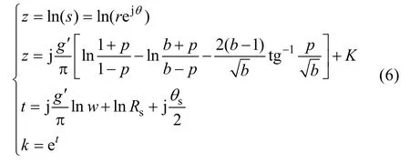
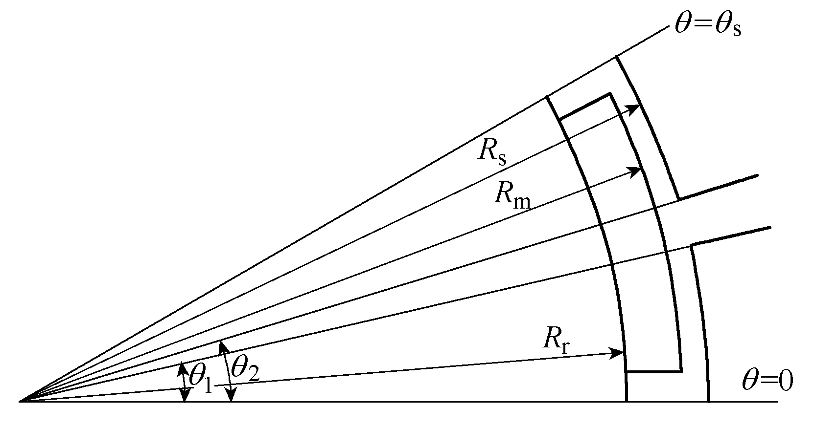
Fig.1 Dimensions of slot-opening
where
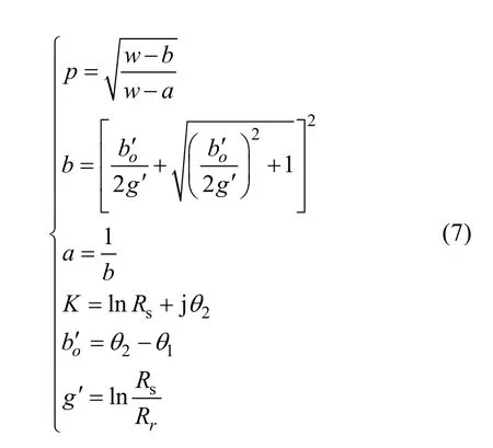
Since the derivations of the conformal transformations have already been presented in detail in [15], they will not be covered here. According to (6) and (7), the complex relative air-gap permeance can be obtained.

As the complex relative air gap permeance is a complex number, it can also be written as follows.

To facilitate the following derivations, the radial and tangential components also need be written in the form of a finite Fourier series in the entire air gap.

whereQsis the slot number,λ0is the constant term,λanandλbnare the harmonic amplitudes of the radial and tangential components. (10) can be obtained by discrete Fourier transform(DFT). Then the magnetic field in the slotted air gap can be expressed according to (5).

3 Magnetic field in the stator core
3.1 Magnetic field in the tooth
The coordinate origin ofBkis the center line of the N pole, and the coordinate origin ofλis the center line of the tooth which is defined as No.1. As shown in Fig.2(a), it is set that the two center lines are aligned when the time is 0. At this moment, the tooth flux reaches the maximum value.
Since only the radial component of air gap magnetic density is effective in calculating the magnetic field in the iron core, the tangential component is not discussed here. Then the radial component can be expanded as follows.
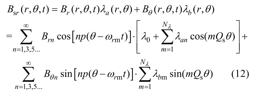
It is assumed that the radial air gap flux under one slot pitch all flows into the corresponding tooth. Then the flux in the tooth can be obtained by integrating the air-gap flux density in one slot pitch.

whereRis the radius close to the stator surface andγsis the slot pitch angle.

After integration the expression is obtained.

where

It is assumed that the magnetic field in a tooth is evenly distributed. Then the average flux density of the tooth 1 can be calculated.

where

Then the flux density of themth tooth is deduced.

3.2 Magnetic field in the yoke
For fractional-slot motors, because the number of poles and slots are similar, the flux in the teeth is usually shunted to the adjacent yokes. Therefore, compared with integral-slot motors, the fractional-slot motors have thinner yoke.
In this paper, it is approximated that the maximum yoke flux is half of the maximum tooth flux. As shown in Fig.2(b), when the center line between the N pole and the S pole is aligned with the slot opening, the flux of the yoke which is defined as No.1 reaches the maximum value. According to the analysis before, it can be seen that there is a fixed phase difference between the tooth flux and the yoke flux.
It is assumed that the magnetic field in a yoke is evenly distributed. Then the flux density in themth yoke is deduced.

where

3.3 Magnetic field in the tooth tip
This paper assumes that the radial component of the flux density of the tooth tipBsttris the same as that of the same toothBstand the tangential componentBstttis approximated by an equivalent sine wave. As shown in Fig.2(c), when the center line between the N pole and the S pole is aligned with the tooth axis, the flux of the tooth tip which is defined as No.1 reaches the maximum value. Then the tangential flux density of themth tooth tip can be obtained.

wherehs0is the height of the slot opening,hs1is the height of the slot shoulder, and thebstis the tooth width.

whereγpis the pole pitch angle.


Fig.2 Peak flux time of tooth 1, yoke 1 and tooth tip 1
After integration the expression is obtained.
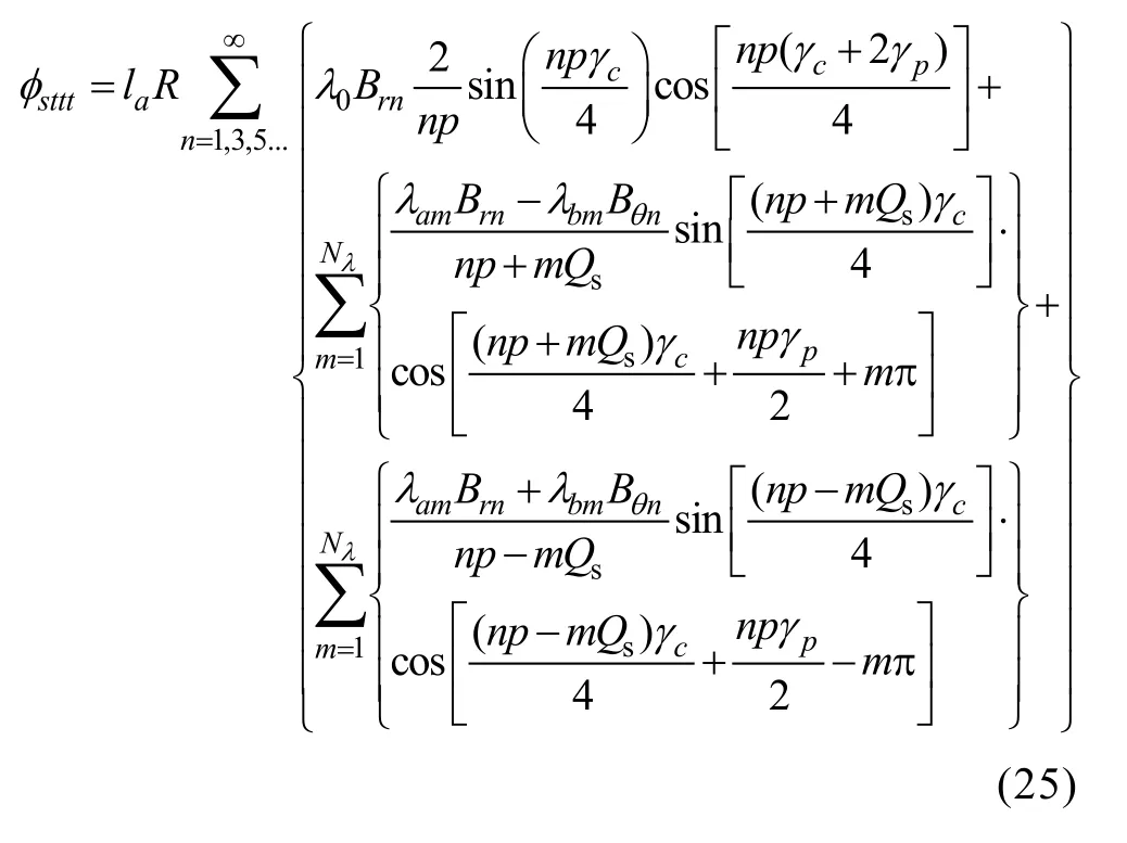
As the tangential flux density is approximated by an equivalent sinusoidal wave, the iron loss caused by the harmonics cannot be considered which will introduce some errors to the iron loss of the tooth tips.
4 No-load iron loss model
The no-load stator iron loss can be predicted based on the magnetic fields in the teeth, yokes and zigzags.As discussed before, the flux density waveforms of all teeth are the same and there is only a fixed phase shift in time between the adjacent teeth. Therefore, in an electric period, the iron loss generated in each tooth should be the same. Similarly, the iron loss of each yoke or tooth tip is also same.
In this paper, it is assumed that there is only radial magnetic field in the tooth and tangential magnetic field in the yoke. Therefore, the iron loss of teeth and yokes can both be calculated by the Bertotti model. Because there is rotating magnetic field in the tooth tip, the iron loss of tooth tips should be calculated by the orthogonal decomposition model.
According to the Berttoti model, the iron losspFein watts per volumeis usually divided into three components:hysteresis lossph, classical eddy current losspcand excess losspe.
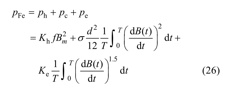
whereKhis the coefficient of the hysteresis loss,Kexcis the coefficient of the excess loss, they can be obtained by fitting the loss data of the core material provided by manufacturers. The coefficient of the eddy current loss can be determined by both the electric conductivity of the laminationsσand the lamination thicknessd.
It is assumed that the magnetic flux densityB(t) in iron core is ideal sinusoidal distribution with time. The amplitude of the sine wave isBm, then in an electric period, (26) can be simplified as follows.

(27) just takes into account the iron loss caused by the fundamental magnetic field. To calculate more accurately, the iron loss caused by the harmonics also should be considered. The conventional method is to use Discrete Fourier Transform to analyze the time-varying magnetic flux density waveforms obtained by the FEM in frequency domain[11]. In this paper, as expressed in(18) and (21), the harmonics of the magnetic field in stator core can be obtained analytically. Based on the amplitude of each harmonic, the iron loss density (W/kg)of the teeth and yokes are derived respectively.

According to orthogonal decomposition model, the iron loss of the tooth tips consists of radial and tangential components. The iron loss density of the tooth tips can then be calculated.

wherePsttris the same asPst. The tangential component takes into account only the iron loss caused by the fundamental magnetic field.

The segmentation of the stator region is shown in Fig.3. It is based on the distribution of the magnetic lines of force at the two moments shown in Fig.4.
The dotted line in Fig.4(a) is designed to be the boundary between the tooth and the yoke, and the dotted line in Fig.4(b) is considered to be the boundary between the tooth and the tooth tip.
The magnetic field at the junction of the tooth and yoke is also the rotating magnetic field. As there is no effective analytical method to predict it, in this paper,the iron loss of this region is replaced by both the iron loss of the corresponding tooth and yoke. That will also introduce some errors to the calculation of the iron loss.

Fig.3 Stator region segmentation
5 FEA verification
A FEM of a 20-pole/24-slot PM synchronous motor is used to verify the validity of the AM of the no-load iron loss. As shown in Fig.5, the motor has the fractional-slot concentrated windings and the surfacemounted poles. The main parameters of the motor are shown in Table 1. The distribution of the magnetic flux density of FEM is shown in Fig.6.
5.1 Iron loss measurement

Fig.5 Diagram of 20-pole/24-slot PM synchronous motor
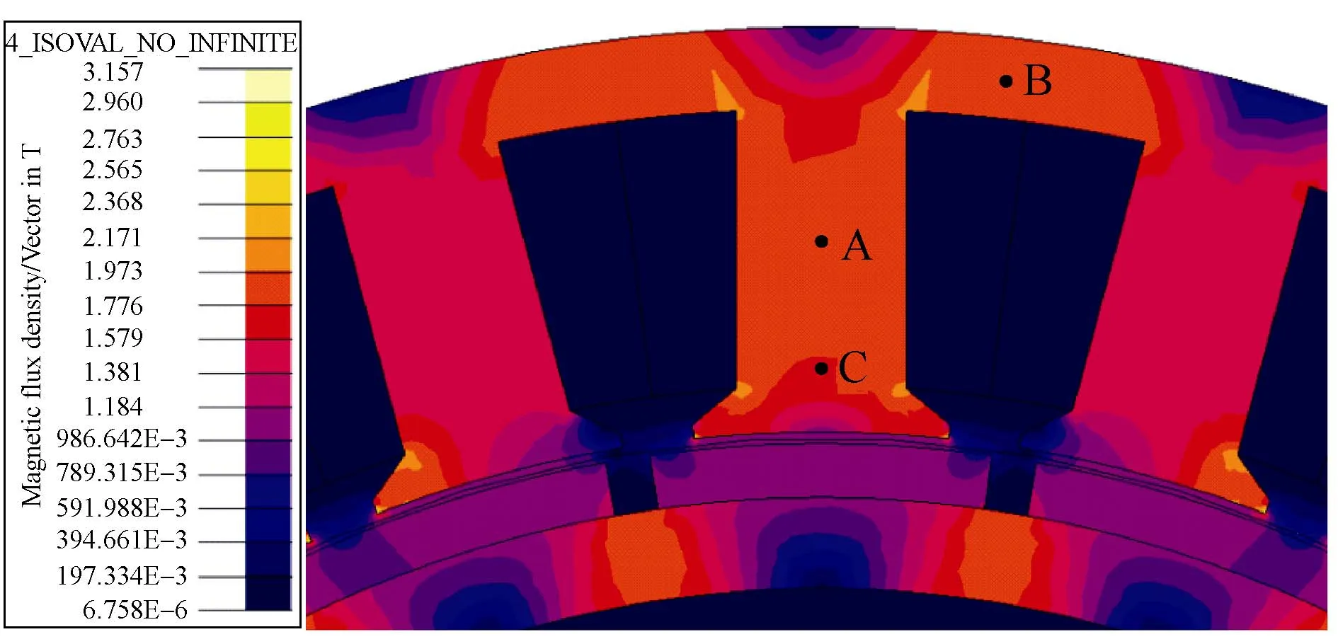
Fig.6 Distribution of the magnetic flux density of FEM

Table 1 Main parameters of the motor
To improve the power density, the material named 1J22 is used for the stator core because of the high saturated flux density. To the author’s knowledge, there is less pre-existing datum about 1J22 iron loss[16]. To obtain more accurate data of 1J22 iron loss, a ring specimen shown in Fig.7(a) is made. Primary winding and secondary winding are wound around the inner and outer layer of the specimen respectively. A sinusoidal alternating current is fed into the primary winding, and an electromotive force is induced in the secondary winding. The iron loss of the specimen can be calculated by measuring the current and voltage.
As shown in Fig.8, the curves of iron loss with magnetic flux density under alternating magnetic field with different frequencies are measured. The Berttoti model is used to fit the curves and the iron loss coefficients are obtained as shown in Tab.2. It can be observed that the hysteresis loss coefficient and the excess loss coefficient both decrease with the increase of the frequency.
The electrical resistivity of 1J22 is 27μΩ·cm and the thickness of lamination is 0.35mm. Therefore, the eddy current loss coefficient is 0.75 and not changed with frequency.
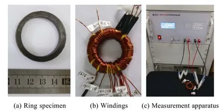
Fig.7 1J22 iron loss measurement
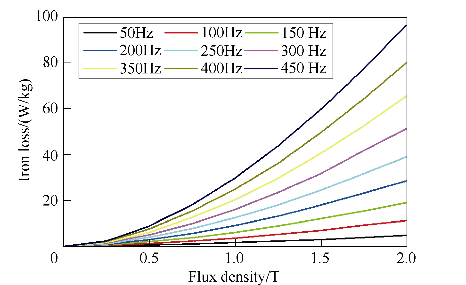
Fig.8 1J22 iron loss curves

Table 2 1J22 iron loss coefficients
5.2 Magnetic field verification
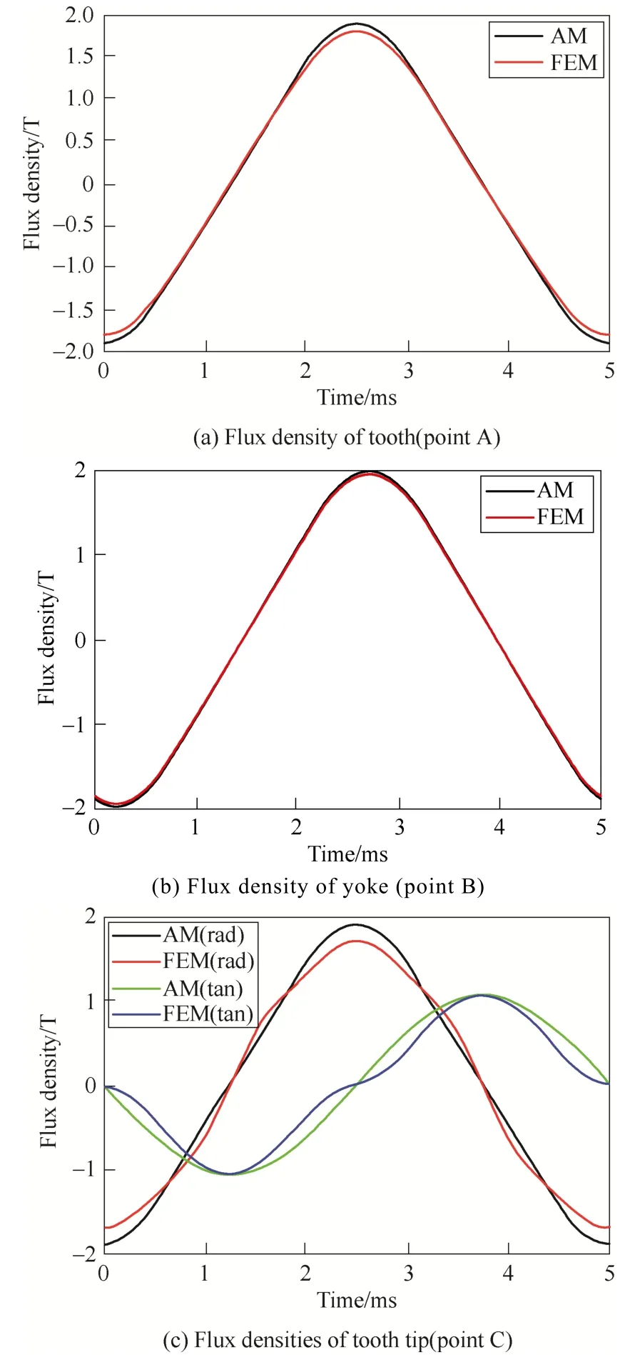
Fig.9 Comparations between AM and FEM
To verify the validity of the analytical magnetic fields in different stator regions, the flux densities of A,B and C points shown in Fig.6 which represent the tooth, yoke and tooth tip respectively are obtained by simulating. The comparisons between the analytical model(AM) and the FEM are shown in Fig.9. The analytical waveform of the tooth is little higher than the FEM one, which is due to the disregard of the slot leakage in the AM. While the analytical waveform of yoke is in good agreement with the FEM one and not higher, because the AM assumes that the maximum yoke flux is half of the maximum tooth flux, when in fact, the proportion should be larger. Overall, the analytical results of the tooth and yoke both have high correlation to the FEM. However, because of the irregular shape of the tooth tip, the magnetic field in tooth tip is more complicated with many harmonics which are not predicted well in the AM, there is a certain deviation between the AM and FEM.
A Fourier analysis of the flux densities of the AM and the FEM are presented in Table 3. It is observed that the harmonic contents of the flux densities of the tooth and yoke are relatively small. The highest harmonics(3rd) account for only 3.69% of the tooth fundamental wave and 5.14% of the yoke fundamental wave in the FEM. While the harmonic contents of the tooth tip are larger, especially the third and fifth harmonics of the tangential flux density account for 17.01% and 3.27%respectively.
5.3 Iron loss verification
As shown in Fig.10, with the motor speed increasing from 300r/min to 2700rpm, the curve of the iron loss with frequency is obtained. It is observed that the analytical results match well with the FEM one. At 2700r/min, the error associated with the FEM results is 5.46%, which is acceptable for the analytical calculation of iron loss.
To further verify the suitability of the proposed model for different dimensions of the motor, in the case of ensuring that the magnetic fields in the iron core are not saturated, the variation of iron loss with the polar arc coefficients, tooth widths and yoke thickness is explored respectively.
Fig.11 shows the variation of iron loss with the polar arc coefficient. It is observed that the iron loss begins to increase linearly with the polar arc coefficient,when the polar arc coefficient is larger than 0.75, the increase rate gradually decreases. The analytical results predict this trend well and are basically consistent with the FEM results.

Table 3 Harmonic contents of the FEM flux densities
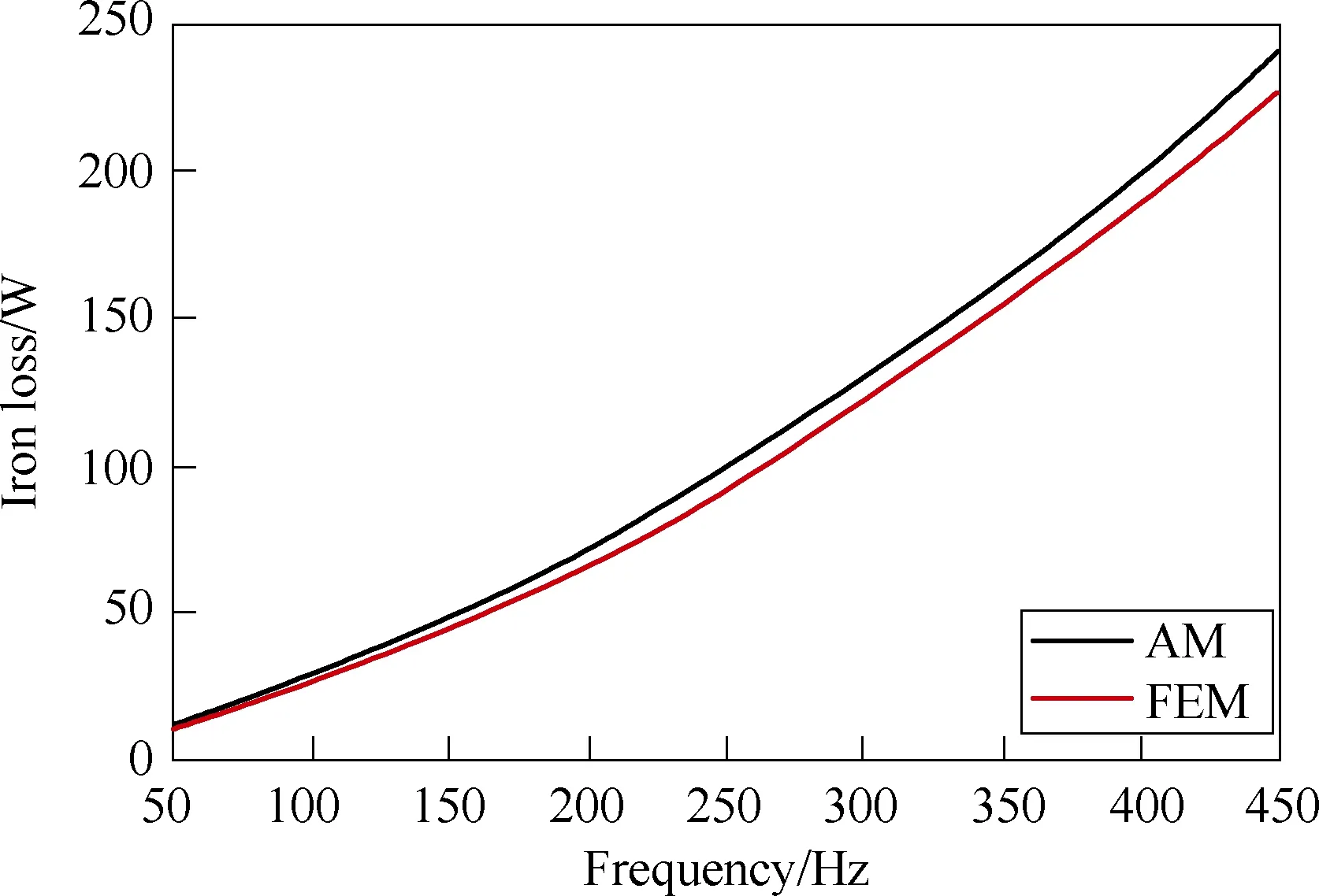
Fig.10 Iron loss with frequency

Fig.11 Iron loss with pole arc coefficient
With the dimensions of the rotor, stator yoke kept constant, the curve of the iron loss with the tooth width is obtained as shown in Fig.12. Although the stator tooth width increases and the volume becomes larger, the flux density of the tooth decreases. Therefore, the whole iron loss decreases with the increase of the tooth width. The analytical results are in agreement with the FEM trend and are a little larger than the FEM values.
With the dimensions of the rotor, stator tooth kept constant, the curve of the iron loss with the yoke thickness is obtained as shown in Fig.13. Similar to the trend of the tooth width, the whole loss decreases with the increase of the yoke thickness. The analytical results are also in agreement with the FEM trend and are a little larger than the FEM values.
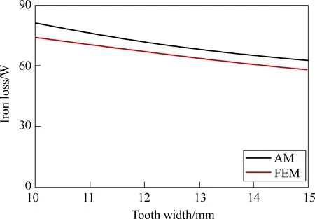
Fig.12 Iron loss with tooth width
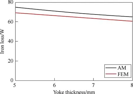
Fig.13 Iron loss with yoke thickness
6 Conclusion
This paper proposes an analytical method for the prediction of no-load iron loss in a fractional-slot surfacemounted permanent magnet motor. According to different states of the magnetic fields, the stator core is divided into three regions, i.e., tooth, yoke, and tooth tip.
According to the existing analytical model of the magnetic field distribution in the slotted air gap, the flux densities considering the harmonics in the stator tooth and yoke are both derived based on the continuity of magnetic flux. Due to the irregular shape of the tooth tip,the tangential flux density of the tooth tip is approximated by an equivalent sine wave and the radial component is regarded to be the same as that of the corresponding tooth.
The Bertotti model is used to calculate the iron loss of teeth and yokes, and the orthogonal decomposition model is used to calculate the iron loss of tooth tips. To obtain the accurate iron loss coefficients, a ring specimen made of the material 1J22 is measured to obtain the iron loss under alternating magnetic field with different frequencies.
An FEM of a 20-pole/24-slot PM synchronous motor is established. The magnetic flux densities of the tooth and yoke match well with those of FEM, and there is a deviation of the tooth tip flux density because of the complicated harmonics. The variation of iron loss with frequency and dimensions, i.e., pole arc coefficient,tooth width and yoke thickness are also consistent with those of FEM, which confirms the validity of the proposed model.
 Chinese Journal of Electrical Engineering2018年4期
- Chinese Journal of Electrical Engineering的其它文章
- Research on Clustering Equivalent Modeling of Large-Scale Photovoltaic Power Plants
- Microgrid Relay Protection Scheme Based on Harmonic Footprint of Short-Circuit Fault
- Study of Pressure Balance for Press-Pack IGBTs and Its Influence on Temperature Distribution
- Field-Oriented Control and Direct Torque Control for a Five-Phase Fault-Tolerant Flux-Switching Permanent-Magnet Motor
- The Characteristics Analysis and Cogging Torque Optimization of a Surface-Interior Permanent Magnet Synchronous Motor
- Resonance Active Damping and PCC Voltage Quality Improvement of DFIG System Connected to Parallel Compensated Grid
