Reliability Analysis of Grid-Interfaced Filter Capacitors
(Department of Energy Technology, Aalborg University, Aalborg, 9220, Denmark)
Abstract: Growing with the increased adoption of renewable energy for the power generation, the reliable and cost-effective operation of grid-connected inverters is of more and more importance. A filter is interfaced between an inverter and the utility grid to reduce the switching harmonics. According to the modulation scheme and the LCL filter impedance, the electrical stresses of the filter capacitor can be thoroughly investigated. With the help of the electro-thermal model, its long-term thermal stress can be obtained based on the mission profile like wind speed, ambient temperature. The reliability of the filter capacitor bank is obtained based on its individual capacitor reliability curves and reliability block diagram method. A case study on a 2MW wind turbine system demonstrates the relationship between the lifetime of the capacitor bank and the single capacitor. Moreover, the severe voltage and current stresses of the filter capacitors are analyzed during abnormal operations (e.g., fault ride-through) with asymmetrical parasitic parameters.
Keywords: Metalized polypropylene film capacitor, reliability, doubly-fed induction generator, fault ride-through.
1 Introduction
With the increased adoption of renewable energy for the power generation, the three-phase voltage source inverter has become an important interface to convert clean energy to the utility grid[1]. A filter is usually required in between to introduce a current feedback control. A single inductor L filter can be used, but the harmonic attenuation may not be sufficient. A high voltage drop is produced due to the bulky inductor.Especially in the high-power application, where the switching frequency is always limited by the associated switching losses, such a simple configuration may lead to the costly passive filter and slow down the system dynamic response[2]Commonly, a high-order LCL filter is used, as it achieves a higher attenuation along with the weight saving of the components. The smaller inductor and capacitor used in the LCL filter minimizes the amount of current harmonics injected into the utility grid,which complies with the harmonic standards.
The performance of capacitors is highly affected by its operational conditions such as the voltage, current,frequency, and temperature. Many researchers have investigated the degradation of the electrolytic capacitors[3-7]. For instance, a real-time failure detection method is developed by estimating the changes in its Equivalent Series Resistance(ESR) and capacitance[5].Lifetime prediction models of electrolytic capacitors are established for the switch-mode power supplies and variable-frequency drivers[6-7]. However, few studies investigate the reliability analysis of the film capacitor considering mission profile[8], and this paper develops the approach to evaluate the reliability of the capacitors in the grid-interfaced filter. Moreover, it is a physicsof-failure approach[9]from the component-level to system-level reliability that based on electro-thermal modeling, lifetime modeling, Weibull analysis, and reliability block diagram.
The structure of this paper is organized as follows:Section 2 describes the design criteria and failure mechanism of the filter capacitor. Electrical stresses of the filter capacitor are presented in Section 3. According to the mission profile based lifetime prediction of the individual capacitor. Section 4 presents the time-tofailure of individual capacitors and the lifetime of the filter capacitor bank. Section 5 evaluates impact of asymmetric parasitic parameters on the filter capacitor stress under grid faults. The concluding remarks are drawn in the last section.
2 Design criteria and failure mode of filter capacitor
As shown in Fig.1, the grid-connected inverter is widely used in renewable energy systems. Due to the switching harmonic introduced by the Pulse Width Modulation(PWM) inverter, a filter is usually applied in between to limit the corresponding harmonic current flowing into the grid[10].
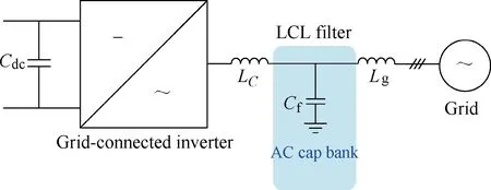
Fig.1 Configuration of a grid-connected inverter with an LCL filter
As the LCL filter features as higher impedance at switching-frequency range compared to the single L filter, it is a preferred solution used in the grid-connected inverter. The design procedure of the LCL filter is described in [11], the inverter-side inductor is selected according to the current switching ripple requirement,while the grid-side inductor is chosen on the basis of the harmonic specification from the IEEE standard. For the filter capacitor, it is designed as seen from the additional introduced reactive power. As larger capacitance causes higher current stress of the power component and higher loss dissipation, 5%~10% of the absorbed reactive power at the rated operation condition is the rule- of-thumb[11].
It is well known that various types of capacitors are used in power electronic converters. Electrolytic capacitors are applied in the case of the high capacitance per volume(e.g. DC-link applications). Due to the polarity, the film capacitors are used in the grid filter owing to the high electric-field stress. Moreover, the material of polypropylene is preferred as compared to polyethylene terephthalate, because of the much lower loss factor. One of the main failure modes is caused by the high capacitor temperature and high current, which leads to a reduced breakdown voltage and even melting of the capacitor.
3 Capacitor performance under normal grid condition
Based on the modulation scheme of the power converter, this section starts to analyze electrical stresses(e.g. the ripple current, and voltage) of the filter capacitor with the help of the LCL filter impedance modeling. In the case of a Doubly-Fed Induction Generator(DFIG) based wind power generation, the impact of loading conditions on capacitor electrical stresses is investigated and evaluated.
3.1 Electrical stresses of filter capacitor
In order to evaluate the current flowing through the filter capacitor, it starts with the analysis of the converter voltage. According to the impedance characteristics of the LCL filter, both the converter-side current and the grid-side current are analyzed, and the capacitor current is also calculated.
For the three-phase system, the space vector modulation(SVM) is preferred compared to the Sinusoidal Pulse Width Modulation(SPWM) due to its higher DC-link voltage utilization. The duty cycle of the two adjacent non-zero vectors (d1,d2) and the zero vectors (d0) can be obtained at different sectors,
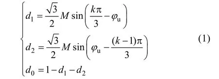
wherekdenotes the sector number;Mdenotes the modulation index (0≤M≤1.15), which equals to the inverter peak voltage over a half of the DC-link voltageVdc;φudenotes the phase angle of the inverter voltage.
As shown in Fig.2(a), six sectors (Sector 1 to 6) can be divided in accordance with the phase angle of the inverter voltageφu. In the case of Sector 1, the voltage vectorVois composed of two adjacent active vectorsV1(100) andV2(110) (with duration periods ofT1andT2within the switching periodTs), as well as two zero vectorsV0(000) andV7(111) (with duration period ofT0within the switching periodTs). Both the active and zero vectors are symmetrically arranged in order to achieve the minimum harmonics of the output voltage[12]. The possible switching patterns of the power devices are described in Fig.2(b) in details. Due to the symmetrical loading of the three-phase system, the inverter voltageVaois illustrated in Fig.2(c). Depending on the various switching states of the power devices, it can be seen that the output voltage includes the levels of 2Vdc/3,Vdc/3,and 0. By using the similar approach, the inverter voltage waveform can be obtained in the other five sectors, which contains three voltage levels within the same sector as described in Fig.2(d).
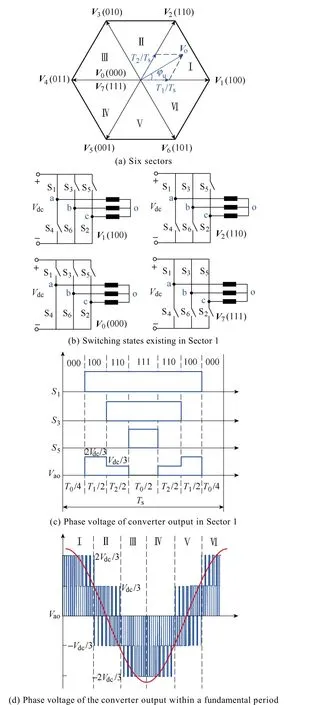
Fig.2 Illustration of space vector modulation
In order to obtain the fundamental and harmonic components of the converter voltage, the Fourier analysis is employed. Based on the impedance characteristics of the LCL filter, the electrical stresses of the filter capacitor are calculated. For a pulse voltage, its Fourier coefficient is calculated by its starting and ending time instants together with its voltage amplitude[12]. Since 7 pulse voltages exist within a switching period, the Fourier coefficient is summed up together with the duty cycle and its corresponding voltage amplitude. With the voltage amplitude distribution in various sectors, the Fourier coefficient can be further accumulated from a single switching period to the whole fundamental period. Thereafter, the fundamental and harmonic components of the converter voltage can be deduced.
Since the majority of the converter fundamental current flows into the power grid, the branch of the filter capacitor can be regarded as an open circuit as shown in Fig.3(a). Under the super-synchronous and sub-synchronous operation modes, the grid-connected converter generates and absorbs the active power,respectively. The vector diagram between the converter voltage and grid voltage can be found with the voltage drop across the filter inductor. As the result, the voltage across the filter capacitor can be obtained as well as the capacitor current.
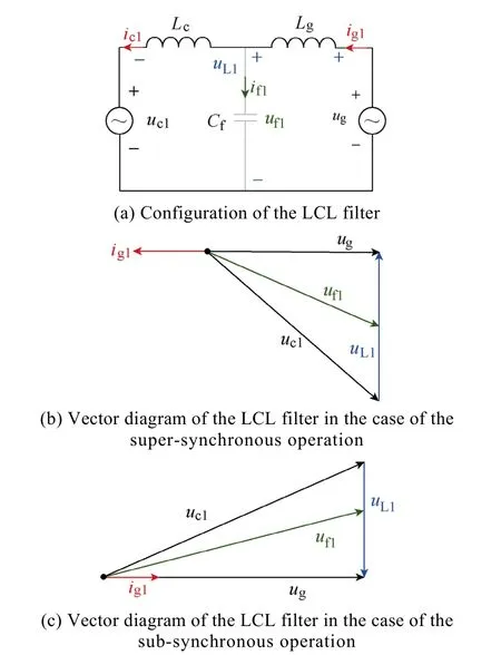
Fig.3 Relationship between the converter voltage and the filter capacitor electrical stresses
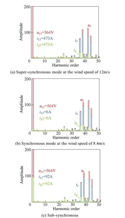
Fig.4 Converter voltage, converter-side current and grid-side current FFT analysis of the grid-connected converter
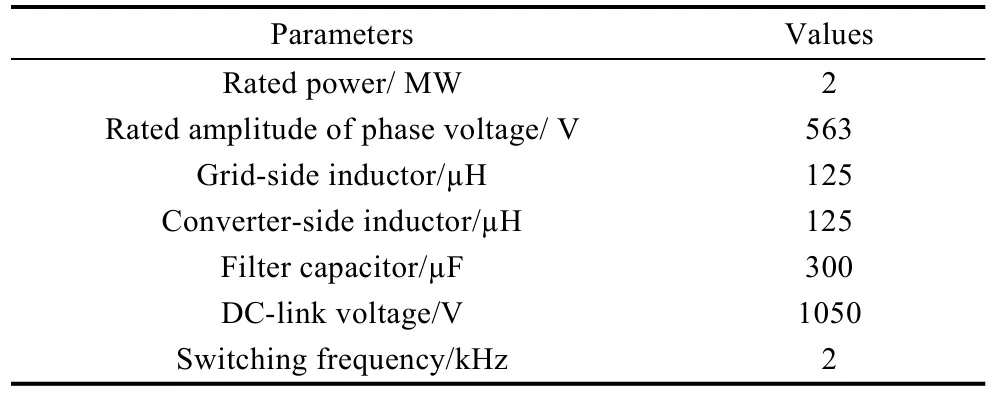
Table 1 Parameters of A 2MW DFIG system
As described in [13], the modulation index and the phase angle of the converter voltage can be deduced based on the converter modeling represented in the dq-reference frame. The FFT analysis of the converter voltage is shown in Fig.4, where the wind speeds of 12m/s, 8.4m/s, and 5.9m/s represent the supersynchronous, synchronous, and sub-synchronous operation of the DFIG. It can be observed that,regardless of the operational modes, the fundamental voltage is always 564V, which is similar to the grid voltage due to the negligible voltage drop across the LCL filter. However, the fundamental component of the converter-side current changes considerably at various wind speeds, which becomes the lowest at the synchronous mode due to little active power flowing through the back-to-back power converter. As the LCL filter generally behaves as a low-pass filter, the fundamental component of the grid-side current is the same as the converter-side current.
It is well known that the RMS of the voltage or current is defined as the square root of the mean square,which consists of both the fundamental component and harmonic components. In addition, as the output power of the wind turbine obeys the maximum power point tracking(MPPT) algorithm[13-14], the relationship between the converter voltage and the wind speed can be established. Based on the FFT analysis of the converter voltage and current, their fundamental, harmonics and RMS values can be obtained as shown in Fig.5 from the cut-in wind speed(4m/s) until the rated wind speed(12m/s).
3.2 Simulation validation
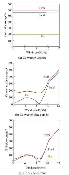
Fig.5 Analysis of the fundamental, harmonic and RMS components

Fig.6 Simulation results of the grid-connected converter at the wind speed of 12m/s in time and frequency domain
With the harmonic spectrum of the converter-side current and grid-side current, their total harmonic distortions(THDs) can be obtained. As the harmonic component of the capacitor current is dependent on both its amplitude and phase angle, the worst case THD can be roughly estimated by the sum of the converter-side current and the grid-side current[15]. The simulation results of the grid-connected converter are shown in Fig.6, where the harmonic spectrum of the converter voltage, converter-side current, grid-side current, and the filter capacitor current is investigated. For the converter voltage, its fundamental component and dominant harmonics are consistent with the theoretical calculations as shown in Fig.4(a). Moreover, the fundamental component of the converter-side current and grid-side current is almost the same, and the switching harmonics of the grid-side current are considerably reduced compared with the converter-side converter current. In respect to the capacitor current, it mainly contains the switching harmonics, while the fundamental current is significantly reduced.
Under different loading conditions, the calculated and simulated THDs are summarized and compared in Fig.7. At the wind speed of 12m/s, the calculated fundamental component of the converter-side current and the grid-side current is 1.0pu with their THDs of 34% and 8%, respectively. Moreover, it can be seen that the fundamental component of both the simulated converter-side current and the grid-side current is 0.97pu,and their THDs are 36% and 10%. For the capacitor current, the calculated and the simulated THDs are 43%and 44%, which agree well with each other. At the wind speed of 5.9m/s, it is evident that the fundamental component is considerably reduced due to the lower produced power, while the THD is significantly increased because of the similar harmonic components.
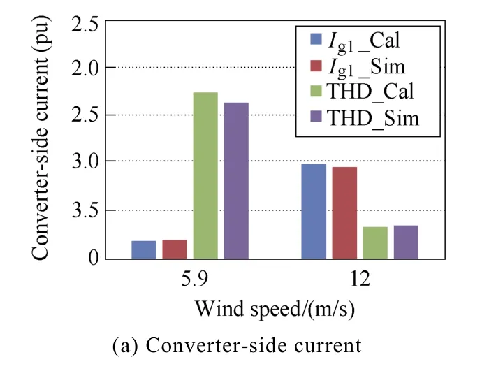
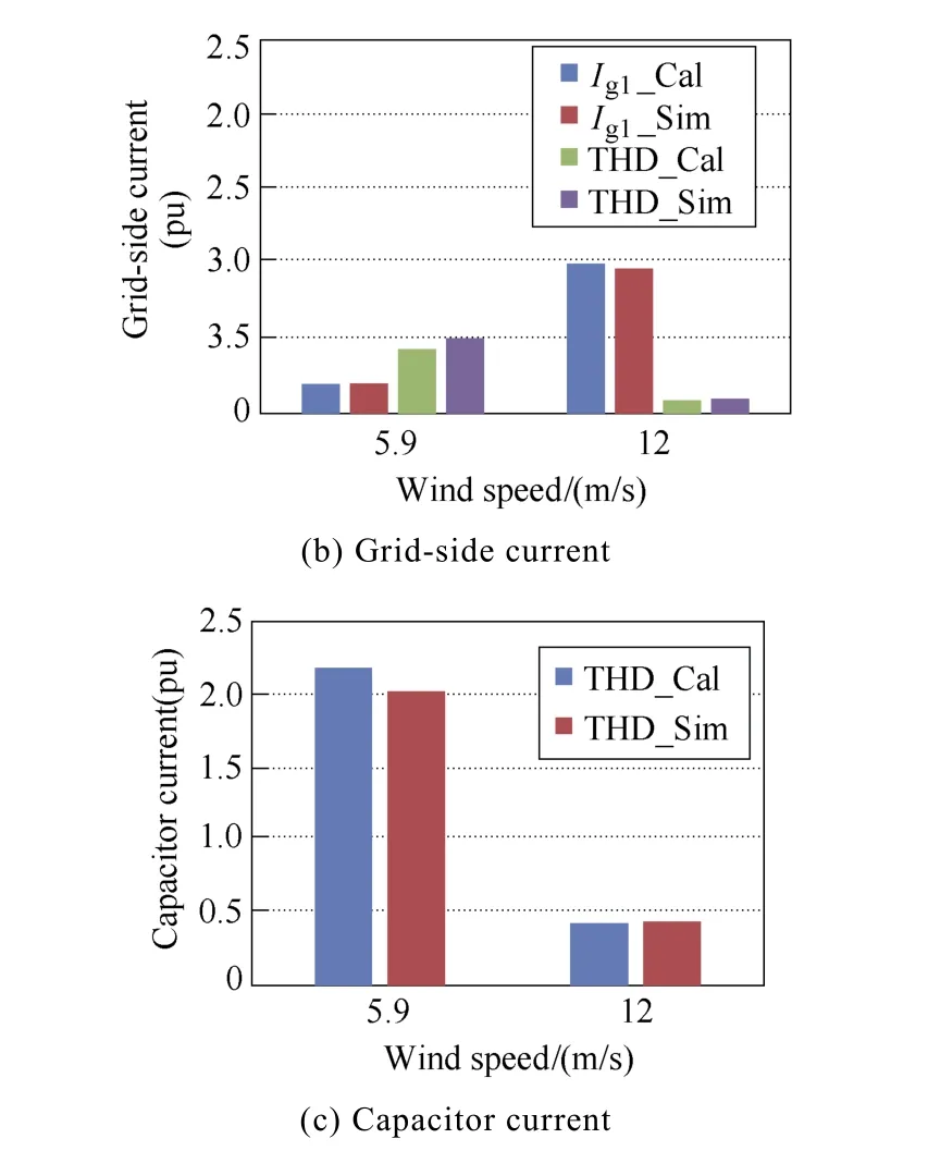
Fig.7 Harmonic comparison between the calculation(Cal)and simulation(Sim) of filter capacitor current
4 Reliability analysis from individual capacitor to capacitor bank
With the information of the lifetime model, the percentile lifetime of the individual capacitor can be converted into its corresponding time-to-failure. Then,the reliability evaluation of the capacitor bank can be analyzed by using the reliability block diagram.
4.1 Capacitor lifetime model
Due to its bipolar operation and ripple current capability, the film capacitor is usually selected to mitigate the PWM harmonics. As the polypropylene loss becomes the main failure mechanism, the rated lifetime of a typical film capacitor is no less than 100,000 hours at 75℃ and dry condition. Moreover, the film capacitor is sensitive to the applied voltage, where the lifetime decreases with an increasing applied voltage. The relationship between the operational hour and the capacitor core temperature as well as the applied voltage is expressed as

whereLxdenotes the hours to failure used in the real application, whileLrdenotes the hours to the failure of the rated voltageVr, and upper category temperatureTr.The second and third components denote the impact from the core temperatureTc, and the applied voltageVx.The detailed parameters for the lifetime model are listed in [16], which is graphically shown in Fig.8.
4.2 Mission profile based capacitor lifetime
According to the mission profile of the wind turbine system (e.g. wind speed and ambient temperature), a general procedure to calculate the lifetime of the film capacitor is shown in Fig.9. On the basis of the wind speed, the produced power is predicted by the MPPT curve, and the current and voltage stresses of each capacitor are evaluated with the generator and converter models. By distinguishing the fundamental and switching components of the filter capacitor current,the core temperature of the capacitor can be jointly decided by the core-ambient thermal resistance and the ambient temperature. Together with the applied voltage across the filter capacitor, the lifetime of the individual capacitor is estimated.
With the annual wind speed (Class I) and ambient temperature with the sample rate of 1 hour as shown in Fig.10(a), the ripple current and the annual accumulated damage are shown in Fig.10(b), (c), respectively. It can be seen that the annual damage increases linearly due to the smooth ripple current throughout the year.

Fig.8 Hour to failure of metalized polypropylene film capacitor with respect to various operating temperatures and applied voltage

Fig.9 Flowchart to calculate capacitor lifetime from mission profile
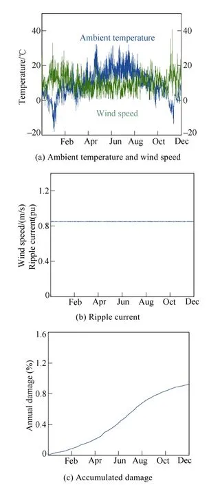
Fig.10 Annual profile comparison between the metalized polypropylene film capacitor (MPF-CAP) and the aluminum electrolytic capacitor (Al-CAP)
4.3 Reliability evaluation of the capacitor ban k
Considering the tolerance and parameter variation,theB10lifetime of the individual capacitor is converted into its reliability curve along with operation hours.Then, the reliability of the capacitor bank is evaluated with the help of the reliability block diagram.
In order to fulfill the required capacitance and withstand the voltage stress, several capacitors are connected in parallel as a capacitor bank. The detailed structure of the filter capacitor bank is shown in Fig.11(a). Since any failure of the individual capacitor may result in the degraded performance of the capacitor bank, all of the capacitors are connected in series in the reliability block diagram as shown in Fig.11(b).
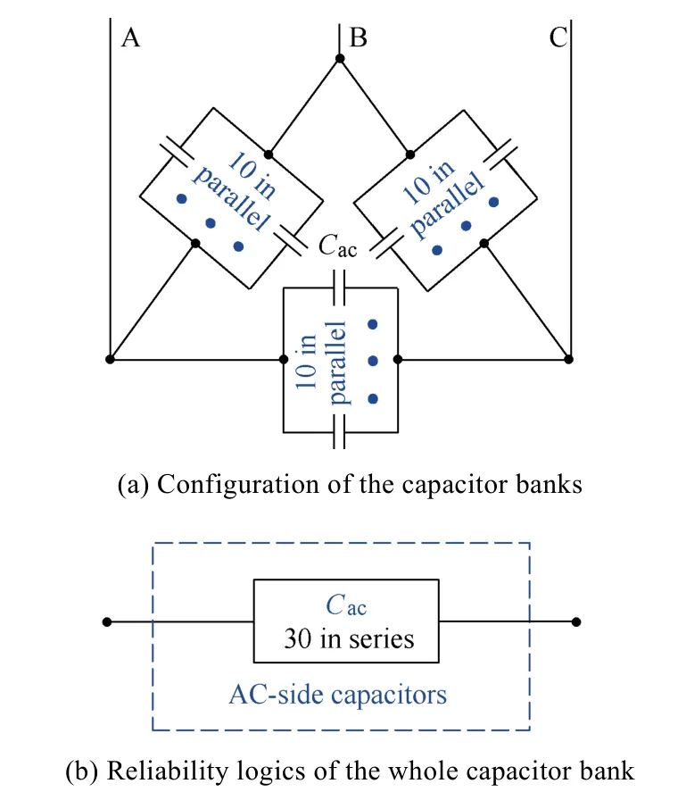
Fig.11 Capacitor banks and its reliability
In order to assess the reliability performance for the capacitor bank, theB10lifetime of the individual capacitor is insufficient, and its time-to-failure distribution, which considers the parameter variations and tolerance uncertainties of the capacitor samples,it is required in order to apply the reliability block calculation. Since the Weibull shape parameter is identical in the case of the same failure mode[8], and the whole unreliability curve along with the operational hour can be obtained as shown in Fig.12. Moreover, the unreliability curve of the capacitor bank can be deduced from the individual capacitor. Seen from the 15-year designed lifetime of the capacitor bank, the damage of the individual film capacitor becomes 0.0005%, while the capacitor bank damage significantly increases to 0.015%. It is evident that the lifetime relationship between the single capacitor and the capacitor bank is obtained quantitatively. As a large amount of the capacitor cells are applied to form the capacitor bank,the reliability issue of the capacitor bank could become more critical, which results in the optimized capacitor bank design seen from the reliability point of view.
5 Impact of grid fault on filter capacitor stresses
A grid voltage sag is a short duration with the reduced RMS voltage, which can be caused by a short circuit, overload or starting of electric motors. Therefore,the LVRT (Low Voltage Ride Through – also known as FRT-Fault Ride Through) has become a crucial feature of the wind turbine control system. Different LVRT requirements of the stay-connected time duration are defined in Fig.13[17-18].

Fig.12 Unreliability curve from the single capacitor to the capacitor bank
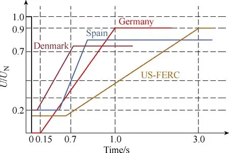
Fig.13 LVRT requirements of wind power systems in different countries
During the LVRT operation, the grid-side components,such as three-phase filtering capacitors, are more severely stressed with voltage and current, which could raise the failure rate of the grid-side passive components.More severely, the asymmetric three-phase capacitor parameters (e.g., capacitance, parasitic inductance) may introduce circulating current in the three-phase capacitor bank, which increases the capacitor hot-spot temperature and accelerates the degradation or catastrophically fail the capacitors. Therefore, the investigation of the electrical stresses of three-phase filter capacitors under grid fault operation is necessary.
In order to clearly define the reliability issue, a three-phase filter capacitor in a 2MW DFIG wind turbine application is studied. The filter capacitor bank with delta connections and asymmetrical parameters are used for investigation. The rated RMS voltage is 730V and the rated current is 50A. The capacitance for phaseaandbis 75μF, the ESR is 1.1mΩ and equivalent series inductance(ESL) is 135nH. Different from that, the measured parameters for phasecare 65μF capacitance,2.2mΩ ESR and 220nH ESL. As a comparable study case,the simulation waveforms of the three-phase capacitor voltage and current with the normal operation are shown in Fig.14(a). Both the voltage and current are stable and within the rated value. Different from that, when a voltage drop to zero for 0.15 second is applied at the grid, the capacitor current and voltage are distorted significantly in a short period as shown in Fig.14(b). It can be seen that:① The maximum voltage is more than 2 times of the rated one, which may result in catastrophic failure depending on the duration.; ② The maximum current in this period is more than 7 times of the rated maximum current, which could raise the hot-spot temperature and accelerate the degradation process of the capacitors.
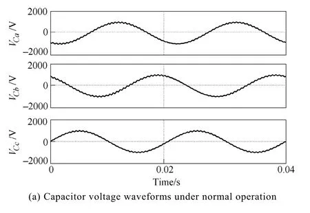

Fig.14 Three-phase filter capacitor waveforms under normal and LVRT operation
6 Conclusion
Aiming for the grid-connected inverter used in the wind power system, a reliability analysis method of the LCL filter capacitor bank is presented in this paper.According to the converter modulation scheme and the LCL filter impedance characteristic, the electrical stresses(e.g. ripple current, voltage) of the filter capacitor are analytically calculated. By doing so, the annual mission profile(e.g., the wind speed, ambient temperature) is translated into the long-term thermal stress of the filter capacitor, which facilitates its percentile lifetime prediction. Considering the parameter variations among capacitors, the Weibull function based time-to-failure distribution of the single capacitor can further be converted into the filter capacitor bank reliability by using the reliability block diagram. A case study on a 2MW wind turbine system demonstrates that lifetime relationship between the single capacitor and the capacitor bank is obtained quantitatively. Moreover,the asymmetrical parasitic parameters impact on the electrical stress of the filter capacitor is also investigated,which illustrates that the transient capacitor current and voltage could become multiple times higher compared to the normal operation.
 Chinese Journal of Electrical Engineering2018年3期
- Chinese Journal of Electrical Engineering的其它文章
- A Comprehensive Survey on Fault Diagnosis and Fault Tolerance of DC-DC Converters
- Active Thermal Control for Delaying Maintenance of Power Electronics Converters
- Capacitive DC Links in Power Electronic Systems-Reliability and Circuit Design
- Study of the Characteristics and Suppression of EMI of Inverter with SiC and Si Devices
- Circuit Implementation of Power Converter for High-Speed Switching Operations
- Design, Implementation and Performance of Synchronous Current Regulators for AC Drives
