Active Thermal Control for Delaying Maintenance of Power Electronics Converters
(Christian-Albrechts-Universität zu Kiel, Kiel, Germany)
Abstract: Several studies have reported about power semiconductors and capacitors being the most sensitive components in power converters. The lifetime of these devices is associated with the mission profile and the resulting temperature profile. For preventing failures, it is of interest to estimate the Remaining Useful Lifetime(RUL) and several condition monitoring methods have been proposed for this purpose. Moreover, modular power converters consist of a high number of components and methods have been proposed to reduce the thermal stress and therefore extend the lifetime of a system with software, referred to as active thermal control. For power converters with limited accessibility, the RUL detected by the condition monitoring system may not fit to the scheduled maintenance of the system and devices may still have a significant RUL when their replacement is scheduled. Therefore,this work proposes to control the stress of the most deteriorated components in the system such that the failure probability of multiple building blocks is equalized when the next maintenance is scheduled.Moreover, this concept is proposed to extend the time to the next maintenance and reduce the number of maintenance instances without affecting the mean lifetime of the system.
Keywords: Power electronics, reliability, condition monitoring, active thermal control, prognostic maintenance.
1 Introduction
Power electronics is consolidated in a wide range of application fields such as variable speed drives,electric vehicles and renewable energy systems. Apart from ongoing improvements in these systems, other applications, like solid state transformers, smart transformers and more electric aircraft are emerging[1].These new applications are bringing new requirements and challenges, such as high reliability and long lifetimes in environments, which may be difficult to access[2].
For ensuring the continuous operation of a system,the design for reliability has been proposed[3]. However,certain applications require lifetimes of several decades and a sizing for such long time periods may not be practical. If a device fails before the system is close to its end of life, maintenance needs to be scheduled and the device needs to be replaced. For power converters,power semiconductors and capacitors have been found to be the devices, which are most prone to failure[4].However, their failure mechanisms are well understood and several condition monitoring techniques have been proposed for these devices[5].
To ensure continuous operation, concepts for fault tolerance of converters have been proposed with redundancy on different levels. Nevertheless, the failure of components may not be predicted and the failures are not coordinated. Consequently, in the worst case different devices fail at similar time instances and the system will be shut down. This is targeted to be prevented with condition monitoring techniques, which predict the RUL[6]. In addition, active thermal control for power electronic modules and capacitor ripple cancellation can be applied to reduce the stress and increase the lifetime of the devices[7-8].
This work proposes to apply condition monitoring for capacitors and power electronics and combine this information with thermal control for RUL equalization and lifetime extension. It is proposed to use these concepts for lifetime control and delaying the maintenance. The concept is introduced for an electric drive and the application of active thermal control. In addition, a sensitivity analysis by means of a Monte Carlo simulation is carried out for validating the effectiveness of the proposed concept in a modular power converter.
In the following section, Condition Monitoring(CM) methods and lifetime models for power semiconductor modules and electrolytic capacitors are presented and assessed. Active methods to increase the reliability of power semiconductors and capacitors are studied in section 3 and the application of this concept for delaying maintenance is introduced in section 4,where two study cases are presented. The work is concluded in section 5.
2 Condition monitoring
The concept of condition monitoring(CM) is applied to assess the current health status of a component in a system[9]. This allows for making a prediction about the reliability for the upcoming time of operation and to detect incipient faults in order to take corrective actions before failures occur. Therefore,condition monitoring enables to schedule maintenance according to the system’s needs instead of determining fixed intervals. In the following, condition monitoring for power electronic modules and for capacitors is introduced and commonly used methods are reviewed.
2.1 Condition monitoring and lifetime estimation of power electronics modules
The health status of power semiconductor modules can be obtained by measurement of suitable parameters. For this purpose, several methods require to sense parameters, which are normally not used in the controller and therefore additional sensors and software are required. One of the potential parameters is the on-state voltagevCE,sat, which can be used to monitor the condition of the bond wires[11]. An increment ofvCE,satby 5% is a criterion to detect the end-of-life. An additional sensor to measure the on-state voltage is needed for this approach. In case of MOSFETs, the on state resistanceRds,oncan be used alternatively. Fig.1 shows exemplary the software implementation of this approach. For laboratory conditions, the left part of Fig.2 is showing an infrared camera used for semiconductor temperature measurement. The infrared camera is used to measure the semiconductor temperature profile of an opened IGBT module during operation(Fig.2a) and the optic fiber sensors are used to monitor the temperature inside and on the capacitor(Fig.2b).
The condition of the bond wires can also be obtained by sensing the short-circuit currentISC. This has been demonstrated for an IGBT module[12], whereby the short-circuit current decreases with higher fatigue of the bond wires, due to higher line resistances. A decrement ofISCby 4% is suggested as the criterion for the end-of-life.

Fig.1 Schematic condition monitoring of power semiconductors with
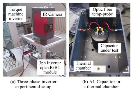
Fig.2 Infrared camera used for semiconductor temperature measurement
The thermal resistances between junction and caseRth,jcand between case and heat-sinkRth,cscan be used to monitor the fatigue of the solder joints[11]. An increment of the thermal resistance by 20% is a criterion to detect the end-of-life. The estimation of the junction temperatureTjis the critical task of this approach.Temperature sensitive electrical parameters(TSEP), such as the on-state voltagevCE,sator the gate threshold voltagevGE,th, can be used to calculateTj. However,additional temperature sensors to measure the case temperatureTcand the heat-sink temperatureTsare needed. Remarkably,vCE,satcan be used for both, the junction temperature estimation and the state of health determination, whereby the separation of these effects remains a challenge.
Furthermore, there are efforts to use the switching time, the gate signals, or system-identification methods to monitor the conditions of different parts of a semiconductor power module[11-13].
As another opportunity the power cycling capability can be used as the lifetime model. Consequently, the state of health of the power semiconductor modules is obtained by temperature sensing. Thereby, the stressor is considered to be the temperature swing and at a certain mean junction temperature as shown in Fig.3. The thermal swing can be extracted from the mission profile using the rainflow counting algorithm[14]and a model links the thermal cycles with the consumed lifetime.Mathematically, the number of cycles to failureNfis described in dependency of the amplitude of thermal cycles ΔTjand the average temperature ΔTj,avgin the Coffin-Manson-Arrhenius model. Its analytical expression is:

Thereby,Eais an activation energy parameter,kis the Boltzmann constant,αandnare experimentally determined constants. An overview on other lifetime models for IGBT modules are given in [15]. The accumulated damage is derived with Miner’s rule and represents the current health status of the semiconductor.
If the cumulative damage obtained by the application of Miner’s rule reaches 1, the component is expected to fail[16]. The main advantage of the method is that it is mainly software based, requiring only the junction temperature measurement as the input.
An assessment of the CM via suitable parameters and of the lifetime model is shown in Table 1.

Fig.3 Block scheme of model-based condition monitoring applied to a power semiconductor module

Table 1 Assessment of CM methods for power semiconductors
2.2 Condition monitoring and lifetime estimation of electrolytic capacitors
Electrolytic capacitors are commonly used in power electronics applications, because of their cost effectiveness. However, they are known to be sensitive to temperature and therefore the system design needs to be considered carefully. Their health status can be obtained by measurement of the capacityCand the equivalent series resistanceRESR[20]. A possible criteria for the detection of the end-of-life are a reduction ofCby 20% or a doubling ofRESR. To determineRESRthe voltage ripple ΔVCand the current ripple ΔiCof the capacitor need to be measured. Fig.4 is showing the bandpass filtering of these measured values for a frequency range, whereRESRis the dominant part of the impedance of the capacitor, and a RMS to DC conversion so thatRESRcan be approximated by (2)[17].

TheRESRcan be determined by using the short-circuit currentISCof an IGBT module[18]. For the determination ofCthe voltage ripple ΔVCand the currentiCof the capacitor have to be measured. The calculation ofCis done by (3).
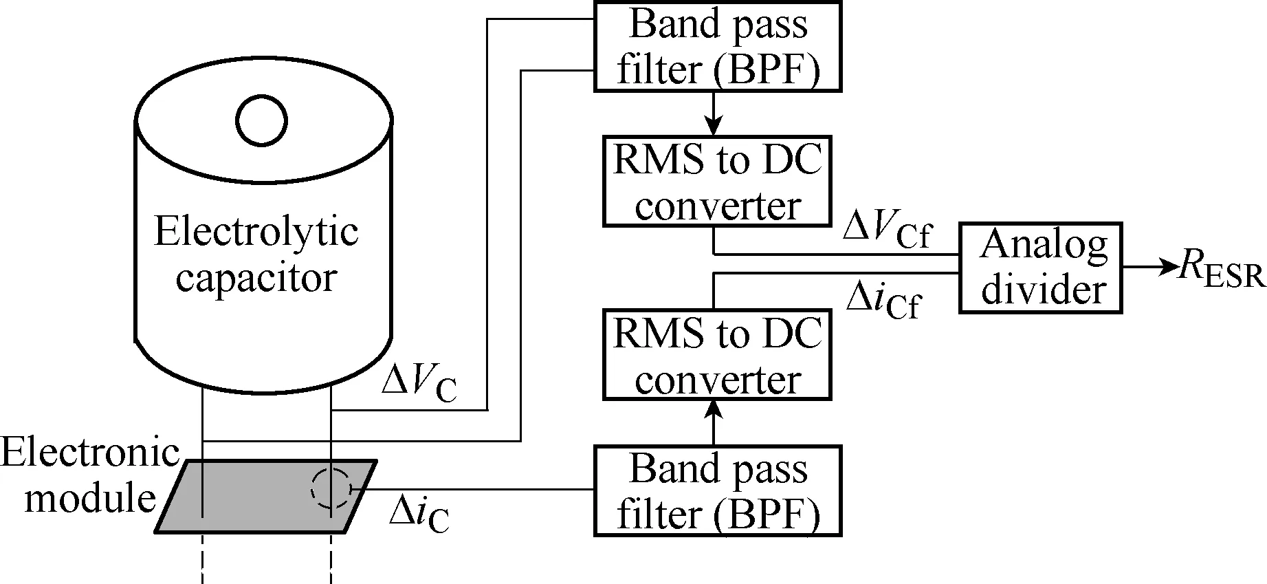
Fig.4 Determination of

Furthermore, the health status of a capacitor can be obtained by a lifetime model. A well accepted lifetime model for electrolytic capacitors is given in [19]. The equation to describe the lifetimeLis:

In this equationTmaxis the maximum permissible temperature,Iais the applied capacitor current,I0is the rated capacitor current, ΔT0is the temperature increase whenI0is applied,Ais the temperature coefficient,Vais the applied voltage,V0is the nominal voltage, andmis a manufacturer dependent voltage factor. The model consists of three parts, where each part considers one of three major stressors: First the impact of the hotspot temperatureThfollows the Arrhenius rule, which constitutes a doubling in lifetime for each 10K temperature decrease. Second is the ripple current which is acting on the temperature rise. Thirdly, the applied voltage is taken into account, as an increasing voltage level causes degradation due to electrolyte evaporation effects[19]. To apply equation (4), the knowledge of the hotspot temperature within the capacitor is the most challenging. A comparison between the different condition monitoring methods is shown in Table 2. As an advanced method for sensing the hotspot temperature of a capacitor, the temperature dependent capacitance can be sensed. A setup for this purpose is shown in the right part of Fig.2, where a temperature sensor with an optic fiber is inserted into the hotspot of the capacitor.The resultant correlation between capacitance and hotspot temperature is shown in Fig.5[21].

Table 2 Assessment of CM methods for capacitors
3 Active thermal control for lifetime manipulation
As a software based opportunity to extend the lifetime of power semiconductors, active thermal control has been proposed to reduce the thermal stress and increase the lifetime. In the following, software based methods are described for capacitors and power semiconductors with the goal to extend the lifetime.
3.1 Active thermal control of power electronic modules
Active thermal control uses temperature related control parameters to influence the junction temperatures of power semiconductor modules online. The goal is to reduce the thermal stress in the module by smoothing the temperature variation. To influence the junction temperatures, the active thermal control increases or decreases the losses in the desired chips temporary. A classification of chosen control parameters by the hierarchic level of interaction with the system is done in Fig.6. The levels reach from system control down to the gate driver. On the layer of the current control a variation of the current limit[23]and control of the loading between parallel converters has been proposed to control the junction temperature[24]. On the layer of the modulator a selection of the switching frequency[25]and the modulation method[26]have been applied. On hardware layer the gate voltage has been adjusted[27].
3.2 Health-based driving using CM
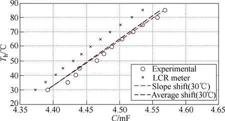
Fig.5 Experimental demonstration of capacitor hotspot temperature estimation on basis of electrical capacitance measurement[22]
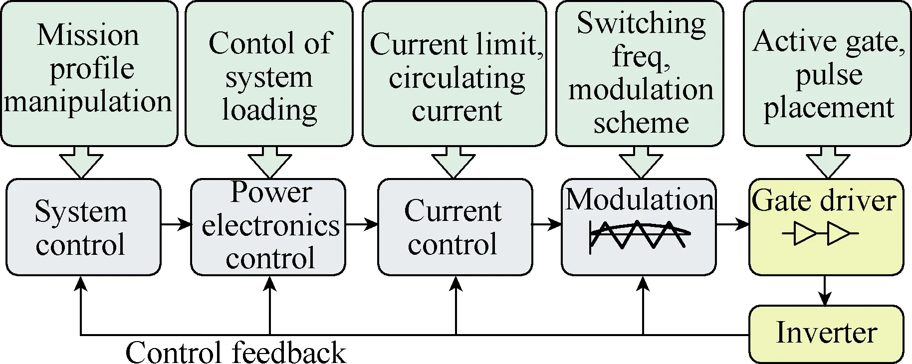
Fig.6 Classification of parameters for Active thermal control by point of interaction with the power electronics control system
The health information given by the condition monitoring can be used for health-based driving of the monitored components. When the first chip in the module fails, the system has to be shut down and the whole module must be replaced. The controller of the health-based driving can release the stress from the most damaged chips in the module. As a consequence the time to failure can be increased and the module durability is consumed more efficient. To realize the health-based driving, the controller must be capable to influence the stress on specific semiconductors in the module. A possibility is to use direct control schemes like the Finite Control Set Model Predictive Control(FCS-MPC) as it is capable to control the conducting of each switch on a module individually[28].
The same concept is applicable for capacitor arrays.However, influencing the stress of single capacitors in a capacitor array implies additional active circuits.
3.3 Active thermal control by means of power routing
Power routing can be used to unevenly load building blocks in modular power converters and thereby control the stress for all devices in one building block[29]. It is proposed to equalize the useful remaining lifetime of the building blocks in a modular power converter. This was proposed for series connected building blocks[19],parallel connected building blocks[24]and building blocks connected by a multi-port transformer[30]. The advantage of the method is the low impact on the efficiency, whereas a disadvantage is that it increases stress for other building blocks in the system.
3.4 Active capacitor voltage ripple reduction
A characteristic of single-phase ac line connected rectifiers is the pulsating power transfer that occurs to the dc bus, which generates a ripple on the dc bus voltage at twice the line frequency when the input voltage and current are sinusoidal[32]. The voltage ripple is usually reduced by usage of dc link capacitors. However, the voltage ripple is a critical stressor on aluminum electrolytic capacitors, metalized polypropylene film capacitors and high capacitance multi-layer ceramic capacitors[33]. Thus, active ripple reduction circuits and voltage compensators have been proposed for increasing the lifetime[34].
4 Thermal control for delaying maintenance
The condition monitoring techniques and active thermal control techniques introduced in the last sections are proposed to extend the lifetime and delaythe maintenance as shown in Fig.7. As can be seen in the figure, condition monitoring is applied to estimate the RUL and active thermal control is applied on the building block level and the system level for delaying and synchronizing the maintenance schedule. In the following one study case for health based drive converter control is shown as well as a Monte Carlo simulation to demonstrate the concept of power routing for maintenance scheduling in a modular power converter.
4.1 Health based thermal control of an electrical drive
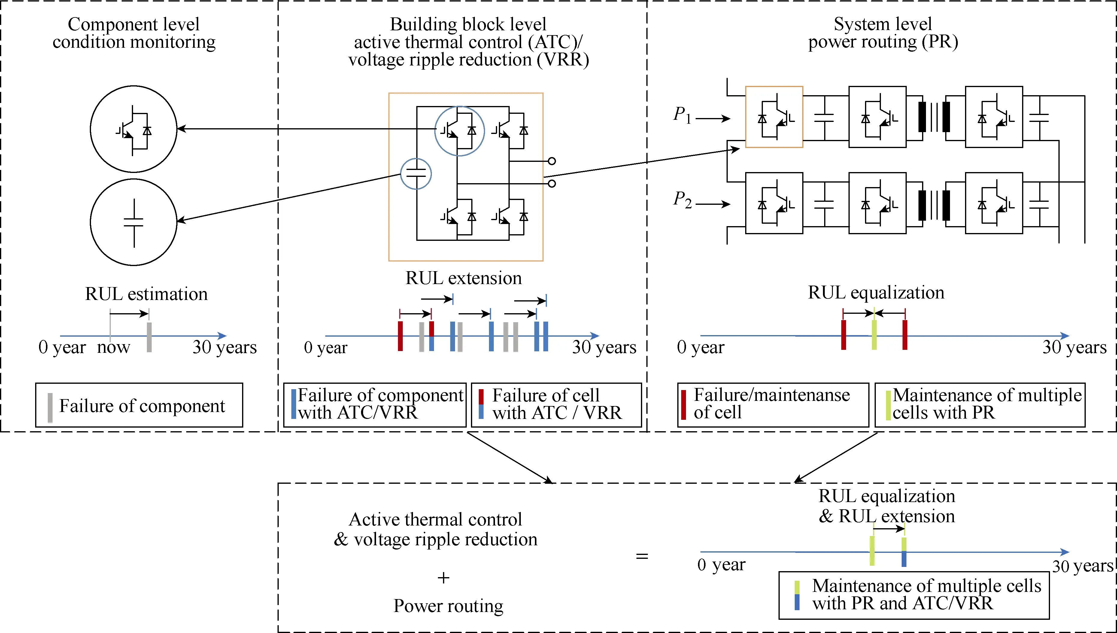
Fig.7 Schematic presentation of the use of condition monitoring, building block based active thermal control,voltage ripple reduction for capacitors, power routing and the combination of the approaches

Fig.8 Active thermal control structure using Finite Control Set Model Predictive Control(FCS-MPC)[31]
As a study case for the demonstration of the concept, a drive consisting of a two level voltage source converter feeding an induction machine is presented.The scheme in Fig.8 shows a junction temperature controller using the Finite Control Set Model Predictive Control(FCS-MPC) to control the amplitude of thermal cycles[28]. The load current, junction temperature and the resulting thermal stress are predicted for all space vectors of the next sampling instant. These predictions are used to derive the FCS-MPC cost function parameters that include the error from the current reference, the thermal stress on the device, the temperature difference between the chips on a power module and the total power losses from switching and conduction the semiconductors. These parameters are weighted and the space vector with the lowest cost function is directly applied to the power converter.
The active thermal control has been implemented to reduce the thermal stress in an IGBT module on a test setup. The mission profile of an industrial process shown in Fig.9 is applied. For comparison the process is also run without the thermal control. A reduction of the thermal cycling amplitude of about 10% to 30%can be observed. The model-based condition monitoring according to Fig.3 has been applied to show the accumulated damage in both cases and thereby, the slope of the accumulated damage over time is reduced to a third of its initial value. The reduction in the damage affects an increase of the remaining useful lifetime.
4.2 Power routing for delaying the maintenance schedule
The second study case discusses the capability of active methods for scheduling maintenances. The idea of maintenance scheduling is illustrated in Fig.7. Using the lifetime models, the RUL of power devices and capacitors are estimated. The ATC methods discussed earlier delays the failure of a single converter cell by reducing the thermal stress of the components. The power routing methods acts on the system level to delay the failures of the cells and thereby reducing the maintenance frequency.
This is demonstrated through study cases of a 3-stage modular Smart Transformer(ST) comprising of a Cascaded H Bridge(CHB) for Medium Voltage AC(MVAC) to MVDC conversion, Dual Active Bridges(DAB) for MVDC to Low Voltage DC(LVDC) conversion. The ST architecture is represented by a graph with edges and nodes as shown in Fig.10 to define the power flow paths.Each CHB cell is connected to a DAB converter cell forming one power flow path from MVAC to LVDC.

Fig.9 Experimental demonstration of the active thermal control and model-based condition monitoring. A mission profile of an industrial process is driven on the machine-connected inverter[31]
In ST applications, the failure of a cell can lead to the lose of a power path and the subsequent maintenance.For the distribution system operator, multiple maintenances of ST result in large system downtime,monetary loss and reduced power handling capability.Therefore, proper maintenance scheduling of ST is important to enhance its potential to compete against the traditional low-frequency transformer.
One of the reasons for the cells in a modular system to fail at different instances is the difference in thermal parameters. For example, even a few degrees difference in the heatsink temperature for the converter cells can result in a considerable difference in the lifetime of the cells. Therefore, even when the cells are sharing the power equally, processed power dependent wearouts are different.
To reduce the maintenance requirements of ST, a power routing algorithm illustrated in Fig.11 is used.In this method, taking advantage of the condition monitoring of each converter cell, the sensed junction temperature is used to calculate the accumulated damage using the scheme described in Fig.3. The mission profile of the ST for the past week generates the junction temperature profile for each converter cell. The junction temperature profile is used to calculate the accumulated damage for the week(ΔD) and the total accumulated damage(D).
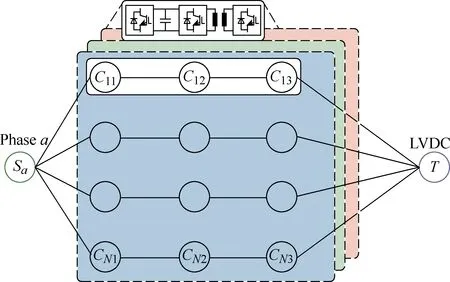
Fig.10 Graph theory representation of CHB DAB based ST

Fig.11 Graphical representation of lifetime control algorithm
The temperature swing variations in the converter cells will result in different expected RUL for each converter cell. In order to adjust the power flow through each cell to obtain equal lifetime, a weight is assigned to each converter to determine the power flow. Depending on the RUL of each converter, the weights are assigned which in turn determines the power flow through them from MVAC to LVDC bus. The weight for each cell is formulated as shown in (5).

Once the weights are determined for each converter cell based on the reliability factors, for each path identified from source to sink, the respective weights are summed up and given to a convex optimization function as given in (6).

The optimization algorithm determines the power referencesfor each converter cell in a path for the entire operating range of the system,P=[0,1]p.u. and are stored in a Look-Up Table (LUT).
To validate the impact of power routing for scheduling the maintenance by RUL equalization, a case study with ST comprising of 10CHB cells connected to 10 DAB cells is performed. The junction temperature of the converter cells for a mission profile is evaluated using the electro-thermal model of the ST[35]. Since the impact of unbalanced power sharing on the aging of CHB cells is minimal, the lifetime impact on CHB cells are not discussed here in detail, but can be obtained from[19].
The Fig.12 shows the progression of accumulated damage over the lifetime of the DAB cells when they share the power equally. The difference in heatsink temperature of about 18℃ results in a failure of the first cell at the 200th month and the last one around the 370th month. For a system with large number of cells, the differences in the cooling of individual cells can result in failure of the cells at different instances while processing equal power, leading to multiple maintenance intervals.
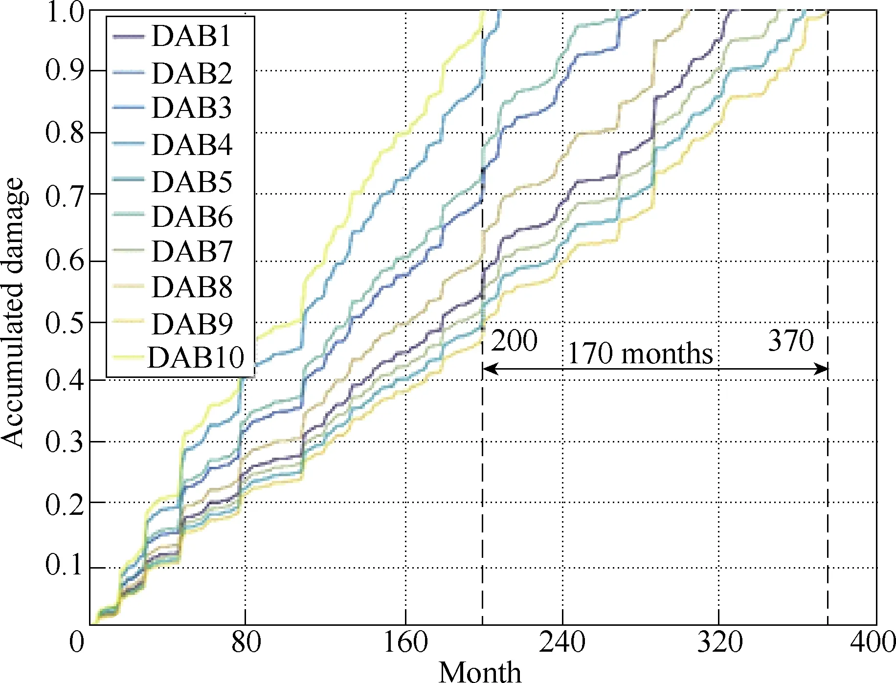
Fig.12 Wearout of different cells of the ST without power routing
To reduce the maintenance intervals, the power routing method converges the accumulated damages of the cells to concentrate the failures around a certain period. The results of the simulation with power routing for the ST is shown in Fig.13. Here, the accumulated damages of all the DAB cells converge around 293rd month and thereby extending the time to the next maintenance cycle.
The sensitivity of the power routing strategy to the differences in heatsink temperatures is studied with a Monte-Carlo simulation, considering the heatsink temperature as a Gaussian distribution with 5% standard deviation, for 1000 cases with 10 cells. The results are shown in Fig.14 and show the distribution of failures over time without and with power routing. The power routing delays the 10% failure probability by 11 months without reducing the system mean life considerably.Moreover, with power routing, the standard deviation of failure probability has reduced to 6 months compared to 15 months under normal operation. This demonstrates the ability of power routing to concentrate the failure probability around the maintenance time.
5 Conclusion

Fig.13 Wearout of different cells of the ST with power routing
The proliferation of power electronics in decentralized and security-critical applications, like the electrical distribution grid, results in high reliability requirements for the systems. For the determination of the RUL of the components in the system, condition monitoring has been proposed in combination with a repairable system. Based on the RUL of the single devices, active thermal control is proposed to delay maintenance requirements. For an industrial process,damage has been demonstrated to be reduced to 30%.Moreover, active thermal control by means of power routing has been demonstrated to reduce the standard deviation of the failure probability by 45% for power semiconductors in a modular power converter.
 Chinese Journal of Electrical Engineering2018年3期
- Chinese Journal of Electrical Engineering的其它文章
- A Comprehensive Survey on Fault Diagnosis and Fault Tolerance of DC-DC Converters
- Reliability Analysis of Grid-Interfaced Filter Capacitors
- Capacitive DC Links in Power Electronic Systems-Reliability and Circuit Design
- Study of the Characteristics and Suppression of EMI of Inverter with SiC and Si Devices
- Circuit Implementation of Power Converter for High-Speed Switching Operations
- Design, Implementation and Performance of Synchronous Current Regulators for AC Drives
