Design, Implementation and Performance of Synchronous Current Regulators for AC Drives
(1. University of Oviedo, Spain; 2. Aalto University, Finland)
Abstract: Accurate, high bandwidth current control is a requirement for high performance vector controlled AC drives. Synchronous PI current regulators are the preferred solution for this purpose. Design and operation principles of synchronous PI current regulators are well established. However, there are a number of issues that must be considered, especially when the drive must operate at high synchronous frequencies, including regulator design, effects due to discretization and the associated delays, voltage constraints and current sampling issues among other. Inadmissible degradation of the current regulator performance and consequently of the drive can occur otherwise.
Keywords: Synchronous current regulators, AC drives, discretization, discrete time models, state feedback, voltage saturation, complex vector models.
1 Introduction
Torque produced by an electric machine is a function of the current flowing into the stator windings,the exact relationship between current and torque depending on the machine type (induction, surface/interior permanent magnet, synchronous reluctance, etc.).However, most electric machines are fed from voltage source inverters. Consequently, accurate, high bandwidth control of the torque produced by the machine will require some form of closed-loop strategy. High performance control methods proposed for AC drives can be roughly separated into two major groups:
●Methods which transform the desired torque into a current command. A current regulator provides in this case the voltage commands to the inverter. This type of control is commonly referred as vector control[1].An advantage of using current regulators is that they allow an effective protection of machine and power converter against overloads or even short circuits.
●Methods which obtain the inverter states from the desired torque and flux. These methods are commonly referred as Direct Torque Control (DTC)[2].
Current regulators implemented in vector control methods present two distinguishing characteristics:
●Contrary to most systems, electrical variables in AC machines are typically sinusoidal in steady state, with frequencies which can vary between zero and several hundred Hz or even kHz. Because of this, the well known integral action in a controller is no longer capable of providing zero error tracking in steady state. Steady state errors are not admissible in most applications.
●Though all the three phase currents need to be controlled simultaneously, there are only two independent variables, as the phase currents must add to zero. Methods which use three independent current regulators (e.g. hysteresis, delta modulation used in the early years of electric drives[3-4]) are therefore conceptually incorrect.
A variety of current regulator designs have been proposed for current control of AC drives[3-5]. Among these, PI regulators operating in a synchronous reference frame can be considered as the industry standard[5-8].This type of current regulator provides a satisfactory solution for the two aforementioned problems: 1) In steady state AC variables become DC, meaning that the integral action of a PI controller guarantees zero steady state error; 2) There are only two regulators (d- andq-axis), which is consistent with the fact that the number of independent variables is two.
Fig.1 shows the main blocks of a current regulated AC drive, including currents sensors, signal acquisition,coordinate rotations, current regulator and modulation.Synchronous PI current regulators are always implemented digitally due to the need of coordinate rotations, which require the use of trigonometric functions. While their principles of operation are well established, a number of issues must be considered especially when the electric drive must operate at relatively high synchronous frequencies compared to the switching frequency, as otherwise their performance and even stability can be compromised.

Fig.1 Schematic representation of a current regulated electric machine (Current regulation (CR block) is implemented in the discrete domain. Complex vector notation has been used to represent the electrical variables of the control)
This paper analyzes the design and implementation of synchronous PI current regulators for AC drives.Influence of machine characteristics, effects due to the discrete implementation of the controller and operation under voltage constraints (saturation) will be considered.The paper is organized as follows. Modeling of threephase AC systems is presented in Section 2, both scalar and complex vector notation being used. Inverter operation and voltage limits are discussed in Section 3.Design and tuning of synchronous PI current regulators is discussed in Section 4. Discretization and operation under voltage constraints are covered in Section 5.Conclusions are summarized in Section 6.
2 Modeling of three-phase AC system s
Representation of AC systems and machines, and consequently the analysis of their current regulators can be addressed using both scalar and complex vector notation[1,3,6-9]. Although eventually both notations can provide the same results, each notation provides different insight into the control problem. The standardd-qscalar notation results in multiple-input/multiple-output systems(and controllers), requiring the use of matrix algebra. The use of complex vector notation simplifies the model of an AC machine from a multiple-input/multiple-output system to an equivalent single-input/single-output complex vector system, it also reduces the order of the system by two,enabling the use of powerful analysis methods[7].However, complex vector modeling requires that the AC system is symmetric (same parameters in thed-andq-axis). It is not suitable therefore for salient machines as interior permanent magnet machines or synchronous reluctance machines. Both scalar and complex vector notation will be used through the paper for the analysis of AC systems and their current control problem.
2.1 Three-phase variables, two phase equivalent variables and complex vectors
2.1.1 Three-phase to d-q transformation and complex vectors
Given a set of three-phase currents, the linear transformation in (1) is used to transform the variables to an orthogonald-qcoordinate system[1,8].

Thei0scomponent is the average of the three phase currents, and is equal to zero for the common case of machines with an isolated neutral connection.
Three-phase variables can also be modeled using complex notation, the transformation being (2)[1,8].

Transformations in (1) and (2) can be visualized as the currentsia,ibandicaligned with three axes shifted 120° from each other being transformed to an orthogonald-qreference frame, as shown in Fig.2.
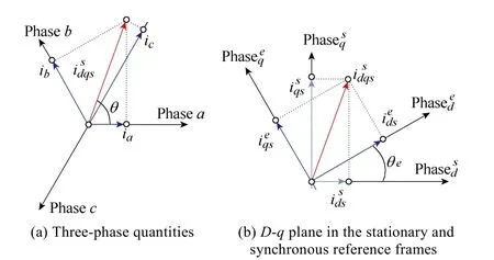
Fig.2 Reference coordinate systems and coordinate rotations
2.1.2 Coordinates transformations
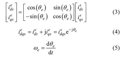
Thed-qreference frame defined by (1) and (2) is fixed in space and will be referred to as a stationary reference frame. Variables referred to this reference frame will be denoted by a superscript “s”. The twophase components defined by (1) and (2) can be referred to an arbitrary reference frame forming an angleθewith the stationary reference frame, as shown in Fig.2. This transformation is defined by (3) and (4) for the case of scalar and complex vector notation respectively.Variables referred to this reference frame are denoted by a superscript “e”. This transformation is especially important when the reference frame rotates at the electrical frequencyωeof the electro-magnetic variables(currents, voltages, flux-linkages) (5). This rotating reference frame is referred to as synchronous reference frame.
2.2 Modeling of three-phase loads
D-qmodels play a major role in the analysis of three-phase systems, including electric AC machines.Though scalar and complex vector representations can be used for this purpose and will eventually provide the same results, each has its own advantages and disadvantages. Following a three-phase RL load will be used to discuss the different options and to analyze the current regulation problem in Section 3. Similarities between the current control problem of a three-phase RL load and a three-phase electric machine will be shown in Section 2.2C.
2.2.1 Scalar model of symmetric RL load
The current to voltage relationship of a three-phase,symmetric RL load with isolated neutral connection(Fig.3a), is described using matrix notation by (6). Since the neutral of the RL load is isolated (7) must hold.

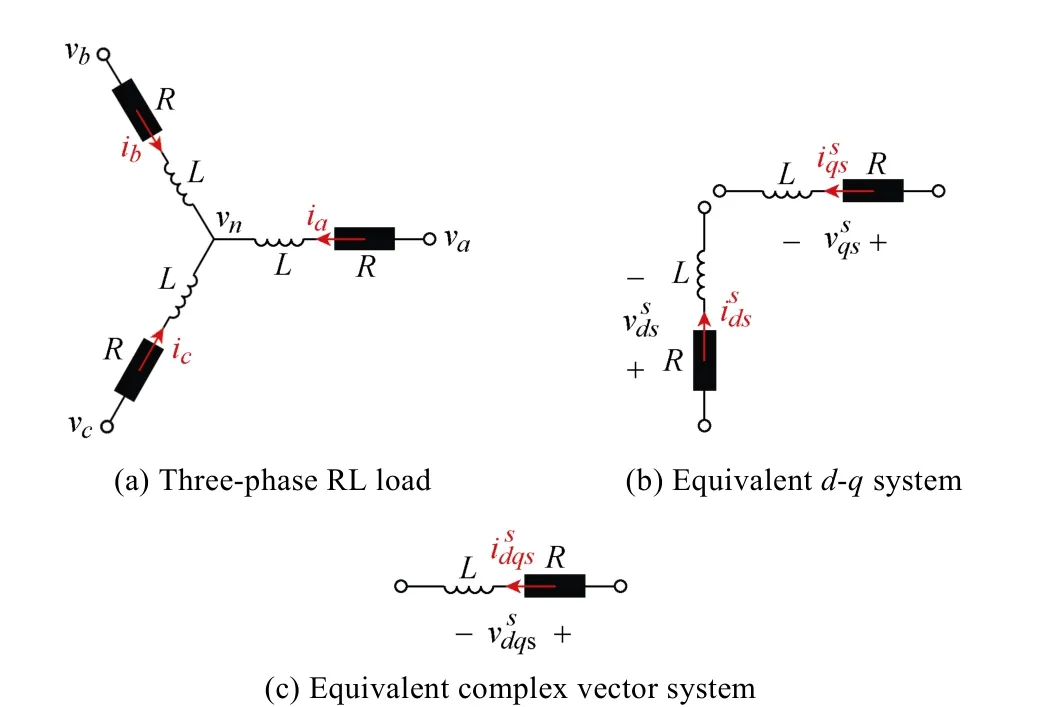
Fig.3 RL load models

Applying (1) to both the currents and the voltages in(6) the two-phase equivalent system (8) is obtained. The reduction from three to two dimensions just recognizes the fact that the three-phase currents are not independent.The equivalent circuit is shown in Fig.3b[8].

It is useful from a modeling and control perspective to transform (8) to a synchronous reference frame. This is done by applying (3) to both the current and the voltages in (8), with (9) being obtained (the corresponding block diagram can be found in the right side of Fig.10). It is observed that in the synchronous reference frame there is cross-coupling betweend- andq-axis (ωeLterms).

2.2.2 Complex vector model of a symmetric RL load
The complex vector transfer function describing an RL load in the stationary reference frame (10) is obtained by taking the Laplace Transform to currents and voltages in (8)[8], whereYs(s) corresponds to the stator admittance.

This transfer function can be referred to as a synchronous reference frame (12) using (4), (5) and considering (11)[7]. The equivalent circuit is shown in Fig.3c, the corresponding block diagram being shown on the right side of Fig.9.

Comparing (8) and (9) with (10) and (12) is observed that the complex vector representation reduces both the order of the system and the number of inputs and outputs from two to one. It is also seen from (12) that poles (and zeros) in complex transfer functions do not need to exist in conjugate pairs as opposed to the scalar representation.
2.2.3 Complex vector model of an induction machine
For the sake of simplicity, an RL load has been chosen in Section 2.2 to introduce scalar and complex vector models of three-phase AC systems. However, the main target of this work is the study of current regulators for electric drives. Regardless of the significant differences between an electric machine and an RL load, they share some key properties, meaning that most of the conclusions reached for the current regulation of an RL load apply to the electric machine case. The induction machine will be used to illustrate this.
The nonlinear state equations in the synchronous reference frame governing the electrical and electromagnetic behavior of an induction motor using complex vector notation, with the stator current and the rotor flux as the state variables are (13) and (14)[7]. The corresponding block diagram is shown in Fig.4.
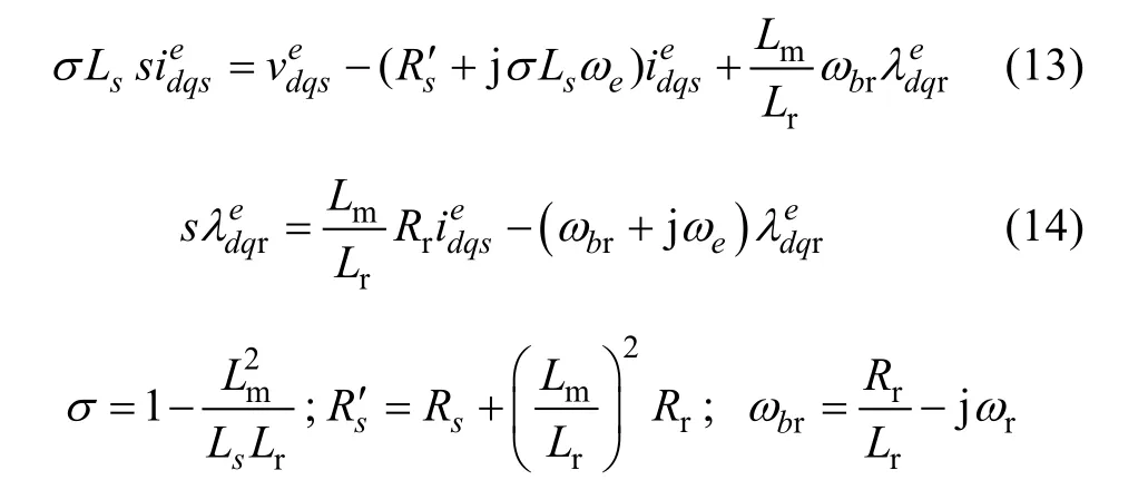
The last term in (13) is the back-emf. Comparing(13) and (12) it is observed that the induction machine is equivalent to an RL load with the back-emf behaving as a disturbance voltage (see Fig.4). Two different approaches can be followed for the extension of the RL load analysis to the electric machine case. The back-emf for the second case can be decoupled, the resulting system then coinciding with (12). Alternatively, the behavior of the induction machine can be studied from the response of an RL load to a disturbance (back-emf)voltage[3]. This is further discussed in Section 4.
3 Voltage needs and limits
The current regulator provides the voltage command to the three-phase inverter feeding the machine.Understanding inverter behavior and limits will be key for proper current regulator design and drive operation.

Fig.4 Complex-vector block diagram of a current regulated three-phase induction machine
3.1 Voltage needs
Fig.5 shows a schematic representation of the stator voltage vs. frequency for an induction machine. It is noted that the discussion following also applies for other types of AC machines. When the machine is operating in steady state, the difference between the stator voltage and the inverter voltage limit is the voltage margin available for the current regulator transient operation.This margin reduces as the frequency increases mainly due to the back-emf (last term in the right side of (13)),eventually affecting to the current regulator performance.Some relevant aspects must be considered in this case:
●Selection of current commands to produce the desired torque depends on the strategy used by outer control loops (field weakening, MTPA, ...)[10]. Discussion of this issue is beyond the scope of this paper.Independent of the strategy being used, current commands must be chosen such that in steady state there is enough voltage to produce the desired currents.
●Voltage margin reduction at high speeds will unavoidably penalize the current regulator transient response. It is critical to guarantee that this does not jeopardize system integrity due e.g. to current overshoots or even instability of the current loop.
●When the current regulator operates with a reduced voltage margin, it is important to ensure that the current regulator utilizes all the available DC link voltage[3,10-12].This involves both proper current regulator design and inverter modulation strategy.
DC link voltage utilization is discussed in the next subsection, transient operation of the current regulator under transient constraints being discussed in Section 5.
3.2 Inverter operation and voltage limits
Fig.6a shows the voltage limits in thed-qplane for a three-phase, two-level inverter. The maximum fundamental voltage component that can be supplied by the inverter is determined by the DC bus voltage and the modulation strategy. Operation of the inverter when the fundamental voltage is constrained to the inscribed circle is commonly referred to as linear operation. It is possible to increase the fundamental voltage further by allowing the voltage command to move on the hexagon limits, which is referred to as overmodulation. The maximum fundamental output voltage corresponds to six-step operation. In this mode the voltage vector remains on each corner of the hexagon for one sixth of the fundamental cycle[3,14-17].

Fig.5 Schematic representation of the voltage vs. speed characteristics of an induction machine in steady state(Voltage margin accounts for the voltage available to the current regulator for transient operation)
It is up to the designer to constrain the voltage command to the linear region or to use overmodulation.Choosing one option or the other involves a trade-off among: ①The maximum fundamental voltage (and consequently current and torque); ②Voltage (and consequently current) harmonic content, which will affect to torque quality; and ③Inverter switching losses.Table 1 summarizes the main properties for different modes of operation of the inverter.
A relevant issue in drives configured to operate in overmodulation or even six-step is the transition among the different modes. Voltage commands coming from the current regulator which are outside the hexagon (see Fig.1) cannot be produced physically by the inverter and must be limited, several methods have been proposed for this. Using the intersection between the commanded voltage and the hexagon is likely the most intuitive solution, and is referred to as Minimum phase error in Fig.6b[11,13]. A concern with this method is that the increase of the fundamental component of the output voltage vs. commanded voltage in the over modulation region is modest (see Fig.7) and cannot provide six-step.Minimum distance (see Fig.6b) projects the original voltage command on the hexagon[11,13].Though this strategy produces a larger fundamental voltage, it cannot provide six-step either unless the voltage command becomes infinite. In the method proposed in [14](Constant magnitude in Fig.6b) the voltage command is rotated until it intersects the hexagon. An appealing property of this method is that it quickly produces six-step (whenever, see Fig.7). Discussion on transition between different modes of operation of the inverter and the reconfiguration of the control loops can be found in [11].

Table 1 Modes of operation of the inverter
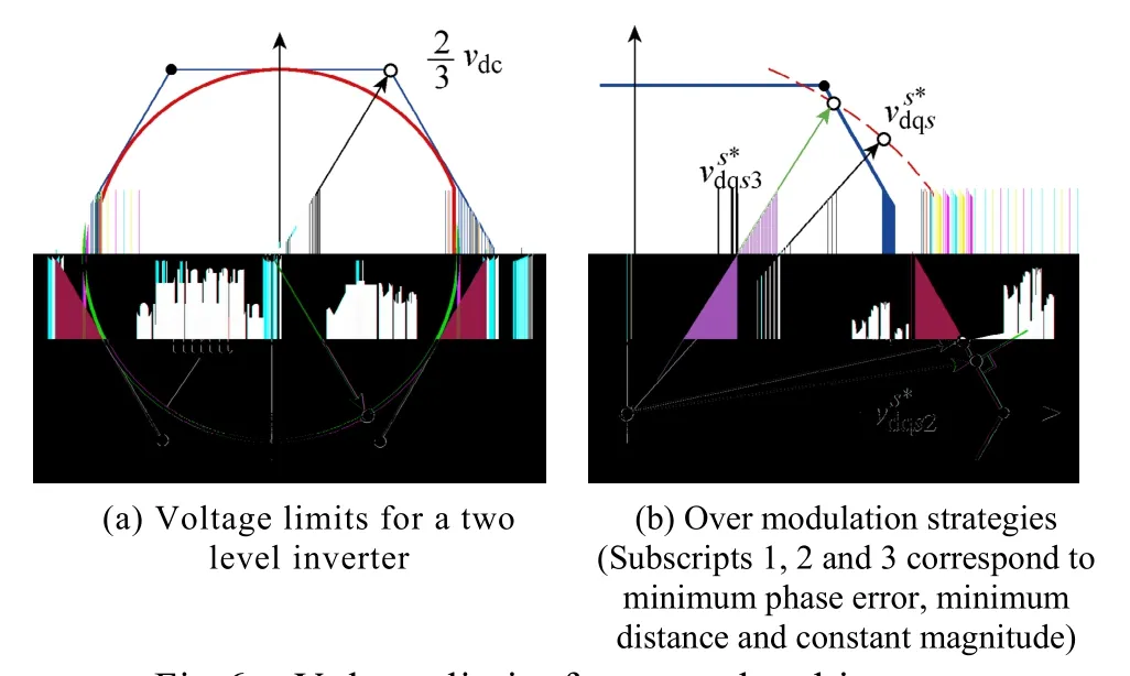
Fig.6 Voltage limits for a two-level inverter
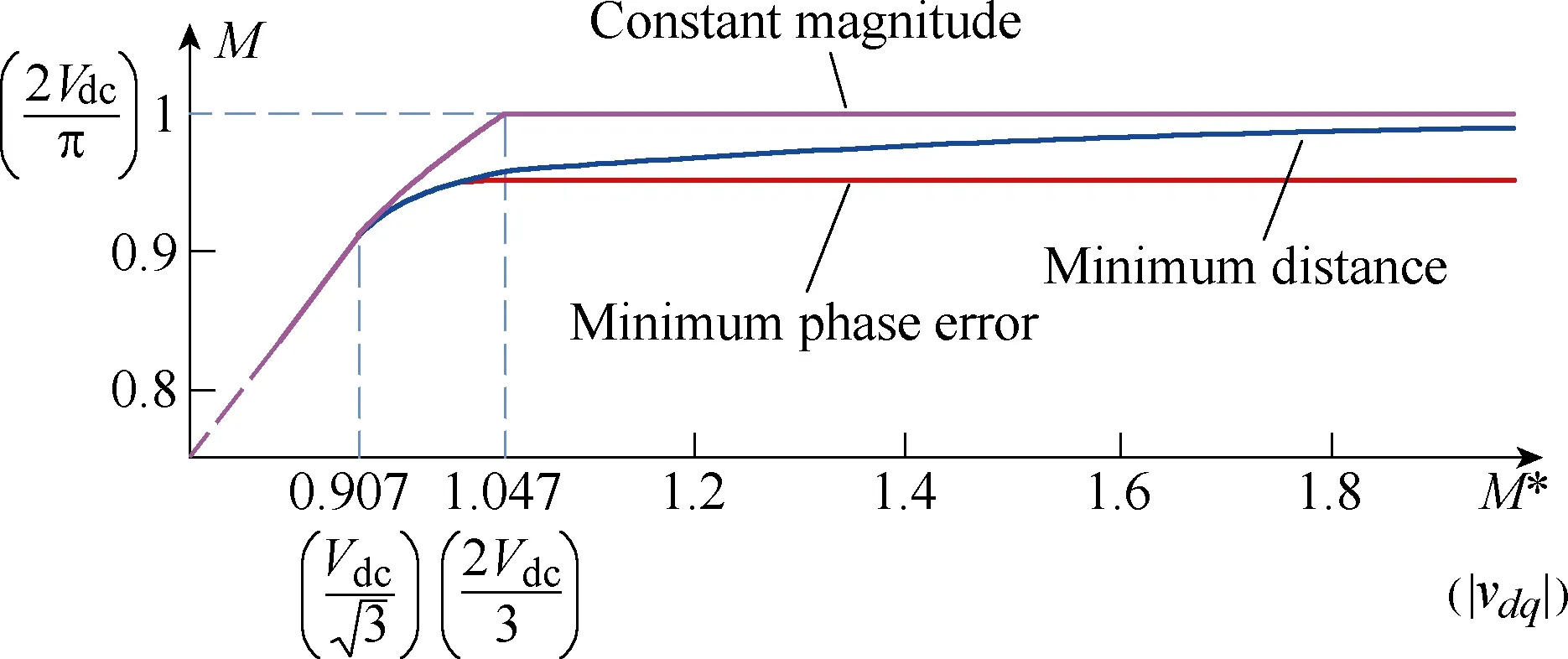
Fig.7 Fundamental component of the output vs. reference voltage for different overmodulation strategies(Modulation index M=1 corresponds to the maximum fundamental voltage that can be supplied by then inverter,which occurs for six-step operation)
3.3 PWM update and current sampling
Since synchronous PI current regulators are always implemented digitally, different strategies can be used for the PWM update and current sampling. The discussion following assumes that the PWM uses a triangular carrier but also applies for Space Vector Modulation. Symmetric PWM(Fig.8-left) updates the voltage command once per cycle of the triangular carrier,while Asymmetric PWM(Fig.8-right) updates the voltage command twice per switching period[3]. In both cases, updates must occur at the peaks of the carrier.Asymmetric PWM is preferred as it reduces by two the delay intrinsic to the PWM operation, enabling higher current regulator bandwidths. This can be of great interest in drives operating at low switching frequencies,but is at the price of doubling the computational burden of the current regulator.
Sampling the currents at the peaks of the triangular carrier(commonly known as synchronous sampling, see Fig.8c) is the preferred strategy in AC drives[18].Synchronous sampling is easy to implement and is claimed to provide the mean value of the current over the switching period, getting rid therefore of switching harmonics without the use of an anti-aliasing filters,which otherwise would compromise the current regulator bandwidth.
It is finally noted that traces shown in Fig.8 use a constant switching frequency. Modulation strategies using variable switching frequency have also been proposed, as synchronized PWM[1,3]and random PWM[19], which are of common use e.g. in electric traction.

Fig.8 Waveforms and current sampling for the case of symmetric and asymmetric PWM
4 Synchronous PI current regulators
The transformation of three phase loads to a reference frame rotating synchronously with the excitation frequency was already shown to have the appealing property of transforming sinusoidal signals into dc signals. A PI regulator implemented in this reference frame should therefore provide zero steady-state error, independent of the excitation frequency. This form of controller is denoted as a synchronous PI current regulator and can be considered the standard in current controlled AC drives[5-6].
4.1 Classical synchronous PI current regulators
In its simplest implementation, the PI current regulator shown in the synchronous reference frame is given by (15), its block diagram is shown in the left side of Fig.9.
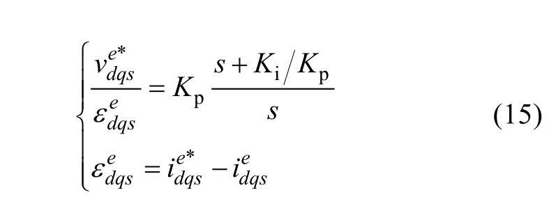
The scalar representation of this controller can be seen in the left side of Fig.10 (without dashed lines). The regulator can be transformed into a stationary reference frame using (4) and (11), (16) being obtained.

An effective way to tune the current regulator gains is zero-pole cancellation. The controller zeroKiKpis selected to be equal to the(estimated) cut-off frequency of theRLload,ωs(17). The proportional gainKpis then selected to obtain the desired closed-loop bandwidthωbw(in rad/s).

Fig.9 Complex vector block diagram of a current regulated RL load using a classical synchronous PI current regulator,shown in a synchronous reference frame

Fig.10 Scalar block diagram of a current regulated RL load using a classical synchronous PI current regulator, shown in a synchronous reference frame. Dashed lines correspond the complex vector PI current regulator in Fig.16

The closed-loop transfer function in the stationary reference frame obtained from (10) and (16) is (18).
Bandwidth and synchronous frequency are normalized to p.u. by dividing by the system bandwidthωs=R/L

A suitable tool to evaluate the behavior of the closed loop system is (18) the Frequency Response Function(FRF), which is obtained by makings= jω[7-8]. Fig.11 shows the FRF for the transfer function in (18). It is noted that as complex vectors can rotate both forwards (positive frequencies) and backwards (negative frequencies), the FRF must include both positive and negative frequencies.Furthermore, use of a logarithmic frequency scale is not possible unless some trick is implemented to avoid the frequency zero crossing. Two important facts are noticed from Fig.11.
●In all the cases the FRF has a unity gain and zero phase shift at the synchronous frequency. This means that the current regulator guarantees perfect tracking (no error) in steady state. This holds for any synchronous frequency, regardless of current regulator bandwidth.
●A resonance in the FRF occurs near the synchronous frequency whenever the synchronous frequency is different from zero. This resonance increases as the synchronous frequency increases.
Transients in the current will excite the resonances shown in Fig.11, eventually resulting in a degradation of the current regulator dynamic response. Fig.12 shows the time response of the synchronous PI current regulator to a step-likeq-axis current command for different values of the synchronous frequency. As the synchronous frequency increases, current control degradation(overshoot, increased settling time and cross-coupling betweend- andq-axis) is readily visible.
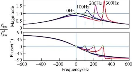
Fig.11 Classical synchronous PI current regulator FRF for different fundamental frequencies. Current regulator was tuned for 200Hz bandwidth
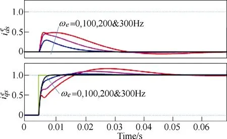
Fig.12 Classical synchronous PI current regulator time response, shown in a synchronous reference frame, to a step-like command in the q-axis for different fundamental frequencies
The results shown in Fig.12 were obtained for certain values of the system pole and current regulator bandwidth. The behavior of the closed-loop system depends on the synchronous frequencyωeand closedloop bandwidthωbwvs. load cut-off frequencyωs(17).Fig.13a shows the resonance peak of the FRF, while Fig.13b shows the overshoot of the time response to a step-like command, as a function of the synchronous frequency and closed-loop bandwidth, normalized in p.u. of the system cut-off frequencyωs. The risks of operating at(relative) high synchronous frequencies with(relative) low current regulator bandwidths are evident from this figure.
Classical synchronous PI current regulator time response, shown in a synchronous reference frame, to a step-like command in thed- andq-axis for two different fundamental frequenciesωbw=200×2πrad/s.
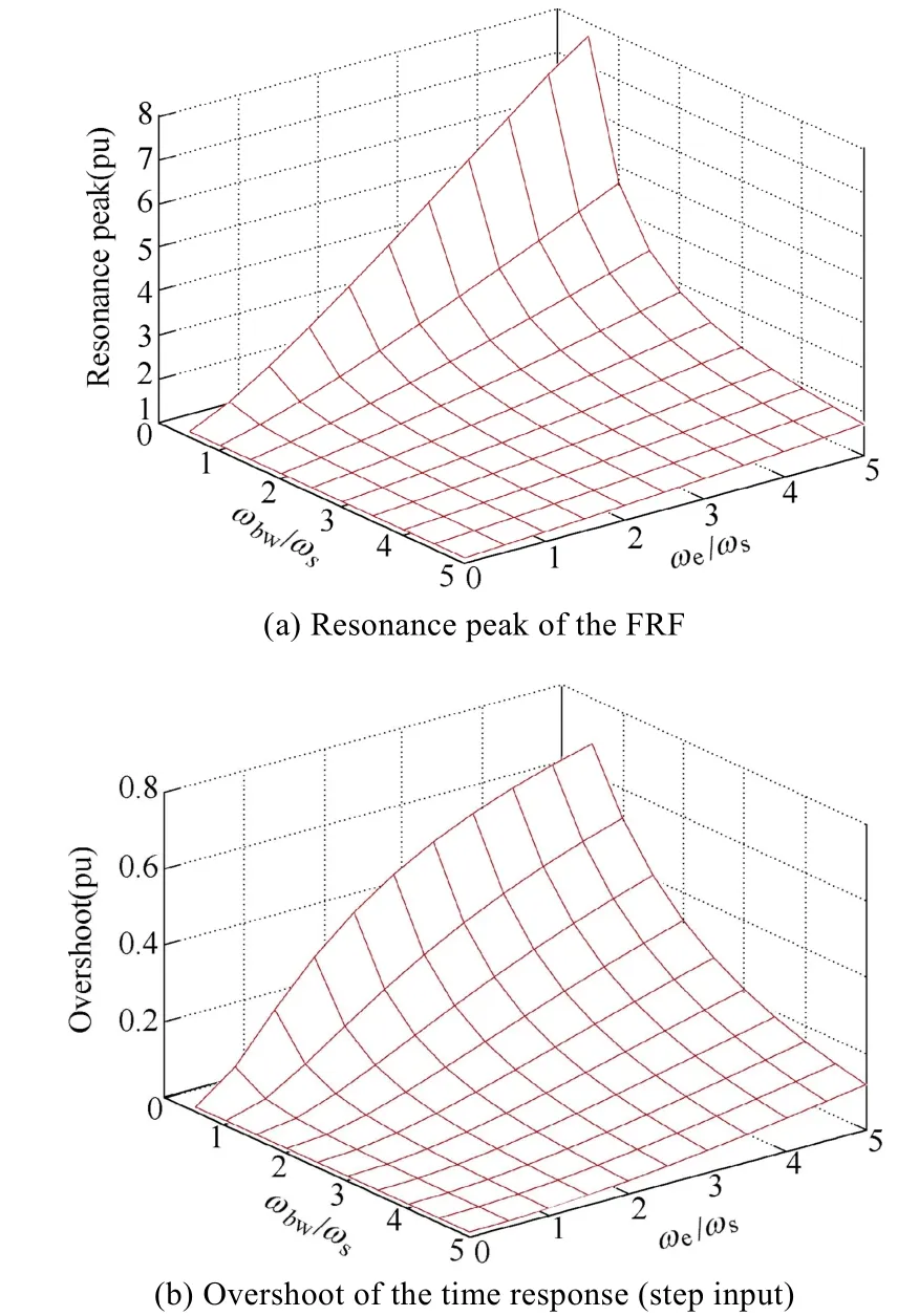
Fig.13 a) resonance peak and b) overshoot in the time response of the FRF vs. bandwidth and synchronous frequency of a classical synchronous PI current regulator(Bandwidth and synchronous frequency are normalized to p.u. by dividing by the system bandwidth ωs=R/L)
Experimental results showing the response of the synchronous PI current regulator to step-like commands in theqanddaxis current for two synchronous frequencies of 50Hz and 200Hz are shown in Fig.14.These results confirm the deterioration (overshoot,cross- coupling) of the current regulator response as the synchronous frequency increases.
An ideal synchronous PI current regulator should show a response independent of the synchronous frequency when viewed in a synchronous reference frame. Two different approaches to achieve this are discussed in the next subsections: ①Cross-coupling decoupling and ②The complex-vector PI current regulator[7-8]. This last one is equivalent to the internal model control discussed in [9].
4.2 Synchronous PI current regulators with crosscoupling decoupling
A behavior independent of the synchronous frequency can be achieved using the scheme shown in Fig.15. The current controller is seen to include a gain equal jωeLin the feedback path which compensates the effect of the load cross-coupling. It is noted that the decoupling block implemented by the controller uses and estimation of the load inductance,ˆLwhich will differ from the actual value. The effects of the inductance estimation errors must therefore be considered[7-8]. It is also noted that there is no error in the fundamental frequencyωe, as this frequency is set by the digital signal processor implementing the control.
4.3 Complex-vector synchronous PI current regulator(internal model control)

Fig.15 Current regulated RL load using a classical synchronous PI current regulator with cross-coupling decoupling, shown in a synchronous reference frame
The idea behind the complex-vector synchronous PI current regulator is to use the controller zero to cancel the system pole. This is in principle the same concept discussed in Section 4.1. However, the cancellation discussed in Section 4.1 was only effective for the case of a fundamental frequency equal to zero. The complexvector synchronous PI current regulator (19) considers for the zero placement the displacement of the load pole with the fundamental frequency. This design is shown in Fig.16.

Assuming exact zero-pole cancellation (17), the closed- loop transfer function in the stationary reference frame is equal to (20), which in a synchronous reference frame transforms to (21).

Fig.17 shows the FRF for both the synchronous PI current regulator with cross-coupling decoupling in Fig.15 and the complex vector synchronous PI current regulator in Fig.16, obtained makings=jωin (20).Perfect matching between system and controller parameters (17) is assumed. The FRF shifts with the fundamental frequency, but its shape remains invariant,contrary to the FRF shown in Fig.11 for the classical synchronous PI current regulator. In a synchronous reference frame, the closed-loop transfer function (21) is seen to be that of a first-order system with the desired bandwidthωbwand independent of the synchronous frequency.

Fig.16 Current regulated RL load using a complex vector PI current regulator, shown in a synchronous reference frame
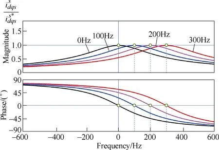
Fig.17 Synchronous PI current regulator with cross-coupling decoupling and complex vector PI current regulator FRF for different fundamental frequencies(Current regulator was tuned for 200Hz bandwidth)
Complex vector synchronous PI current regulator time response, shown in a synchronous reference frame, to a step-like command in thed- andq-axis for two different fundamental frequenciesωbw=200×2πrad/s.
Experimental results showing the response of the complex vector synchronous PI current regulator to step changes in thed- andq-axis current commands are shown in Fig.18, for two synchronous frequencies of 50Hz and 200Hz. These results confirm that the response of the current regulator is not affected by the synchronous frequency. The synchronous PI current regulator with cross-coupling decoupling provides similar performance, and as such the results are not included due to space constraints.
It is finally noted that while both the synchronous PI current regulator with cross-coupling decoupling and the complex vector design provide the same performance ideally, the second is more robust against errors in the system parameters (i.e. incorrect zero-pole cancellation (17))[8].
4.4 Back-emf effects and compensation
As discussed in Section 2.2C, an electric machine can be modeled as an equivalent RL load with the back-emf acting as a disturbance (see Fig.4). Back-emf occurs at the synchronous frequency and is proportional to the rotor speed and the flux linkage. On the other hand, it is observed from Fig.5 that the voltage drop in the stator transient impedance, i.e. the voltage requested by the current regulator to inject the desired current into the equivalent RL load, is relatively small. Therefore,at medium-high speeds the back-emf can be viewed as large disturbance interfering with a small control signal.
The effects due to the back-emf can be analyzed using the transfer function between output current and back-emf voltage. These can be readily obtained from(12), (15) and (19), being (22) for the synchronous PI,(23) for the synchronous PI with cross-coupling decoupling and (24) for the complex vector synchronous PI current regulators.


Fig.18 Experimental results for an RL load(R=1.1Ω, L=3.7mH) Complex vector synchronous PI current regulator time response (shown in a synchronous reference frame, to a step-like command in the d- and q-axis for two different fundamental frequencies, ωbw=200×2πrad/s)

Fig.19 shows an example of the response of the different current regulator designs to a step-like change of the back-emf voltage. Several conclusions are reached:
●The DC gain is always zero, meaning that in steady state the disturbance voltage is fully compensated by the current regulator. This was expected as disturbance rejection to DC signals in steady state is inherent to the PI controller. The settling time is similar for all the designs.
●The back-emf voltage is a function of the rotor flux and the speed. In many applications speed dynamics are significantly slower than current regulator dynamics, while flux will either remain constant or will vary according to speed(field weakening). Consequentlywill change slowly. Its effects are therefore easily compensated by the current regulator.
●An exception can be servo drives with low mechanical inertia, for which speed dynamics might not be negligible compared to current dynamics. Back-emf decoupling can be used in this case.
●The use ofactive resistancein the feed-back path(see in Fig.20) is an effective mechanism tothe stiffness of the current regulator against.This fictitious resistance adds to the physical resistance but without consuming power[7]. Current regulator (25) and gain selection (26) are easily deduced from (19) and (17) respectively. The active resistance is selected asRa=ωbwL-Rin [12,21].

Fig.19 Simulated response of different current regulator designs to a step-like disturbance voltage (shown in a synchronous reference frame. ωbw= ωe=200×2πrad/s;Ra=2R for the active resistance case)

Fig.20 Current regulated RL load using a complex vector PI current regulator with active resistance Ra (shown in a synchronous reference frame)

Benefits of active resistance can be observed in Fig.19.
4.5 Current regulator representation using a statefeedback structure
The synchronous current regulator (25) can be represented as a state-feedback regulator, augmented with integral action and the reference feedforward[20-21],whereKtis the reference-feedforward gain,Kiis the integral gain, andK1is the state-feedback gain. In a general case, the gains are complex, which is marked with boldface symbols.

This structure, illustrated in Fig.21, is useful for better understanding the direct discrete-time design in Section 5.
Using (12) and (27) with the assumptionthe closed loop response is obtained,

The two closed-loop poles can be arbitrarily placed by means ofKiandK1and the one zero by means ofChoosing the gains (29) makes the regulator in (27)mathematically equivalent to the regulator (25) with the gain selection in (26).

5 Digital implementation
As explained before, synchronous current regulators are implemented digitally. The implementation can be based on ①approximation of the continuous-time design; or ②direct discrete-time design.
The first approach is more straightforward to apply.The continuous-time design is simply discretized by means of the Euler (or Tustin) method and the angular errors due to the computational delay and the PWM are compensated for in the coordinate transformation.However, the sampling frequency should be at least 10~20 higher than the closed-loop bandwidth and the maximum synchronous frequency. If this requirement is not fulfilled, the actual closed-loop system deviates significantly from the desired one due to discretization errors, leading to the cross-coupling between the axes,oscillations, and even instability.
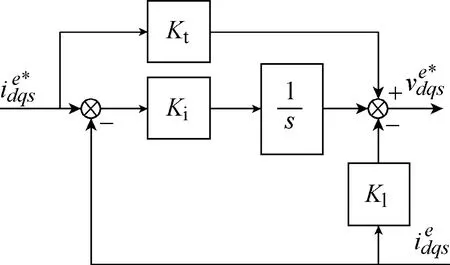
Fig.21 Synchronous current regulator in the form of state-feedback regulator
In the direct discrete-time design, the exact sampled-data model of the system(including the sampling and hold effects) is first developed and the regulator is then designed directly in the discrete-time domain. The system delays can be properly taken into account, which enables significantly better performance and robustness at low sampling frequencies.
In the following, discrete-time regulators resulting from these two fundamentally different approaches are presented using the same regulator structure. The sampled-data model of the system to be controlled is first developed and a discrete-time control algorithm is then defined. The gains resulting from the two approaches are then given.
The PWM is modeled with the ZOH in stator coordinates. An inherent computational delayz-1of the digital processor and the inverter voltage saturation are taken into account.
The anti-windup mechanism based on the realizable reference is also included.
5.1 Voltage saturation and sampled-data model
Fig.22(a) shows the system seen by the digital current regulator[21-23]. This model includes the following important phenomena:
●The phase currents are sampled in synchronism with the PWM(cf. Fig.8). Therefore, the switchingcycle-averaged models and quantities can be used in modeling and control design.
●The PWM is modeled using the zero-order hold(ZOH) in stator coordinates[21-22], i.e., the actual stator voltage(t) in stator coordinates is piecewise constant between two consecutive sampling instants.

Fig.22 Digital implementation (The PWM is modeled with the ZOH in stator coordinates. An inherent computational delay z-1 of the digital processor and the inverter voltage saturation are taken into account)
●The inverter voltage is limited, cf. Fig.6. The limited(realizable) voltage reference is denoted byIf the voltage referenceis inside the voltage hexagon,holds.●The computation of the new voltage command takes finite time, typically less than one sampling period. The new voltage command is applied in the beginning of the next sampling period, which causes one sampling-period delay in the control system. This computational delay should be considered in the control design, unless the sampling frequency is very high compared to the bandwidth and to the synchronous frequency.
Fig.22(b) shows a sampled-data model equivalent to Fig.22(a). The development of the model is briefly explained in the following. In stator coordinates, the sampled current is (30), where the pulse-transfer function (31) is obtained from (10) as [20].

Transforming this model to synchronous coordinates leads to


The model in Fig.22(b) is directly applicable to nonsalient permanent magnet synchronous machines and to induction machines. Using the above-mentioned assumptions, the closed-form sampled-data model for salient synchronous machines is derived in [21]. The nonlinear saturation characteristics can also be included in the model[24]. The hold-equivalent models can also be expressed using the series expansions[20-21].
5.2 Control algorithm
The discrete-time state-feedback control algorithm,analogous to (27), is considered

whereis the integral state,Kiis the integral gain,Ktis the feedforward gain, andK1andK2are the state-feedback gains. Fig.23 shows the corresponding block diagram, where also the anti-windup mechanism is included and it will be discussed in Section 5.6.

Fig.23 Discrete-time synchronous current regulator
The computational delay increases the order of the discrete-time system as compared to the continuous-time system. However, the full-state feedback can still be easily realized using (33) and the gainK2in (35). The realizable voltage reference needed in (33) can be obtained from the PWM or it can be calculated from the simple geometry of the voltage hexagon[17,24].Naturally, the proper coordinate transformations between stator and synchronous coordinates are needed in both cases.
It is also worth noticing that the control algorithm given in (34)~(35) can be used for approximating the continuous-time designs, as will be further discussed in Section 5.4.
5.3 Closed-loop system
Using (32)-(35), the closed-loop response of the system is obtained

where the coefficients depend on the motor parameters and the controller gains

The model in (36) can be used for analysis of the closed-loop response as well as the pole and zero locations resulting from different gain selections.
5.4 Approximation of the continuous time design
The gains of the discrete-time regulator (34)~(35)can be determined based on the continuous-time regulator design. When approximating continuous-time designs, the angular error of 3/2ωeTcaused by the ZOH and computational delays should also be compensated for[25]. Embedding this compensation into the gains given in (29) yields

When these gains are used in (35), the continuoustime integrator is approximated with the Euler method,but the control performance would be essentially the same for the Tustin method as well. The problems at low sampling frequencies originate from the delays, which are omitted in the continuous-time designs; only the angular error of the delay is compensated for in(42)~(45).
Fig.24(a) shows example results, measured using a 6.7kW synchronous reluctance motor drive[24]. Even if the load is different, essentially the same design principles are used as in this paper. The cross-coupling and overshoot seen in the response originate mainly from the digital delays, even if the sampling frequency is 25 times the closed-loop bandwidth and about 30 times the synchronous speed. If the sampling frequency were increased, the response would better match the designed one.
The green dashed line shows the response of the discrete-time system without the computational delay.
5.5 Direct discrete-time design
For the direct discrete-time design, the gains can be solved from (37)~(41) as


Fig.24 Experimental results for a 6.7kW synchronous reluctance motor drive rotating at ωe=160×2πrad/s
Due to the full-state feedback, the poles can be arbitrarily placed by choosing the characteristic coefficientsa0,a1anda2. The open-loop polez= 0,originating from the computational delay in (33), is already in the optimal location, thus it is feasible to choosea0=0. The direct discrete-time equivalent of the regulator (25) is obtained by choosing the other coefficients as [21]:


The step responses corresponding to (21) and (51)are compared in Fig.25. Settingβ= 0 (or, equivalently,settingωbwto infinity) would give the dead-beat response. This choice is not recommended, however,due to high sensitivity to the model parameters.
The tuning of the control system is simple, i.e.,the same input parameters are needed as in the continuous-time design:L,R,Raandωbw. It can also be realized that the computationally complexity resulting from the direct discrete-time design (46)~(49) is not much more than that of the continuous-time design(42)~(45). Naturally, the computational efficiency of the algorithm can be optimized in the both cases as compared to the representation shown in Fig.23.

Fig.25 Step responses of the continuous-time system (21)and the discrete-time system, where β =e-ω bwT(The green dashed line shows the response of the discrete-time system without the computational delay)
Fig.24(b) shows example results, measured using the discrete time design with the 6.7kW synchronous reluctance motor drive. It can be seen that the control response matches very well to the designed one. If desired, the sampling frequency could be lowered.
5.6 Anti-windup based on the realizable references
The current regulator should implement mechanisms for guaranteeing proper operation under voltage constraints. If the voltage referenceis outside the voltage hexagon, cf. Fig.6, the control loop becomes nonlinear. The voltage reference may exceed the limit for large current reference steps, especially at large speeds(cf. Fig.7). This inverter voltage saturation will cause the integral state of the regulator to wind up unless some suitable anti-windup mechanism is applied.
The anti-windup mechanism can be designed based on the concept of realizable references[9,12-13,26]. The unlimited (ideal) voltage referenceis given by(35). If the realizable current referencewere applied to the regulator instead of, the unlimited voltage would equal the realizable voltage reference, i.e.,

The realizable current reference (54) can be solved from (35) and (54).

which is applied for the integrator according to Fig.23.This mechanism has no effect in the linear modulation range whereholds.
6 Conclusions
Design and implementation of synchronous PI current regulators for AC drives has been addressed in this paper. Both complex vector and state feedback approaches have been used. Tuning methodology, effects due to discretization and the associated delays, and effects due to voltage constraints have also been considered. It is concluded that, if properly designed and tuned, synchronous current regulators can provide excellent performance even under adverse conditions(low switching frequency vs. fundamental frequency ratio). On the contrary, ignoring aspects such as crosscoupling, the delays intrinsic to digital control systems,or the existence of severe voltage constraints when the drive operates at high speeds, can produce a serious degradation of the control, and even compromise its stability.
 Chinese Journal of Electrical Engineering2018年3期
- Chinese Journal of Electrical Engineering的其它文章
- Prognostic Condition Monitoring for Wind Turbine Drivetrains via Generator Current Analysis
- A Review of Data-Driven Prognostic for IGBT Remaining Useful Life
- Thorough Validation of a Rotor Fault Diagnosis Methodology in Laboratory and Field Soft-Started Induction Motors
- Circuit Implementation of Power Converter for High-Speed Switching Operations
- Study of the Characteristics and Suppression of EMI of Inverter with SiC and Si Devices
- Capacitive DC Links in Power Electronic Systems-Reliability and Circuit Design
