Prognostic Condition Monitoring for Wind Turbine Drivetrains via Generator Current Analysis
(Power and Energy Systems Laboratory, Department of Electrical and Computer Engineering,University of Nebraska-Lincoln, Lincoln, NE 68588-0511, USA)
Abstract: Maintenance costs account for a significant portion of the total cost of electricity generated by wind turbines. Currently in the wind power industry, maintenance is mainly performed on regular schedules or when significant damage occurs in a wind turbine making it inoperable, instead of being determined by the actual condition of the wind turbine. Among the total maintenance costs,approximately 25%~35% is related to regularly scheduled preventive maintenance and 65%~75% to unscheduled corrective maintenance. To reduce the failure rate and level and maintenance costs and improve the availability, reliability, safety, and lifespans of wind turbines, it is desirable to perform condition-based predictive maintenance for wind turbines, which will require a high-fidelity online prognostic condition monitoring system(CMS) for fault diagnosis and prognosis and remaining useful life(RUL) prediction of wind turbines. Most of the existing wind turbine CMSs are based on vibration monitoring and have no or limited capability in fault prognosis and RUL prediction. Compared to vibration monitoring, the prognostic condition monitoring techniques based on generator current signal analysis proposed recently have significant advantages in terms of cost, hardware complexity,implementation, and reliability. This paper discusses the principles and challenges of using generator current signals for prognostic condition monitoring of wind turbine drivetrains and presents an overview of recent advancements in this area.
Keywords: Current signal, drivetrain, fault diagnosis, fault prognosis, prediction, prognostic condition monitoring, remaining useful life(RUL), wind turbine.
1 Introduction
Compared to the turbine generator systems spinning in the traditional thermal and hydro power plants,wind turbines have relatively higher failure rates due to the highly varying operating conditions and harsher environments, and therefore, require more frequent inspection and maintenance. Currently, in the wind power industry, maintenance is primarily performed based on predetermined schedules(i.e., preventive maintenance) or to repair or replace failed parts(i.e.,corrective maintenance). In practice, many preventive maintenance actions are not necessary because the wind turbines are still in healthy condition. On the other hand,to reduce maintenance costs, it is desirable to perform maintenance in a timely manner before a small failure turns into a large or catastrophic failure. For instance,the failure of a $1,500 bearing, if not repaired or replaced in time, could result in a $100,000 gearbox replacement, a $50,000 generator rewind, and $70,000 in expenses to replace other failed parts[1]. According to a General Electric(GE) report[2], a $5,000 bearing replacement can turn into a $250,000 project that involves cranes, a service crew, gearbox replacement,and generator rewind, not including the loss of electricity generation during downtime.
Since wind turbines are usually situated on high towers, installed in remote areas, and distributed over large geographic regions, the attendance for maintenance is restricted by factors such as the availability of manpower, parts, equipment, and other required resources as well as weather conditions. For example, no maintenance actions can be performed for wind turbines during bad weather conditions such as storms, snows,high tides, etc. Possible inaccessibility in certain periods of the year can prevent any maintenance actions for a long time, e.g., several weeks, which can cause a significant loss of electricity production during downtime.Therefore, it is expensive to perform maintenance for wind turbines. It was reported by [3-5] that the operation and maintenance(O&M) costs for onshore and offshore wind turbines are on the order of 10%~15% and 20%~35%, respectively, of the total cost of the generated electricity and increase with the age of the wind turbine. Out of the total maintenance costs,approximately 25%~35% is related to preventive maintenance and 65%~75% to corrective maintenance.To make wind energy more cost effective, it is critical to reduce the maintenance costs and downtime of wind turbines.
An effective means to reduce the maintenance costs and downtime of wind turbines is to perform condition-based predictive maintenance before a failure occurs or starts to affect the operating performance or safety of the wind turbine. To achieve condition-based predictive maintenance, the health conditions of wind turbines need to be monitored and prognosed online continuously by a condition monitoring system(CMS).The existing CMSs are typically equipped with dedicated sensors and data acquisition devices to acquire the data that contains the information on the health condition of the wind turbines and dedicated signal processing algorithms to extract the information (features) that are related to possible failures of the wind turbines from the acquired data. The information extracted is then used to perform fault diagnosis to detect, locate, and identify occurring faults and monitor the development of the faults from defects (i.e., incipient faults) into failures.Alarms will be triggered when failures occur and corrective maintenance actions are needed[6-7]. Future CMSs are also expected to perform fault prognosis to predict the development of a defect into a failure, when the failure occurs, and the remaining useful life (RUL)of the wind turbine component with the defect[6].
In the last decade, significant research has been conducted to develop technologies for condition monitoring of wind turbines, with the focus on blades and drivetrain components, including bearings, shafts,gearbox, and generator, because the majority of the maintenance costs and downtime are caused by failures of drivetrain components and blades[6-7]. A variety of signals, such as vibration, acoustic, strain, torque,temperature, lubrication oil parameter, electrical, and supervisory control and data acquisition system (SCADA)signals have been studied to monitor wind turbine health conditions[7]. Since the faults in wind turbine drivetrains usually lead to vibrations of the shafts,vibration signals are most commonly used for condition monitoring of wind turbine drivetrain components[7].For example, the majority of the commercially available CMSs mainly use vibration signals measured from key drivetrain components, such as gearbox, main bearing, and generator[8]. The vibration-based condition monitoring technologies have matured and been standardized by ISO 10816, which provides guidance for evaluating vibration severity in machines operating in the 10~200Hz(600~12,000r/min) frequency range[9-10].However, vibration-based condition monitoring requires installation of additional sensors and data acquisition devices, which can be expensive and intrusive to the wind turbines. In addition, the installed vibration sensors can cause additional issues to the reliability of the wind turbines when the sensors fail. Moreover, the effectiveness and accuracy of vibration-based condition monitoring techniques are affected by sensor locations and are easily contaminated by environmental noise[11].
Compared to vibration signals, the use of electrical(voltage/current) signals measured from generator terminals for condition monitoring of wind turbine drivetrains has following benefits: First, electrical signals are already used in wind turbine generator control systems, and therefore, no additional hardware cost for sensors or data acquisition devices is needed.Moreover, electrical-signal-based methods are reliable,easily accessible, and nonintrusive to the wind turbines because electrical signals can be collected at a convenient location, such as the bottom of the tower.Electrical signals have been used to detect generator electrical and mechanical faults in wind turbines[12-19]. In addition, the output electric power of wind turbines has been used for detecting blade faults as well as mechanical faults in the drivetrain components other than generators[20-23]. The use of electric power needs the measurements of both currents and voltages of the generator. Other than electric power, the work [24-26]used only generator voltage or current signals for wind turbine drivetrain condition monitoring.
However, there are challenges of using electrical signals for condition monitoring of wind turbine drivetrains. First, the fault signatures in electrical signals have low signal-to-noise ratios (SNRs), where signal is referred to as the fault signatures contained in the electrical measurements and noise is referred to as the dominant components of the electrical measurements that are irrelevant to faults. This is due to modulation with the fundamental frequencies and other harmonic components of the electrical signals which are usually nonstationary and noisy. Moreover, online condition monitoring requires continuous online processing of large amounts of low-SNR nonstationary data, which poses high requirements on the computational efficiency and resolution of the signal processing algorithms used for condition monitoring. None of the previous work has sufficiently addressed these challenges. Finally, there was no previous work on fault prognosis and RUL prediction of wind turbines using electrical signals.
Recently, significant advancements have been made in using generator current signals for prognostic condition monitoring, including fault diagnosis and prognosis and RUL prediction, of wind turbine drivetrains under nonstationary operating conditions[27-43]. This paper provides an overview of these advancements. The rest of the paper is organized as follows: Section 2 presents the principles of using generator current signals for prognostic condition monitoring of wind turbine drivetrains. Then, the challenges of using current signals for prognostic condition monitoring of wind turbines are discussed in Section 4. Section 5 presents a prognostic CMS that uses generator current signals for fault diagnosis and prognosis and RUL prediction of wind turbine drivetrains and the major signal processing algorithms used in the CMS. Section 5 provides the validation results for the current-based prognostic condition monitoring algorithms. Finally, Section 6 presents concluding remarks and recommendations for current-based prognostic condition monitoring methods.
2 Principles of using generator current signals for prognostic condition monitoring of wind turbine drivetrains
A fault in a wind turbine drivetrain component usually induces vibrations of the shafts at certain frequenciesfF,1, ...,fF,M, which are called the fault characteristic frequencies in vibration and are usually proportional to the rotating frequencies of the shafts.Due to mechanical couplings between generator and failed drivetrain component(s) as well as electromagnetic coupling between generator rotor and stator, the shaft vibrations at the fault characteristic frequencies modulate the frequency and amplitude of generator stator/rotor current signals. Thus, a wind turbine generator current signali(t) can generally be expressed as follows.

wherekis the harmonic number;Ik(t),fk(t), andφk(t) are the amplitude, frequency, and initial phase of thekth harmonic component, respectively;Ik,j(t),fF,j(t), andφk,j(t) are the amplitude, frequency, and initial phase of thejth fault characteristic frequency in vibration that modulates the frequency of the current signal,respectively. The values ofIk(t),fk(t),Ik,j(t), andfF,j(t)can be time varying due to the nonstationary shaft rotating speed of the wind turbine.
Due to the amplitude modulation of the current signal by the fault-induced vibrations,Ik(t) can be expressed as follows.

whereIw,k(t) is the amplitude of thekth harmonic of the original current signal without modulation; andIk,j(t)andfF,j(t) are the amplitude and frequency of thejth fault characteristic frequency component in vibration that modulates the current signal.
As the result of the frequency modulation, each fault characteristic frequency in vibrationfF,j(t) in (1)will become an infinite number of sidebands around the harmonic frequencyfk(t) in the current signal. Therefore,(1) can be rewritten as follows.

wheremis an integer, indicating that the sidebands occur at multiples of the fault characteristic frequency in vibrationfF,j(t) (j=1, ...,M) away from the harmonic frequencyfk(t).
Wind turbines are mainly equipped with two types of generators: permanent magnet synchronous generators(PMSGs) and doubly-fed induction generators(DFIGs).PMSGs only have stator current signals, for which the harmonic frequencyfk(t) in (3) is proportional to the mechanical shaft rotating frequencyfr(t) of the wind turbine. Since the fault characteristic frequencies in vibrationfF,j(t) (j= 1, ...,M) are also proportional to the shaft rotating frequency, (3) can be rewritten as follows for the wind turbines equipped with PMSGs.

wherenis a real number. Equation (4) indicates that the distances between each harmonic frequency and the fault characteristic frequencies, which appear as sidebands around the harmonic frequency, are proportional to the harmonic frequency.
DFIGs have both stator and rotor current signals.For a DFIG stator current signal, thekth harmonic frequencyfk(t) in (3) is nearly a fixed value because the stator of the DIFG is connected to the power grid. For a DFIG rotor current signal, thekth harmonic frequencyfk(t) in (3) can be expressed as follows.

wherefsis the grid frequency, which is a fixed value;fr(t) is the mechanical shaft rotating frequency of the DFIG, which is usually time-varying; andpis the number of pole pairs of the DFIG.
Equations (1)~(5) indicate that both the amplitude and frequency of the generator current signals contain the information related to faults (i.e., the fault characteristic frequencies in vibration) in wind turbine drivetrains. Therefore, according to the locations and amplitudes of the fault characteristic frequency components extracted from current signals, fault diagnosis (i.e., fault detection, fault type identification,and fault level evaluation) can be performed. In practice,since amplitudes of the fault-induced sidebands around the fundamental frequency are much large than those around the harmonics, onlyk= 1 in (1)~(5) is considered for prognostic condition monitoring.
3 Challenges of using generator current signals for prognostic condition monitoring of wind turbine drivetrains
Although the vibration(s) induced by a fault in a wind turbine drivetrain component are transmitted to the generator and therefore produce signatures in generator current signals, the energy of the fault signatures in a current signal is weaker than that in a vibration signal measured from a vibration sensor near the fault location.This is caused by the energy loss when transmitting the vibration through the shaft(s) of the drivetrain.Therefore, the SNR using generator current signals for condition monitoring is lower than that of using vibration signals.
Additionally, as shown in (1)~(4), a single fault characteristic frequency in vibration becomes multiple/many or even an infinite number of fault characteristic frequencies in current due to frequency and amplitude modulations. As a result, the total energy of a certain fault characteristic frequency component in vibration will be dispersed into multiple/many or even an infinite number of fault characteristic frequencies in current,which further reduces the SNR significantly for fault diagnosis.
Moreover, the fault characteristic frequencies in current signals are time-varying due to nonstationary shaft rotating speeds of the wind turbine drivetrains.Therefore, when the samples of a current signal acquired with the equal time interval within a time window are analyzed in the frequency domain via frequency spectrum analysis, such as the fast Fourier transform(FFT), the fault characteristic frequencies will overlap with each other and with the dominant frequencies of the current signal that are irrelevant to faults or even spread over a wide range of the frequency spectrum. As a result,it will not be able to extract the nonstationary fault signatures(i.e., fault characteristic frequencies) directly from the frequency spectrum of the current signal.
Due to the low SNR and nonstationary fault signatures caused by nonstationary operations of wind turbines, it is very challenging to use generator current signals for prognostic condition monitoring of wind turbine drivetrains. To solve these challenges, advanced signal processing algorithms are needed.
4 Current-based prognostic condition monitoring
This section presents a prognostic CMS that uses generator current signals for fault diagnosis and prognosis and RUL prediction of wind turbine drivetrains under all operating conditions. Fig.1 illustrates the schematic of the prognostic CMS, which consists of several functional modules, including signal conditioning, fault feature extraction, fault diagnosis,fault prognosis, RUL prediction, alarm management, and equipment management. The conditioned current signal can also be used to assist other signals, such as vibration signals, for condition monitoring of the wind turbine drivetrains under nonstationary operating conditions.The current-based prognostic CMS has great potential to enable condition-based predictive maintenance for wind turbine drivetrains. The reminder of this section will present the major signal processing algorithms used for signal conditioning, fault feature extraction, fault diagnosis, fault prognosis, and RUL prediction in the prognostic CMS.
4.1 Signal conditioning: demodulation
As discussed in Section 2, shaft vibrations induced by faults in wind turbine drivetrain components modulate amplitude and frequency of generator current signals. Although the modulated current signals contain fault-related information, it is hard to extract fault signatures from the signals directly for fault diagnosis due to the modulation. To solve this problem, amplitude/frequency demodulation is usually performed as part of signal conditioning to facilitate the fault feature extraction[27-31].
The objective of amplitude demodulation is to extract the instantaneous amplitude or envelope of a signal, which can be achieved by using the square law[27],Hilbert transform[28-29], etc. The Hilbert transform of a current signali(t), denoted byH[i(t)], can be expressed as:

Then, the envelope of the current signal, which is denoted asI(t), is defined as:

The objective of frequency demodulation is to demodulate the fault characteristic frequencies from the frequency of the current signal. A simple method for frequency demodulation is the phase locked loop(PLL)algorithm[27]. Another method is based on the detection of the envelope of the instantaneous frequency of the current signal. The instantaneous phaseφ(t) of a current signali(t) can be estimated as follows[30-31].

whereI(t) is the instantaneous amplitude of the current signal and can be estimated by (7) using the Hilbert transform. Then, the instantaneous frequency of the current signal,f(t), can be calculated by the time derivative of the phase.

Finally, the envelope off(t), which contains the fault characteristic frequencies, is extracted by using an envelope detection method.
4.2 Signal conditioning: angular/synchronous resampling
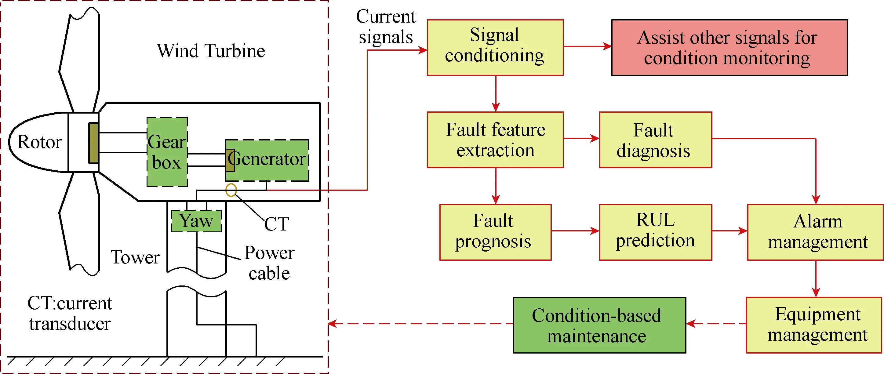
Fig.1 Schematic of the current-based prognostic CMS for wind turbine drivetrains
As discussed in Sections 2 and 3, when the wind turbines operate in varying-speed conditions, and as such the fault characteristic frequencies in current signals are time- varying. Since the current signals used in wind turbine generator control systems are usually sampled at equal time intervals, the fault characteristic frequencies contained in the frequency spectra of the current signals and their amplitudes and frequencies overlap with each other and with the dominant frequencies that are irrelevant to faults. Therefore, it is difficult to extract the nonstationary fault characteristic frequencies directly from the frequency spectra of the current signals or their amplitude or frequency signals.The traditional way to extract nonstationary fault signatures from nonstationary signals is using timefrequency analysis techniques, such as short-term Fourier transform(STFT), wavelet transform, Hilbert-Huang transform[32], etc. However, the frequency resolution of these methods may not be sufficient for wind turbine drivetrain fault diagnosis using generator current signals. Moreover, some of these methods have high computational costs[32]and, therefore, may not be suitable for online condition monitoring.
To solve this problem, several angular or synchronous resampling methods have been proposed to resample a signal with a constant time increment to become a signal with a constant phase increment with respect to a shaft rotating frequency of the wind turbine[30-31,33-34]. As a consequence, the frequency components that are proportional to the shaft rotating frequency, such as the characteristic frequencies of the faults in wind turbine drivetrains, will become constant values in the frequency spectra of the resampled current signals and their amplitude and frequency signals obtained via demodulation. In this way, the energy of fault signatures that distributes over a wide frequency range in the spectrum of the original current signal will concentrate at single locations in the frequency spectrum of the resampled current signal. This will significantly increase the SNR to facilitate fault diagnosis. Therefore,the FFT can be applied directly to generate the frequency spectrum for the resampled current signal or its amplitude or frequency signal, from which the fault characteristic frequencies can be easily identified and extracted.
4.3 Signal conditioning: multiscale filtering
In some circumstances, generator current signals may contain frequencies that are irrelevant to shaft rotating frequencies. For example, the fundamental frequency of the stator current signals of a DFIG is the same as the grid frequency, which is independent of the shaft rotating frequencies of the wind turbine drivetrain.Another example is that generator current signals may contain frequency components caused by tower vibrations, which are non-proportional to the shaft rotating frequencies of wind turbine drivetrains. In these cases, if angular resampling is applied to the current signals, the nonstationary fault characteristic frequencies will become constant values; however, the frequencies that are irrelevant to shaft rotating frequencies will become nonstationary and, therefore, may mask the constant fault characteristic frequencies in the spectra of resampled current signals, leading to a spectrum smearing problem. Therefore, angular/ synchronous resampling is not an effective signal conditioning method in these cases.
To solve the spectrum smearing problem of the current signals containing frequencies that are irrelevant to shaft rotating frequencies, a method based on multiscale filtering spectrum(MFS)[35]was developed. In the MFS method, the instantaneous shaft rotating frequency of the wind turbine is first estimated from a generator current signal. Then, a multiscale filter bank based on a Vold-Kalman filter is designed according to the center frequencies corresponding to the shaft rotating frequency at different scales. The mono-component signals whose frequencies are continuous multipliers of the shaft rotating frequency are subsequently extracted from the envelope of the measured current signal.Finally, a weighted energy spectrum is constructed within the selected frequency range, from which possible fault characteristic frequencies can be identified.
4.4 Fault feature extraction and fault detection
After signal conditioning, the fault signatures are usually extracted from a frequency spectrum, such as the power spectral densit(PSD), of the conditioned current signal. In the PSD, the magnitude at a certain frequency represents the energy of the time-domain signal at the frequency. If the signal has high energy at a certain frequency, it will generate an impulse at that frequency in the PSD spectrum of the signal. An impulse detection algorithm has been proposed to extract the impulses in the PSD spectra of conditioned current signals[30]. If one or multiple extracted impulses are located at fault characteristic frequencies, it indicates the occurrence of faults.
However, some wind turbine drivetrain faults, such as gear defects in gearboxes, cannot be simply detected by investigation of the impulses at the fault characteristic frequencies, because these impulses also occur when the gears have no fault[33]. To solve this problem, statistical features of these impulses[33]and other fault features extracted from original or conditioned current signals, such as noise-to-signal ratio(NSR), root-mean-square(RMS) values, Kurtosis,maximum values, etc. are also used; and fault diagnosis may need to be performed via pattern classification using computational intelligence and machine learning methods[28,36].
4.5 Fault prognosis and RUL prediction
When a defect or fault occurs, it is important to predict the future condition(fault prognosis) and the RUL of the failing component in order to achieve condition-based predictive maintenance. Recently,statistical particle-filtering-based fault prognostic and RUL prediction methods for wind turbine drivetrains have been developed[42-43]. Fig.2 illustrates the schematic of the method proposed in [42]. It consists of four functional modules: signal conditioning, feature extraction, fault prognosis, and RUL prediction. The signal processing methods used in the signal conditioning module have been discussed in Sections 4.1~4.3. The signal conditioning module solves the problems of low SNRs of and nonstationary fault signatures in generator current signals. Then, the PSD of the conditioned current signal is calculated and the fault-related feature is extracted from the PSD spectrum. In the fault prognosis module, an adaptive neuro-fuzzy inference system(ANFIS) model is designed to learn the state transition function of the extracted fault feature. After that, a particle filtering algorithm is designed to predict the fault feature based on the state transition function learned by the ANFIS and the weights of particles. When new data of the fault feature is available, the weights of the particles are updated. Finally, the RUL of failing component is predicted at different time instants, where RUL is the time between now and the moment when the predicted fault feature reaches a threshold, which can be determined using the existing failure database.
4.6 Current-aided vibration monitoring
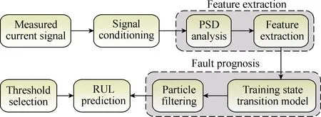
Fig.2 Block diagram of the fault prognostic and RUL prediction method[42]
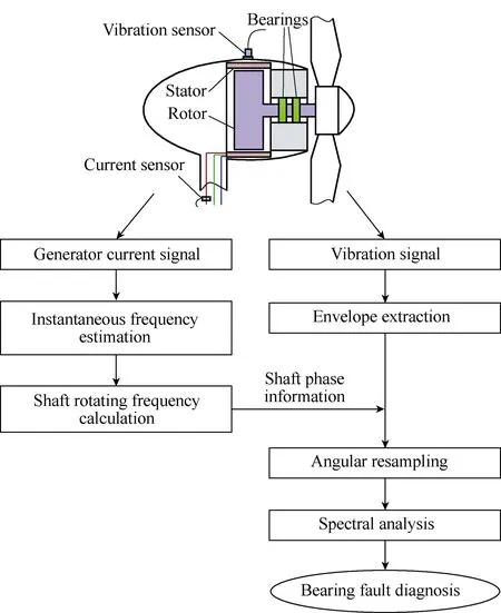
Fig.3 Flowchart of the current-aided vibration order tracking method[31]
Generator current signals have also been used to aid other signals, such as vibration signals, for prognostic condition monitoring of wind turbine drivetrains. A key issue in the vibration monitoring for variable-speed wind turbine drivetrains is the elimination of the effect of the shaft speed variations in the vibration signals measured under varying rotating speed conditions. The work [31]proposed a current-aided vibration order tracking method for bearing fault diagnosis of variable-speed wind turbines, as shown in Fig.3. The method eliminated the need for a rotor position/speed sensor to measure the reference signal for vibration order tracking. A simple and effective algorithm was developed in that work to acquire the reference signal from a generator stator current signal. First, the generator shaft rotating frequency is calculated from the instantaneous fundamental frequency of the current signal, which is estimated by using a time-frequency distribution method.Then, the shaft phase-time relationship is established.With this information, the envelope of the vibration signal that was recorded synchronously with the current signal is resampled with equal phase intervals. Finally,bearing fault diagnosis is performed by observing the impulses at bearing characteristic frequencies in the power spectrum of the resampled vibration envelope signal.
5 Validation results
The generator-current-based prognostic condition monitoring methods have been validated on a variety of laboratory wind turbine drivetrain test rigs, laboratory wind turbines, and field wind turbines of different types and sizes from hundreds of Watts to 1.6MW. Some typical results are presented in the rest of this section to demonstrate the effectiveness and superiority of some of these methods.
5.1 Signal conditioning: demodulation
An Air Breeze wind turbine with a failed bearing was tested. The turbine rotor is connected to the rotor of the generator(a PMSG) directly without a gearbox. The failed bearing was located between the rotors of the turbine and the PMSG. The PMSG has six pole pairs.The wind turbine operated with a varying shaft rotating speed during the test due to the varying wind speed. One phase stator current of the generator was recorded via a Fluke 80i-110s AC/DC current clamp. The measured current signal was collected by a National Instrument(NI)data acquisition system with a sampling frequency of 10kHz. The failed bearing has a broken cage, as shown in Fig.4 in comparison with the new bearing[27].
Fig.5 shows the power spectrum of the original current signal for the wind turbine with the failed bearing.According to (3), the bearing cage fault characteristic frequencies around the fundamental frequencyf1of the current signal aref1±mfF(m=1,2, ∙∙∙.), wherefFis the bearing cage fault characteristic frequency in vibration.Bothf1andfFvary in proportion with the shaft rotating frequency of the wind turbine. Due to the high magnitude of the stator current fundamental frequency component and the varying shaft rotating frequency, the impulses generated by the bearing fault are totally masked by the stator current fundamental frequency component in the power spectrum of the original current signal and, therefore, cannot be identified for fault diagnosis.
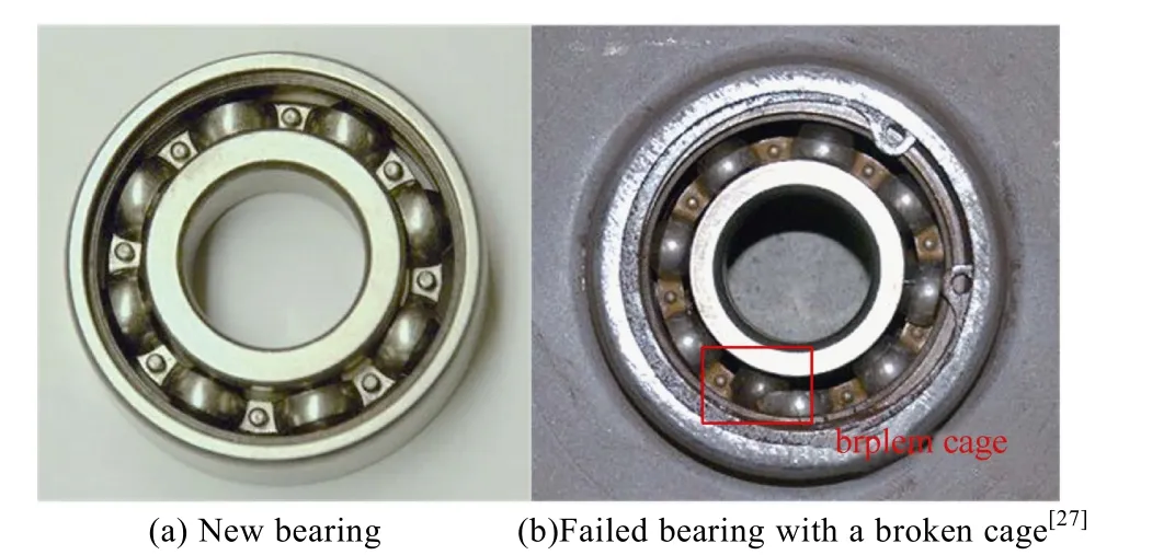
Fig.4 Test bearing
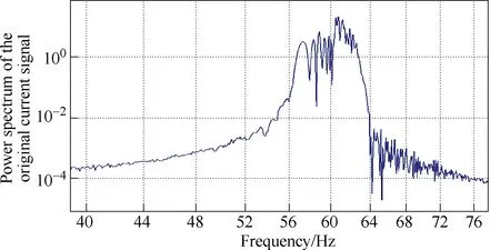
Fig.5 Power spectrum of the original generatorstator current signal
To solve this problem, demodulation is performed for the current signal. Fig.6 shows the power spectrum of the current frequency demodulated signal. The characteristic frequencies of the bearing cage fault distribute over a wide frequency range due to the varying shaft rotating frequency and can barely be identified in the power spectrum. Thus, it is difficult to detect the broken bearing cage fault because the magnitudes of the impulses at the fault characteristic frequencies are too small.
5.2 Signal conditioning: angular/synchronous resampling
To further solve the problem of nonstationary fault characteristic frequencies, angular/synchronous resampling is applied to the current frequency and amplitude demodulated signals. In the resampling process, the varying shaft rotating frequency of the wind turbine was converted to a constant value of 10Hz.Figs.7 and 8 compare the power spectra of the resampled current frequency and amplitude demodulated signals,respectively, for the healthy bearing case and the bearing cage fault case[27]. In the healthy bearing case, no impulse appears in the range from 2Hz to 9Hz in Fig.7(a)or 8(a). However, an impulse appears at 3.95Hz in the power spectra of the demodulated signals in the bearing cage fault case, as shown in Figs.7(b) and 8(b). This impulse frequency is almost the same as the calculated characteristic frequency of the bearing cage fault with the shaft rotating frequencyfrat 10Hz. In addition, the 3.95Hz bearing fault characteristic frequency and the shaft rotating frequency modulate with each other and generate an impulse at 6.05Hz(=10Hz–3.95Hz), as shown in Figs.7(b) and 8(b). The impulses at 3.95Hz and 6.05Hz clearly indicate the occurrence of the bearing cage fault.
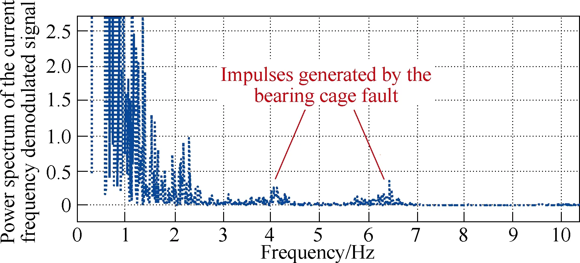
Fig.6 Power spectrum of the current frequency demodulated signal
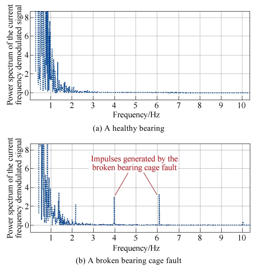
Fig.7 Comparison of the power spectra of the current frequency demodulated signals for the wind turbine with different bearing
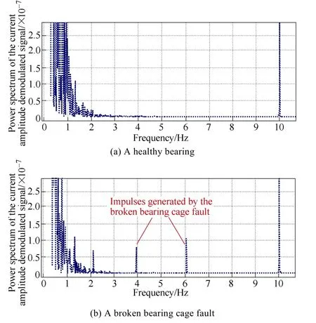
Fig.8 Comparison of the power spectra of the current amplitude demodulated signals for the wind turbine with different bearing
5.3 Signal conditioning: multiscale filtering
To validate the MFS method, a Skystream 3.7 wind turbine in the field was tested[35]. One phase stator current signal of the PMSG of the wind turbine was measured and sampled at 1000Hz. The number of pole pairs of the PMSG is 21. The type of shaft bearings is 6209. Both the MFS method and angular resampling method are applied to the envelope of the current signal.Fig.9(a) and (b) show the order spectra of the current envelope signal obtained by using the angular resampling method and the MFS method, respectively.The cage fault characteristic order of the shaft bearings,OFTFI= 0.598, appears clearly on both plots, indicating that one of the shaft bearings installed in the wind turbine has a cage fault. However, the order spectrum obtained from the angular resampling method contains some interfering peaks around order 15 (marked by an ellipse). These components are those with the frequencies unrelated to the shaft rotating frequency contained in the original current signal. Since they may smear the harmonics of other possible characteristic orders, it is not clear whether or not the bearing has other faults. In Fig.9(b), the interfering peaks disappear by using the MFS method. There are no other components except for the component related to the bearing cage fault relative to the inner ring in Fig.9(b), indicating that only a cage fault has occurred in the bearing. The results prove that the MFS method is superior to the angular resampling method for signal conditioning when the current signal contains frequencies that are irrelevant to the shaft rotating frequency.
5.4 Fault prognosis and RUL prediction
The fault prognosis and RUL prediction method was validated by a gearbox run-to-failure test on a wind turbine drivetrain test rig[42]. The test rig used a two-stage helical gearbox connected with a generator to emulate the drivetrain of a wind turbine. The gearbox was driven by an adjustable-speed induction motor drive through a speed reducer, which were used to emulate the aerodynamics of a wind turbine rotor. One phase stator current of the PMSG was measured by a FLUKE 80I-11s current probe. The current signal was acquired using a NI data acquisition system with an interval of 6 minutes during the entire test. In each 6-minute interval,the data was recorded for 120 seconds.
The NSR defined as follows is used as the fault feature for the fault prognosis and RUL prediction.
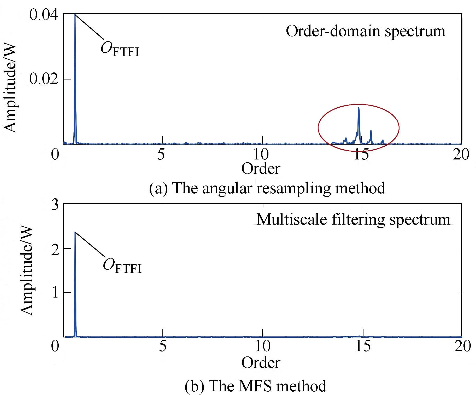
Fig.9 Order spectra of the current envelope signal of the field wind turbine with a bearing cage fault obtained by different methods

wherePsignal(=is the power of the fundamental frequency component (i.e., the amplitude at the fundamental frequency of the PSD spectrum) of the current signal;Pnoise=Ptotal-Psignal; andPtotalis the total power of the current signal defined as:

whereNsis the total number of data samples in the recorded stator current signali(n).
When a fault is developing in the gearbox, the vibration and sound of the test rig will increase. The increased vibration will lead to an increase of the value of the fault feature NSR. At the end of the test, multiple failures have occurred in the gearbox; both the vibration and sound of the test rig reached high levels; and the NSR has exceeded the threshold. The system was shut down due to the safety concerns. A total of 285 120-second data records were obtained in the test. Thus, the lifetime of the gearbox was 285×6 = 1710 minutes.
The values of the fault feature predicted by the particle filtering algorithm are compared with the actual values in Fig.10. The uncertainty envelope is defined to be the curves of the maximum and minimum values of the NSR predicted by the particles in the particle filtering algorithm. In the algorithm implementation, the data before 1200 min are used for training the ANFIS to learn the state transition function and the fault prognosis starts at 1200 minutes. The particle filtering algorithm accurately predicts the trend of the gearbox degradation(i.e., the change of the fault feature NSR).
Fig.11 compares the probability density functions(PDFs) of the RUL predicted by the particle filtering algorithm at 900minutes, 1200minutes, and 1500minutes,where the peaks of the PDF curves indicate the highest probabilities of the predicted failure time[42]. At 900minutes, it is difficult to find the peak value of the PDF. As time goes on, more particles predict the RUL close to the peak value of the PDF, indicating that the RUL prediction becomes more accurate. The peak of the PDF predicted at 1500minutes is close to 1710minutes,which is the actual failure time of the gearbox. This indicates that the particle filtering algorithm has the ability to use new values of the NSR to improve the accuracy of the gearbox RUL prediction as time goes on.Moreover, the RUL can be predicted accurately ahead of time such that maintenance can be scheduled in advance with the optimal logistics to minimize the cost.
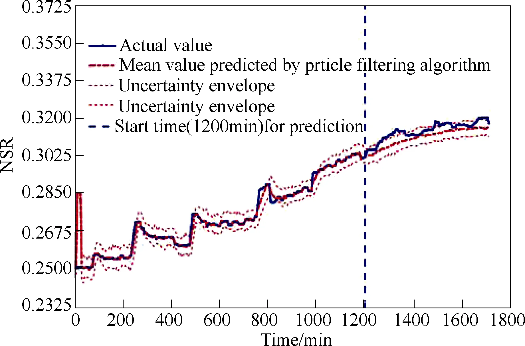
Fig.10 NSR prediction result of the test gearbox
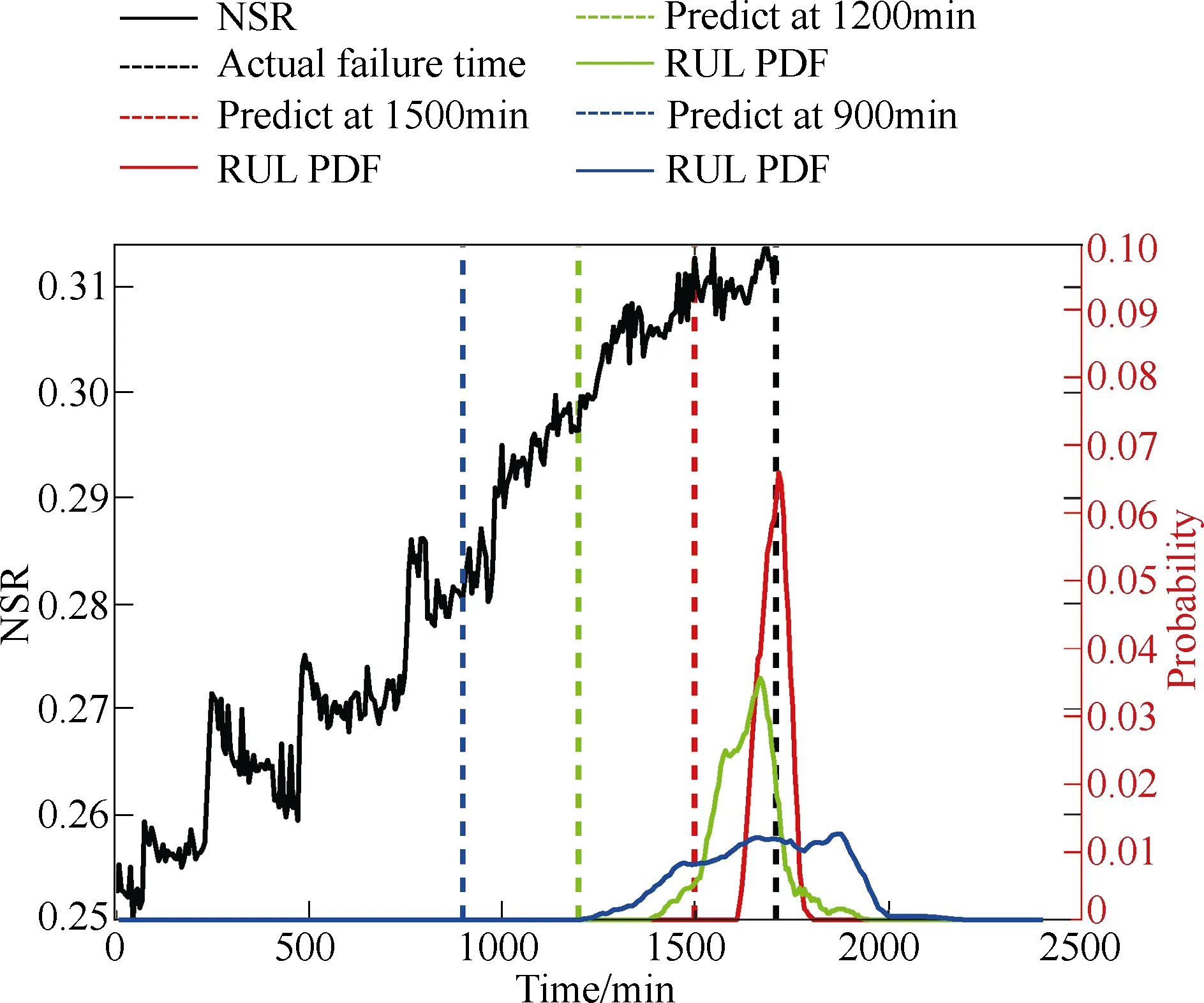
Fig.11 PDFs of the RUL predicted by the particle filtering algorithm at three different time instants[42]
6 Conclusion and recommendations
This paper discussed the principles and challenges of using generator current signals for prognostic condition monitoring of wind turbine drivetrains. A prognostic CMS that incorporated recent advancements in current-based wind turbine fault diagnosis and prognosis and RUL prediction methods was presented.These current-based prognostic condition monitoring methods have been validated on a variety of laboratory wind turbine drivetrain test rigs, laboratory wind turbines, and field wind turbines of different types and sizes from hundreds of Watts to 1.6MW. Some typical results were presented in the paper to demonstrate the effectiveness and superiority of some of these methods for fault diagnosis and prognosis and RUL prediction of wind turbines drivetrains under nonstationary operating conditions.
The current-based prognostic condition monitoring techniques provide a low-cost, reliable solution for the wind industry to reduce the failure rate and level,maintenance costs, and downtime; improve reliability;and extend the life of wind turbines. With further development and field test validations, the current-based prognostic condition monitoring techniques can be implemented in the CMSs of various types of wind turbines.
In addition to wind turbine drivetrains, other wind turbine subsystems, such as power electronic converters,are also subject to significant failures and cause significant downtime of wind turbines. Since the failure mechanisms of the electrical subsystems are different from those of the mechanical drivetrains, additional research effort is needed to develop dedicated prognostic condition monitoring technologies for electrical subsystems of wind turbines. Moreover, since the total number of installed wind turbines is huge, it is beneficial to extend the prognostic condition monitoring from single wind turbines to multiple wind turbines via remote sensing and data acquisition. New technologies need to be developed to improve fault diagnostic and prognostic accuracy and reliability using big data collected from many wind turbines.
 Chinese Journal of Electrical Engineering2018年3期
- Chinese Journal of Electrical Engineering的其它文章
- A Review of Data-Driven Prognostic for IGBT Remaining Useful Life
- Thorough Validation of a Rotor Fault Diagnosis Methodology in Laboratory and Field Soft-Started Induction Motors
- Design, Implementation and Performance of Synchronous Current Regulators for AC Drives
- Circuit Implementation of Power Converter for High-Speed Switching Operations
- Study of the Characteristics and Suppression of EMI of Inverter with SiC and Si Devices
- Capacitive DC Links in Power Electronic Systems-Reliability and Circuit Design
