A Comprehensive Survey on Fault Diagnosis and Fault Tolerance of DC-DC Converters
*,
(1. CISE - Electromechatronic Systems Research Centre, Universidade da Beira Interior, Calçada Fonte do Lameiro, P – 6201-001 Covilhã, Portugal;2. Department of Electromechanical Engineering, Universidade da Beira Interior, Calçada Fonte do Lameiro,P – 6201-001 Covilhã, Portugal)
Abstract: DC-DC converters are becoming more commonly used in power conversion solutions for energy management purposes, being employed in an ever-increasing range of DC-based applications,such as LED lighting, electric vehicles, energy storage solutions, and consumer electronics (laptops,smartphones, etc.). In this context, efficiency and reliability are critical. The research efforts made in improving reliability of DC-DC converters are still quite narrow and scattered. Moreover, DC-DC converters take the shape of an endless number of topologies, with different functionalities and operation principles, thus complicating the task of improving reliability of all forms of DC-DC converters. Consequently, compiling the information about the main failure modes, corresponding fault diagnostic algorithms and fault tolerance strategies developed so far, in a single document, becomes increasingly necessary. Accordingly, this paper presents an up-to-date review of the recent achievements attained regarding the improvement of availability and reliability of DC-DC converters.
Keywords: DC-DC converters, fault diagnosis, fault tolerance, reliability.
1 Introduction
As with any other energy conversion system based on power electronics, DC-DC converters are continuously subjected to a plethora of stress factors, such as electrical, thermal and physical stress. The conjunction of all these stress factors leads to potential early degradation of the converter components, thus limiting the overall useful lifetime of DC-DC converters. Within DC-DC converters, power semiconductors and in particular power switches (IGBTs, MOSFETs), constitute the more susceptible components showing higher failure rates. This explains why recent reliability studies addressing DC-DC converters concentrate efforts on finding new solutions for the diagnostic and prognostic of faults in power switches.
Accordingly, this paper presents the most relevant advancements achieved so far concerning the development of fault diagnostic algorithms and fault tolerance strategies suitable for DC-DC converters.Special emphasis is given in this paper to the diagnostic techniques focusing on the occurrence of open-circuit(OC) and short-circuit(SC) faults in the converters’power switches and/or gate drivers. Furthermore, fault tolerant strategies enabling the continuous operation of the converters, even under power switches fault scenarios, are detailed.
2 Fault diagnostic algorithms
Most fault diagnostic techniques currently available in literature suitable for DC-DC converters, focus on the diagnostic of OC and SC faults in converter power switches. To diagnose switch faults, the algorithms commonly rely on the analysis of converter variables,such as the input current or the DC-bus capacitor voltage.These variables are commonly referred to as diagnostic variables.
OC faults often derive from failures in the gate drivers, soldering break or wire lifting[1]. In a wide group of DC-DC converter topologies, OC faults do not pose a serious threat to the converter core components that remain healthy and the energy transfer to the load is commonly sustained under degraded conditions (more ripple, lower conversion efficiency,etc.). Still, if such faults remain undetected for long periods of time, further damage might be incurred in the converter and, in extreme cases, lead to a total standstill.Therefore, the detection and identification of such failures is critical in preventing further critical damage inside the power converter.
Concurrently, SC faults in the converter switches are severe fault events that must be detected and isolated within a few microseconds. Many fault diagnostic algorithms simply dismiss any capabilities for diagnosing of SC faults. Many arguments are presented for not considering SC faults in the diagnostic of switch faults:
(1) Typically, SC faults are isolated from the rest of the converter circuit resorting to hardware protection devices, namely fuses, and usually result in a very limited, or sometimes, impossible operation of the converter.
(2) SC faults are commonly followed by OC faults,as a result of isolation actions carried out via hardware.
(3) SC faults require a fast response of the control structure, in order to isolate the fault and avoid extended damages in the converter or any other equipment connected to it. Generally, software protection does not provide the ultra-fast response required to overcome the effects of SC faults.
The diagnosis of power switch faults in DC-DC converters is usually performed online and takes place in two distinctive stages: fault detection and fault identification. At the fault detection stage, a fault alarm is triggered; the faulty component and corresponding fault mode remain unknown. During the fault identification stage, the fault mode and the component that has given rise to the fault alarm are identified.Certain fault diagnostic algorithms combine the detection and identification actions in a single stage,meaning that fault detection and identification actions are developed concurrently. Such practice depends on the capabilities of the adopted fault diagnostic algorithm and on the selected fault diagnostic variables.
There is not a unique, generally adopted,classification scheme of the fault diagnostic algorithms developed so far, aimed at semiconductor faults.Nevertheless, it is possible to establish a classification scheme for the fault diagnostic algorithms by taking into account the information required to implement the algorithm. Fig.1 shows a simplified classification scheme.
Most fault diagnostic algorithms aimed at DC-DC converters obtain fault signatures based on certain variables of the converter, sensed in real time. In this paper, these algorithms are categorized as ‘signal processing based algorithms’, since the diagnostic action is solely supported by the analysis of fault signatures,extracted from converter variables whose evolution is perturbed by faults in the converter power switches.
More recently, alternative diagnostic algorithms,with improved robustness against false fault alarms,have been introduced. These algorithms are referred to as ‘model-based algorithms’, since the diagnostic action is supported by a pre-established converter model. The following sections provide deeper insight about each of the aforementioned categories.
2.1 Signal processing based fault diagnostic algorithms

Fig.1 Classification of the semiconductor fault diagnostic algorithms aimed at DC-DC converters
Currently, fault diagnostic algorithms based on signal processing techniques represent the largest share of algorithms available in the literature, aimed at diagnosing power switches faults in DC-DC converters.These algorithms identify certain fault signatures resorting to an analysis of carefully selected converter variables, commonly used for control purposes, as for instance DC-bus current or capacitors voltage. As illustrated in Fig.2, either the converter input, output or internal variables are sensed and subjected to signal processing techniques. The adopted signal processing techniques for diagnostic purposes are highly dependent on the selected diagnostic variables.
The success of these fault diagnostic algorithms achieved so far is mainly a result of the simplicity, the reduced computational effort required to implement the algorithms and by the adoption of black-box approaches.Furthermore, depending on the capabilities of the fault diagnostic algorithm, there is the possibility of implementation of the same algorithm in several DC-DC converter topologies. Therefore, a quite straightforward analysis is adopted, especially when there is no previous knowledge about the converter parameters. The adoption of a black-box approach, typical of signal processing based algorithms, provides the interesting attribute of obviating the need for detailed knowledge of the DC-DC converter parameters. Unfortunately, the action of signal processing based diagnostic algorithms might not be totally effective, since false fault alarms might be triggered when the converter is required to operate under a highly dynamic operational pattern with significant oscillations in the load levels, switching frequencies or conduction modes, leading to inaccurate diagnostic results.
As shown in Fig.1, it is possible to establish a thinner classification of signal processing based diagnostic algorithms, by taking into account whether the diagnostic variables are evaluated in the time or frequency domains.
2.1.1 Time domain signal processing based algorithms
As the name itself suggests, these algorithms implement an analysis, in the time domain, of the variables selected for diagnostic purposes. Such analysis may rely on a variety of methodologies, including magnitude analysis, trend analysis, limit evaluation,mean values assessment, statistical moments, etc.
Certain fault diagnostic algorithms based on time-domain analyses are designed to meet very specific requirements of some converter topologies or operating points. Therefore, the extrapolation of those algorithms to other converter topologies might be quite challenging or even impossible. In opposition, there are certain fault diagnostic algorithms based on time-domain analyses which, by virtue of their characteristics, provide a broad spectrum of action, allowing the proper extrapolation to several converter topologies. It is the case of algorithms based on converter variables present in most converter topologies, for example the DC-bus current.

Fig.2 Principles of implementation of a signal processing based fault diagnostic algorithm aimed at DC-DC converters
The wide range of fault diagnostic algorithms based on a time-domain analysis differs mainly on the selected diagnostic variables and on the methodologies used to extract relevant fault signatures. The requirement of thresholds for the decision-making process also depends on the architecture of the diagnostic algorithm. Often,gating signals complement the information provided by the diagnostic variables, allowing for easy location of the faulty component. While selecting diagnostic variables, researchers look forward to selecting diagnostic variables which fulfil the following requirements: 1) The requirement of additional sensors is obviated or, at least, reduced; and 2) Several fault signatures are provided by that diagnostic variable, allowing for proper identification of several fault modes or faulty components.
Older diagnostic tools applying time-domain analyses track anomalous deviations in the magnitude of converter variables using, for instance, statistical moments of the converter voltages and currents[2]or the input current peak to integral ratio[3]to diagnose OC faults in the target converter topologies. The implementation of these algorithms is quite simple and relies on simple analogue circuitry to detect switch faults. Even though the validation of the algorithms is solely confirmed for the cascaded converter[2]and full-bridge(FB) zero voltage switching(ZVS)DC-DC converter[3], the algorithms’ nature enables the implementation of such diagnostic strategies in other converter topologies as well.
In simpler multilevel DC-DC converter assemblies,the DC-bus capacitors voltage balance, a condition which should be continuously met, is monitored to detect switch faults[4]. Despite the simplicity of the algorithm, the simple act of analysis of the DC-bus capacitors voltage does not provide conclusive information, in most situations, about the converter faulty component(s). The implementation of this algorithm on a three-level flying capacitor DC-DC converter comprises the comparison of the flying capacitor voltage with two distinctive thresholds. Based on the results of such comparison, it is possible to issue a fault alarm and, whenever feasible, to identify the faulty component.
When it comes to isolated DC-DC converter topologies, the transformer windings voltages are widely selected as diagnostic variables. The analysis of the windings voltages mean values have been proven suitable to detect and identify switch faults in DC-DC converter topologies employing galvanic isolation[5].The decision process of the algorithm requires the establishment of an empirical threshold. Identical fault diagnostic algorithm, equally based on the transformer primary-side voltage, compares the amplitude of this diagnostic variable to a predefined threshold, allowing detection of the presence of OC faults[6].
The inductor current slope is used as fault diagnostic variable in the diagnostic of power switches faults in non-isolated single-ended converters. The measured inductor current slope sign is compared with the expected inductor current slope sign, resulting in two subsystems which operate concurrently, ensuring fast and reliable diagnostic results[7].
Thereafter, a series of fault diagnostic algorithms,based on the same diagnostic variable and principles of operation have introduced small improvements in the effectiveness of the original fault diagnostic algorithm.One of these algorithms consists of two state machines with a similar structure operating in parallel to realize the fault diagnostic action. This adaptation allows for distinguishing of OC and SC faults, which was not available in the preliminary version of the algorithm[8].
To slightly improve the diagnostic effectiveness,the non-ideal response of the converter is considered in the implementation of another derivation of the original algorithm. The fault diagnostic action compares the sign of the inductor current slope and a delayed version of the gating signal, characteristic of the non-ideal converter[9].
Supported on the same diagnostic principles,simpler strategies, requiring less computational effort,were developed. The observation of the switch health condition, through the analysis of the inductor current slope sign during one switching period, is performed resorting to a single state machine[10,11].
In a preliminary iteration[10], fault diagnosis is achieved, but there are no conclusive results about which fault mode impairs the switch (OC or SC fault),as shown in Fig.3(a). The transition between states,denoted asx1andx2in Fig.3(a), takes into account the information provided by gating signalq, depicted in Fig.3(b). Each transition is triggered by the edges of gating signalq, as depicted in Fig.3(b).
The problem of fault identification verified in the aforementioned algorithm[10]is overtaken by selecting different moments for the transition between machine states[11]. Fig.4(a) depicts a simplification of the flowchart followed by the state machine[11], while Fig.4(b) shows a timeframe which illustrates the moments in which the transitions between most meaningful states take place.
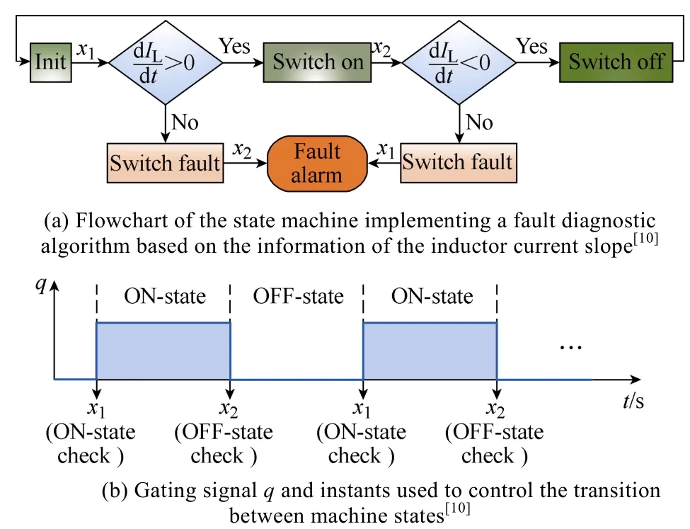
Fig.3 Flowchart and the gating signal of Ref.[10]

Fig.4 Flowchart and the gating signal of Ref.[11]
To obtain optimized diagnostic results, certain fault diagnostic strategies are developed to meet the requirements of practical applications. The low frequency oscillations in the amplitude of PV variables(voltage, current and power) provide suitable information to detect switch faults[12]. A sequence of events,comprising of the increment of the PV panel voltage,and the decrement of the PV panel current and power,reveal the occurrence of OC faults in the converter responsible for the MPPT control[12].
A significant group of fault diagnostic algorithms rely on analysis, in the time domain, of the inductor current amplitude. One of these algorithms suitable for single-switch converters selects strategic instances to sample the inductor current amplitude in order to establish logical relations between the sampled values. A comparison between the absolute values of the inductor current, sampled at three distinctive moments allows for identification of faults in the converter switch[13].
Alternative approaches, based on the same diagnostic variable, take advantage of the gating signals information to sample the amplitude of the inductor current at the rising and falling edges. Variations of the fault diagnostic algorithm were successfully employed in a multi-input DC-DC converter[14], non-isolated bidirectional DC-DC converter[15], non-isolated unidirectional DC-DC converter[16], and in an interleaved DC-DC boost converter[17]. As confirmed in Fig.5, the logical relations between the current amplitude measured at the rising and falling edges of the gating signals are affected by OC faults in the converter switches. Indeed, it is a behaviour observed in all aforementioned converter topologies[14-17].
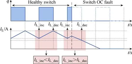
Fig.5 Evolution of the inductor current in a non-isolated unidirectional buck converter, under healthy condition(first half of the switching pattern) and faulty condition(second half of the switching pattern)
Current amplitude also provides sufficient information for diagnostic of faults in parallel-connected single active bridge(SAB) DC-DC converters[18]. The converter output current is sampled at pre-established moments, allowing for detection and even identification of the module containing the faulty switch. The algorithm takes advantage of the fact that the switches’ turnoff moment overlaps with the peak of the converter output current. A single OC fault shrinks one of the peaks of the converter output current[18], as show in Fig.6.
The simple act of evaluating the converter current amplitude might demonstrate ineffective in more complex converter topologies. To meet the requirements of reliable diagnostics in complex converter assemblies,more elaborate fault diagnostic algorithms have been developed. Resorting to the same diagnostic variable(converter input current), a fault diagnostic algorithm based on the current derivative can detect and identify OC faults in interleaved DC-DC converters[19]. In general terms, the algorithm does a comparison between the measured derivative sign and the expected derivative sign, on each interval considered in the analysis. As represented in Fig.7, each switching period comprises 6 identical intervals. In the example provided there, the mismatch in the derivative sign occurs in interval (d) of periodTsw_2.
The voltage measured in any of the magnetic components (inductors or transformers) of a DC-DC converter provides a fault diagnostic solution with wide spectrum of action, allowing the diagnosis of switch faults in a plethora of converter topologies[20]. By cross-checking the information available in the voltage waveform and the gating signal(s) applied to the converter switch(es), it is possible to identify both OC and SC faults in the converter switch(es)[20]. Based on the fault signatures extracted from the magnetic components voltages, an alternative algorithm overrides limitations manifested in the original algorithm, by improving the fault diagnostic capabilities for converters operating in discontinuous conduction mode (DCM)[21].

Fig.6 Parallel-connected SAB converter output current evolution under different conditions

Fig.7 Evolution in time of the three-phase interleaved DC-DC boost converter input current, over two switching periods (Tsw_1 and Tsw_2). Shadowed intervals highlight the differences in the sign of derivative of Iin[19]
Aiming at the diagnosis of SC faults in the primary-side bridge of the phase-shifted full-bridge(PSFB) converter[22], information is extracted from two converter variables: the input current and the transformer primary voltage. A SC fault in the primary-side bridge promotes a significant increment in the input current, far exceeding a predefined threshold, selected empirically[22].To identify which one of those two switches is faulty,the algorithm checks the transformer primary voltage waveform. This observation aims at finding the sign of the transformer primary voltage, as the position of the faulty switch affects its sign.
The diode voltage is adopted as a diagnostic variable in an alternative fault diagnostic algorithm, focused on non-isolated DC-DC converters. The establishment of logical relations between the obtained fault signatures and the converter gating signals enable the diagnostic of OC and SC faults in single-switch non-isolated DC-DC converters, not only in the converter switch, but also in the diode[23]. At least one additional voltage sensor is required to implement the algorithm.
To assess the health state of the switches that compose each submodule of a modular multilevel DC-DC converter, an alternative fault diagnostic algorithm establishes a comparison between the voltage measured at the output of each submodule and the voltage measured at the submodule input[24]. The algorithm is based on a modular architecture, meaning that each submodule of the modular multilevel converter(MMC) must contain all the components required to deploy the algorithm.
To promote the adoption of non-invasive fault diagnostic functions, a Rogowski coil sensor monitors the converter inductor voltage. Two important diagnostic actions are attainable concurrently, based on a single diagnostic variable:1) determine the presence of switch faults in non-isolated single-switch DC-DC converters;and 2) monitor the equivalent series resistance (ESR) of the converter capacitor[25].
Fault diagnosis based on the second-order derivative of the converter has been recently proposed to diagnose switch faults in bidirectional interleaved DC-DC converters[26]. The fault detection is obtained by checking the magnitude of the second-order discrete-time derivative of the converter left-side current in well-defined periods. To identify the faulty switch, the gating signals are used along with the information of the second-order discrete-time derivative to locate the faulty switch[26].
Fault diagnosis based on the analysis of the reference current error provides a distinctive fault diagnostic approach. DC-DC converters commonly rely on current control strategies based on PI controllers. The abnormal increment of the reference current error provides good fault indicators, that enable the detection of power switches faults[27].
2.1.2 Frequency domain signal processing based algorithms
Fault diagnostic algorithms employing signal processing techniques in the frequency domain did not attract much attention from the scientific community involved in topics related to the improvement of reliability of DC-DC converters. The significant computational effort and the large number of training sets required to recognize all switch fault events constitute some of the hurdles for the successful implementation of such diagnostic algorithms.
The magnetic near field of the converter magnetic components (inductors or transformer) is used as a fault diagnostic variable in one of the few examples of algorithms employing spectral analysis for diagnostic of faults in DC-DC converters. The algorithm comprises the extraction of the information from the magnetic near field, through the computation of the Fast Fourier Transform(FFT)[28]. Auxiliary tools, based on neural networks and an accumulator, carry out the spectral analysis required to diagnose faults in the power switches, as depicted in Fig.8.
2.1.3 Performance of the signal processing based algorithms
Table 1 compiles the information considered relevant to obtain a general picture of the performance levels of each fault diagnostic algorithm based on signal processing techniques.
All the information provided in Table 1 is a result of the analysis and compilation of data previously available in the literature.
The maximum diagnostic time (Td_max)consists on the maximum time required to perform the detection and identification tasks. In algorithms that limit their action to the detection of faults,Td_maxsolely reflect the maximum fault detection time.
2.2 Model-based fault diagnostic algorithms
Model-based fault diagnostic algorithms for DC-DC converters became popular in the last few years. As the implementation of these algorithms requires significant computational effort, the emergence of these algorithms was only made possible as a result of the increased processing capabilities of recent generation digital controllers.

Fig.8 Fault diagnostic algorithm based on the spectral analysis of the magnetic near field waveform
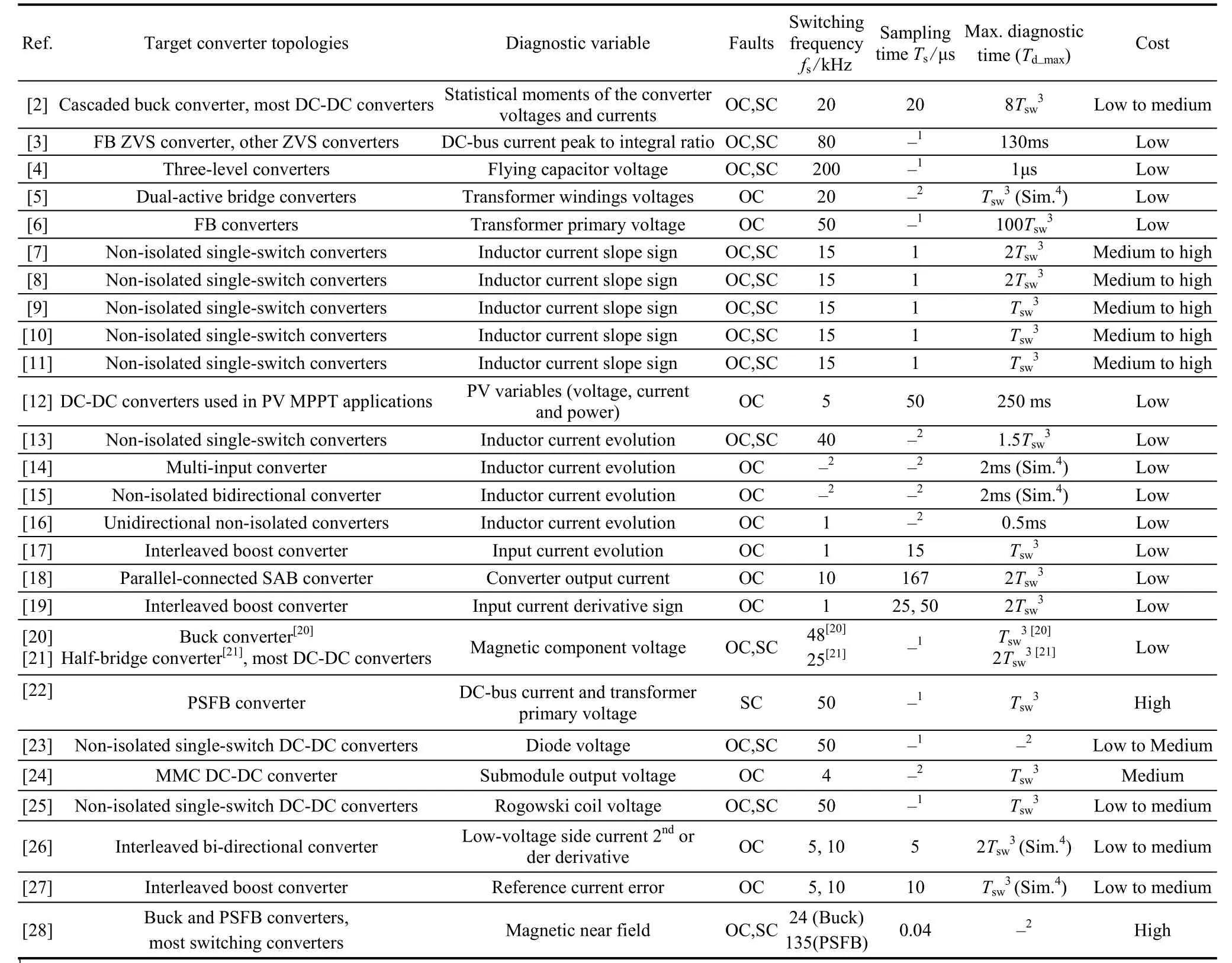
Table 1 Features of signal processing based fault diagnostic algorithms
These algorithms overcome part of the challenges faced by signal processing based algorithms, since mode-based fault diagnostic algorithms feature resiliency and effectiveness while detecting OC and/or SC faults,independently of the DC-DC converter operating conditions (e.g. switching frequency, load level,conduction mode, etc.). The robustness against nonlinearities, such as noise or load transients, is also improved in model-based fault diagnostic algorithms.
To implement model-based fault diagnostic algorithms, a state-space model of the DC-DC converter under study must be established. Previous knowledge of the DC-DC converter parameters (inductances,capacitances, parasitic resistances, etc.) is a premise for the development of most model-based fault diagnostic algorithms.
In general terms, model-based algorithms aim to compare the expected converter response, modelled via analytical methods, with the effectively observed converter response, assessed through the analysis of the converter output signals such as voltage or current, as illustrated in Fig.9. Based on detailed information about the converter parameters, the converter topology and the converter input signals, the converter behaviour is modelled and emulated with a high degree of precision.Residuals are generated by comparing the converter response with the modelled response.

Fig.9 Principles of implementation of a model-based fault diagnostic algorithm aimed at DC-DC converters
Just like in signal processing based algorithms, the treatment of the information provided by residuals may be dealt with by resorting to different strategies. A decision-making procedure, typically based on a careful evaluation in the time domain of the residualγ,allows for extraction of valuable information that give clues about the fault modes perturbing the converter operation. From the analysis of the literature, it is concluded that model-based fault diagnostic algorithms suitable for DC-DC converters mainly differ with regards to the strategies developed to estimate the converter response.
State observers are tools, within the group of model-based fault diagnostic algorithms, commonly adopted to estimate the state of DC-DC converters. The sliding mode observer is one of those tools. To obtain the estimation of the converter state using a sliding mode observer, the mathematical conditions that define the converter model are combined with the observer vectors[29-30]:

Sliding mode observers can be defined to estimate any converter variables, considered suitable for fault diagnostic purposes. Even though sliding mode observers were originally developed for modular multilevel converters (MMCs), they can be also employed in DC-DC converters based on MMCs and related DC-DC converter topologies. Note that,depending on the converter topology and the selected diagnostic variables, this algorithm might not provide enough information to identify the faulty element, as often happens in MMCs[29-30].
Current emulation is one of the most recent strategies used to diagnose power switches faults in DC-DC converters[31-32]. Diagnostic of both OC and SC fault events in the switches of any non-isolated DC-DC converter topology is feasible. It is a fault diagnostic algorithm that establishes a short-term prediction of any desired converter variable, allowing for prompt detection of abnormal deviations for that variable. In addition to the converter parameters, the converter input and output voltages and the inductor current are the required diagnostic variables. The fault diagnostic action takes place in two steps. Faults are detected by comparing the expected inductor current for a momentnand the measured inductor current at that same momentn.The decision process must be supported by a predefined threshold. The direction of the deviation between the measured and the expected inductor current provides relevant information to identify the faulty component. This fault diagnostic algorithm provides an appropriate mean to diagnose switch faults in non-isolated DC-DC converters, allowing it to find those faults in a very short period of time. No additional sensors are required to deploy the algorithm.
Fault diagnosis based on a state estimator[33]demonstrates potential to extend the range of components whose faults are detectable, embracing faults occurring in sensors and passive components. Furthermore, the range of converter topologies compatible with this algorithm is very extensive[33].
During the fault detection stage, the residual of the difference between the measured converter state and the estimated converter state is determined. A detection alarm is triggered if the Euclidean norm of the residual surpasses a predefined fault detection threshold. That threshold is defined empirically, based on a worst-case scenario, where the transients on voltage and current considerably increase the Euclidean norm of the residual.
The fault identification stage is developed separately.It comprises the computation of the inner product between residual and each one of the fault signatures available on a pre-established library.
Note that the model estimator must be executed in real-time, at a very high sampling rate, thus demanding significant computational effort. A fast and powerful DSP platform is therefore required to deploy the algorithm. This fact can be considered the major drawback of the algorithm.
Conversely, the wide applicability, high resilience,and fast response represent the major virtues of this fault diagnostic algorithm.
To better evaluate the performance and merits of the aforementioned model-based fault diagnostic algorithms suitable for DC-DC converters, Table 2 establishes a comparative analysis between the most relevant fault diagnostic algorithms based on the converter models.
Even though the diagnosis of power switches faults represents the majority of the research effort developed so far with regards to the improvement of reliability of DC-DC converters, the literature provides additional model-based algorithms that were developed for alternative purposes. These algorithms are typically employed in the estimation of converter parameters like inductances and capacitances. Still, these algorithms demonstrate potential to carry out fault diagnostic actions in power switches as well. These model-based algorithms also provide a solid framework for the future development of fault prognostic tools. For reference,a small sample of model-based algorithms aiming the estimation of other converter states is provided:algorithms based on Kalman filters[34], self-tuned Kalman filters[35], observers featuring adaptive estimation of parameters[36], or adaptive gradient descent[37].

Table 2 Features of the model-based fault diagnostic algorithms
3 Fault-tolerant strategies
Fault diagnosis assumes a major importance while ensuring high reliability standards for DC-DC converters.Still, fault diagnostic actions do not allow, by themselves,to smooth the negative effects of faults in those converters. Implementation of fault-tolerant strategies on faulty DC-DC converters enables the continuous power conversion function, with acceptable quality levels, along the post-fault period.
Naturally, the adoption of fault-tolerant strategies does not allow, in most cases, to fully recover the power conversion capabilities of a DC-DC converter. Power quality degradation and de-rating of the power transferred to the load are commonly observed, even after the reconfiguration of the faulty DC-DC converter takes place. Side effects should be expected as a result of the implementation of the reconfiguration strategies. Higher conduction and switching losses are two good examples of the side effects that are commonly experienced during the post-fault operation of a fault-tolerant converter.
Generally, the deployment of fault-tolerant strategies implies the adaptation of the converter control strategy.The implementation of fault-tolerant strategies might be also supported by additional hardware. Based on the conditions required to implement each fault-tolerant strategy, it is possible to establish classification criteria for the fault-tolerant strategies available in the literature,as stated in Fig.10.
3.1 Reconfiguration strategies free of additional hardware
Literature provides a fairly reasonable set of DC-DC power conversion solutions which take advantage of the inherently fault-tolerant architecture of some converter topologies to maintain the power conversion function during the post-fault period, without resorting to any additional hardware. Most common strategies free of additional hardware are based on two distinctive approaches: phase-shift adjustment and bypass of the faulty module(s).
3.1.1 Phase-shift adjustment
Fault-tolerant control strategies based on phaseshift adjustment introduce changes in the modulation of the gating signals applied to the faulty converter. This reconfiguration measure implies the adjustment of the phase-shift between the control signals applied to the healthy converter switches/modules (Fig.11).
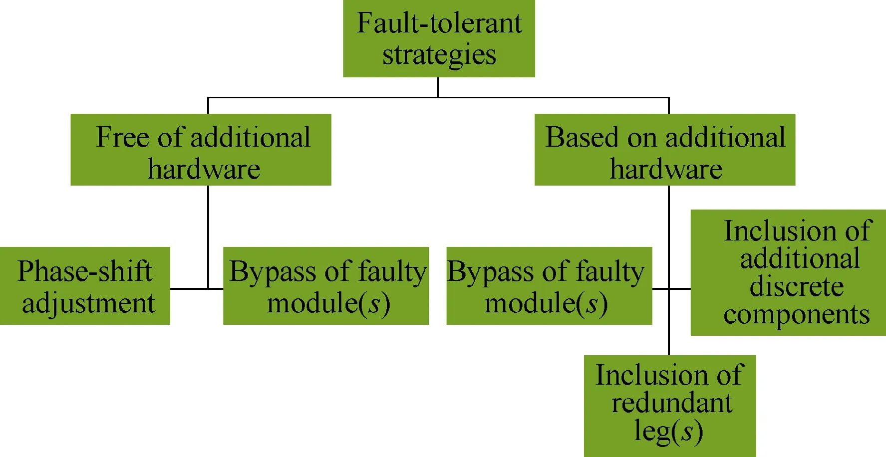
Fig.10 Classification of the fault-tolerant strategies,aimed at DC-DC converters, available in the literature
After identifying a fault which impairs the switch controlled by signalq1, the gating signal related to the faulty switch is eliminated from the switching pattern. In parallel, the phase-shift between gating signals applied to the healthy switches is corrected, taking into account the number of switches which remain intact. In the example shown in Fig.11, gating signalsq2andq3are shifted by π rad between each other, aftert= 0.55ms.
By adopting this reconfiguration strategy, the symmetry of the interleaved switching pattern is re-established for the post-fault period.
Phase-shift adjustment is a reconfiguration measure commonly adopted in converter topologies that employ a phase-shift modulation strategy. Therefore, phase-shift adjustment provides fairly good results not only on multiphase converters, also known as interleaved DC-DC converters[17,19,38-41], but also on parallel-connected SAB DC-DC converters[18]or input-parallel output-series(IPOS) converters[42].
Simplicity, low or null implementation cost, and effectiveness are the major benefits of this fault-tolerant control strategy. Nonetheless, a lower power conversion efficiency ratio should be expected, as a result of the implementation of this fault-tolerant strategy.
3.1.2 Bypass of faulty module(s)
Albeit uncommon, the implementation of bypass functions may take place in a very simplified manner in certain modular multilevel converter topologies.
The original structure of the converter includes all the components required to perform the bypass function.It is the case of the multilevel DC-DC converter depicted in Fig.12.
The implementation of the reconfiguration strategy is restricted to the adaptation in the control of the switches of the bypassed module.

Fig.11 Evolution of a typical interleaved switching pattern after an OC fault, occurring at t = 0.55ms

Fig.12 Fault-tolerant bidirectional modular multilevel converter[43-44]
Bypassing the faulty module(s) of a modular DCDC converter topology presents some advantages over identical reconfiguration strategies: 1) the implementation cost is null; and 2) the transition to the fault-tolerant control strategy does not imply relevant changes in the original control scheme. Unfortunately, the power conversion capabilities suffer a considerable depreciation for the post-fault period.
3.2 Reconfiguration strategies employing additional hardware
The category of reconfiguration strategies employing additional hardware encompasses most reconfiguration strategies available in the literature. Additional components are introduced in the original converter architecture, following a configuration which aims to partially recover the power conversion capabilities lost as a result of OC and/or SC faults. Typically, the inclusion of additional components aims to either bypass the faulty element, if the converter has a modular architecture, or to directly replace that element. Such replacement can take place at the device level (e.g.single TRIACs, IGBTs, MOSFETs, etc.), or at the leg level (e.g. redundant half-bridge, etc.), depending on the DC-DC converter topology.
3.2.1 Bypass of faulty module(s)
In DC-DC converter topologies with modular structure whose original architecture does not provide enough elements to develop bypass functions, it becomes necessary to introduce additional discrete components, aiming to obtain fault tolerance capabilities.It is the case of the input-series output-parallel (ISOP)converter[45-46], where the faulty module is bypassed resorting to additional components, such as thyristors or solid-state relays (SSRs), following the configuration shown in Fig.13. Each module represents any simpler DC-DC converter topology.
Fault tolerance based on bypass of faulty modules is equally feasible on cascaded DC-DC converters[47]. Due to the cascaded configuration, a single switch fault may compromise the power conversion function of the entire converter. Under such circumstances, the isolation and bypass functions assume major importance. To obtain the isolation and bypass of the potential faulty module(s), a significant number of additional power switches must be included in the fault-tolerant cascaded DC-DC converter.

Fig.13 Fault-tolerant ISOP converter[45-46](Shaded areas delimited by dashed lines highlight the bypass switches,denoted as Q1, Q2, and Qn)
3.2.2 Inclusion of additional discrete components
Fault-tolerant converter architectures based on additional discrete components often employ components that are different from the ones used in the original DC-DC converter topology.
The additional discrete components introduced in fault-tolerant converters do not necessarily aim to directly replace the functions of the faulty switch(es). In FB DC-DC converters, the reduction of the converter output voltage is the most relevant side effect arising from OC faults in the switches of the transformer primary-side bridge. Therefore, reconfiguration strategies suitable for FB DC-DC converters aim to compensate the decay in the output voltage. One of those faulttolerant architectures requires an additional redundant transformer winding, placed in the transformer secondary winding[6], following the configuration shown in Fig.14.The auxiliary winding is activated once a faulty switch impairs the operation of the transformer primary-side bridge.
The insertion of an auxiliary transformer winding as a means to compensate the reduction of the converter output voltage involves a fairly high implementation cost. Alternative reconfiguration strategies provide feasible and cheaper solutions to the same problem. To recover the pre-fault voltage level at the converter output, a simple boost converter is connected, in a cascaded configuration, in either the transformer primary-side[48]or the transformer secondary-side[49]. A third alternative reconfiguration strategy also provides a solution for the voltage decay problem in FB and multilevel series- resonant DC-DC converters. Two capacitors and two power switches are added to the FB rectifier connected in the transformer secondary-side,thus obtaining a voltage doubler configuration[50-51].
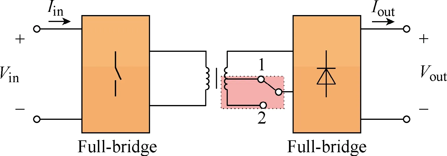
Fig.14 Fault-tolerant FB DC-DC converter based on an auxiliary winding in the transformer secondary winding[6]
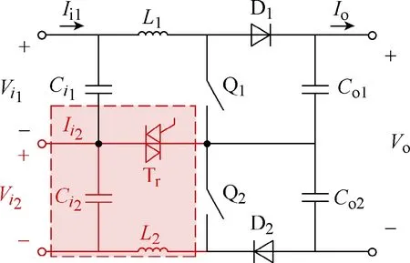
Fig.15 Fault-tolerant non-isolated three-level DC-DC converter[12](Additional components introduced in the fault-tolerant converter architecture are highlighted in red)
In most multilevel DC-DC converters and,particularly, in the non-isolated three-level DC-DC converter, a single OC fault dictates the complete loss of power conversion capabilities. The fault-tolerant architecture of a non-isolated three-level DC-DC converter, depicted in Fig.15, consists of a rearrangement of the converter input. One TRIAC and two additional passive components are displaced in a manner that allows for accommodating multiple voltage sources,connected in series, at the input of the multilevel converter[12]. Despite the partial loss of power conversion capability, the extension of the converter operation is ensured with this fault-tolerant architecture[12].
Due to the lack of redundancy of the single-switch buck converter, a single OC fault completely shuts down the converter operation. To solve the problem, a fault-tolerant architecture of a buck converter is derived from the equivalent circuit of two distinctive DC-DC converter topologies[52]. Operation at either buck or buck/boost mode is feasible while adopting the faulttolerant architecture. In comparison to the traditional buck converter, the fault-tolerant buck converter includes one additional power switch[52].
3.2.3 Inclusion of redundant legs
Fault-tolerant architectures based on redundant legs perform a direct replacement of the faulty switch(es).Typically, those redundant legs consist of redundant switch(es) and, whenever applicable, other auxiliary components.
The fault-tolerant architecture of a single-switch DC-DC boost converter[8,11]represents a good example of a fault-tolerant architecture based on redundant legs.The redundant leg, composed of one switch and one TRIAC[8], or just one switch[11], is placed in parallel with the original converter switch. If the original converter switch becomes faulty, the redundant leg is activated.This reconfiguration strategy only becomes an interesting and cost-effective solution when employed in more elaborate converter assemblies, composed of an association of several single-switch boost DC-DC converters[8,11], as depicted in Fig.16. In that case, a single redundant leg effectively replaces a faulty switch in any of the converters.
3.3 Comparative analysis of the converter reconfiguration strategies
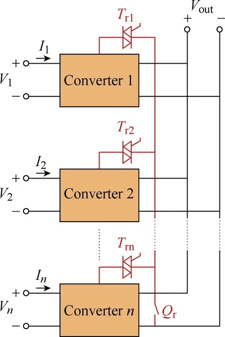
Fig.16 Implementation of a redundant converter leg based on a single redundant switch (Qr)[8,11]
Table 3 summarises the features of the most relevant fault-tolerant strategies suitable for DC-DC converters. Special attention should be devoted to the column ‘Control reconfiguration?’. It is considered that a reconfiguration of the converter control is conducted when the control strategy of the healthy converter switches, legs, or modules is adapted for the post-fault operation. Changes in the control of switches that aim to isolate faulty modules are not categorized as control reconfiguration. The consideration of implementation cost takes into account the assessment of the number of additional components required to develop the fault- tolerant strategy.
Also note that the reconfiguration strategies that obviate the requirement of additional hardware do not imply any additional cost, and as such the criterion‘Cost’ is categorized as ‘Not applicable’ in Table 3.
4 Conclusions
Fault diagnosis and fault tolerance in DC-DC converters have attracted much attention in the last few years. The compelling need for highly reliable and efficient power conversion solutions, suitable to support the tasks of energy management on the wide range of DC-based applications, has triggered the development of new solutions for the diagnostic of faults and reconfiguration of faulty DC-DC converters.
The solutions available in literature provide effective fault diagnostic and fault-tolerant solutions for part of the wide range of DC-DC converter topologies and their typical end-users, allowing them to establish a solid framework for the development of reliable energy management solutions suitable for DC-based applications.Still, further developments are foreseen in this highly dynamic research topic in the near future.

Table 3 Features of the fault-tolerant strategies
 Chinese Journal of Electrical Engineering2018年3期
- Chinese Journal of Electrical Engineering的其它文章
- Prognostic Condition Monitoring for Wind Turbine Drivetrains via Generator Current Analysis
- A Review of Data-Driven Prognostic for IGBT Remaining Useful Life
- Thorough Validation of a Rotor Fault Diagnosis Methodology in Laboratory and Field Soft-Started Induction Motors
- Design, Implementation and Performance of Synchronous Current Regulators for AC Drives
- Circuit Implementation of Power Converter for High-Speed Switching Operations
- Study of the Characteristics and Suppression of EMI of Inverter with SiC and Si Devices
