
Structural Design and Performance Analysis of a Deep-Water Ball Joint Seal
2018-10-11 03:31:54YongjunHouQianTangZhixingWuXiaomingLiu
Yongjun Hou·Qian Tang·Zhixing Wu·Xiaoming Liu
Abstract
Keywords Deep-water drilling . Ball joint . Spherical seal . Nonlinear theory . Finite element technique . Sealing performance
1 Introduction
In deep-water drilling apparatus,the ball joint is a device developed in recent years to replace flexible connectors and is an indispensable device when connected to a riser(Fowler and Gardner 1980;Kozik et al.1990;Tan et al.2013).The internal conduit has access to high-pressure or ultra-high pressure drilling fluid.If this drilling fluid leaks out when the spherical joint rotates,it can lead to pollution of the marine environment and/or irretrievable safety incidents;therefore,the ball joint must be safe and reliable in its structural design and exhibit extraordinary sealing performance.
The ball joint seal is a type of spherical seal, and international research on this topic is mainly concentrated in the fields of bearings and automobiles;references to lower ball joint seals are rather rare.Hanes(1969),Zuthem et al.(2000),and Shi(2006)proposed a traditional spherical seal as a packing seal;however,this is not suitable for deep-water drilling because as it easily leaks under high fluid pressures.Watkins et al.(1976)used bellows technology to seal a spherical joint. One end of the bellows was welded to the inner wall of the ball and the other welded to the inner wall of the lower conduit. The drilling liquid and seawater were cut off using the bellows.However,the bellows easily eroded under the scour of sediment from the drilling fluid and once this was damaged,the whole ball joint had to be replaced,increasing the maintenance costs.Moog(2003)adopted a flexible part formed by stacking rubber and steel.In the manufacturing process,the ball,the flexible part,and the shell were made as a whole,which fulfills the function of deflecting the ball and also prevents drilling fluid leaking from the spherical surface.However,rubber in a lowtemperature environment is prone to fatigue damage and if even sight leakage occurs the seal must be totally replaced,leading to high maintenance costs.Feng et al.(2006)proposed a spherical seal technique where two metal spherical surfaces fit tightly to seal the ball joint.This technique requires highprecision machining and high manufacturing costs,and the whole thing needs to be replaced if leakage occurs,raising the maintenance costs.Moses et al.(2008)proposed a technique for a ball joint seal using a combination of bellows and a flexible body.The sealing method at the spherical surface is as the same as in Moog’s technique,except a different material was used for the flexible body.Song et al.(2009)adopted acrylonitrile butadiene rubber for a spherical seal,but it cannot be used at low temperatures and has poor elasticity.Wan(2014)devised a method using metal-plated ceramics;however,ceramics are brittle and fragile and can only be used in shallowwater drilling,and the ball joint must be totally replaced when leakage occurs.Povloski and Duy(2014)improved the structure of the ball joint for a better sealing effect,but still used a flexible body similar toMoog’s, which does not meet the working conditions of low temperatures and high pressures.To summarize,current spherical seals are not applicable to deep-water drilling ball joints under the specific working conditions of low temperature and high pressure.
Considering these difficulties, this paper proposes a new spherical seal that is mainly a composite of silicone rubber and PTFE.We believe that the precision machining requirements and the manufacturing and maintenance costs can be dramatically reduced by rational structural design and choice of materials.To this end,nonlinear theory is applied to calculate the maximum contact stress and a finite element technique is used to simulate the seal performance.The impacts on the spherical seal of different O-ring properties and PTFE geometry size are also investigated.
2 Structure Design and Material Choice
2.1 Structure Design
The proposal in this paper abandons traditional seal fabrication methods and adopts a new combination technique,as shown in Fig.1a,b.The picture on the left shows the installation position of the spherical seal in the ball joint.The spherical seal is independent from the ball and the other components.It is easy to install and disassemble and can easily be replaced if damaged.The chart on the right shows the structure of spherical composite seal.The spherical seal mainly consists of an elastic O-ring and a plastic seal ring.The O-ring ensures that the seal surfaces fit tightly even if the sealing ring is worn.In addition,the seal ring itself retains a certain amount elastic deformation with small distortion.The O-ring and the seal ring combined guarantee that the seal surfaces are in close contact even if the machining precision of the spherical surfaces is insufficient.Compared with traditional seals,this spherical composite seal reduces the need for precision machining and,therefore,manufacturing costs.The geometry of the structure offers convenience during installation,dismantling,and replacement,and as it is unnecessary to replace the whole ball joint when leakage occurs,the maintenance costs decrease dramatically.
2.2 Material Choice
Deep-water ball joints need to function under low-temperature and high-pressure conditions.Therefore,the O-ring needs to retain outstanding elasticity at low temperatures, and the correct choice of O-ring is significant to the spherical seal.Table 1 shows the temperature properties and elasticity of common rubbers(Jaunich et al.2010;Flitney 2005;Cornelius and Monroe 2010;Akulichev et al.2017).Silicone rubber retains excellent elasticity in ultra-low-temperature environments and is therefore the best choice for O-ring material.
The base and ballmaterial was 316L stainless steel, with an elastic modulus E=2.06 × 10⁵MPa,Poisson’s ratio μ =0.3,and density ρ=7980 Kg/m3.PTFE has an excellent low friction factor and is self-lubricating(Babuska et al.2016);therefore,it can reduce the friction of the sealing surfaces and is the best choice for the seal ring material.It has an elastic modulus E=138 MPa,Poisson’s ratio μ =0.4,yield strength 5 MPa,and tangent modulus 76 MPa.
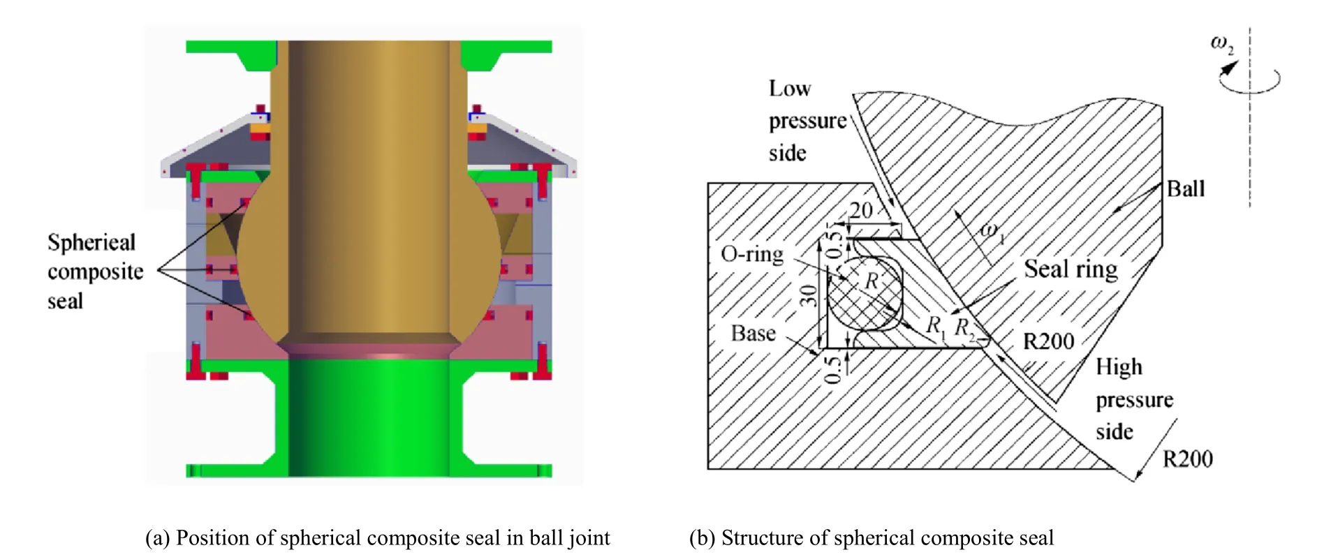
Fig.1 Geometric model of spherical composite seal
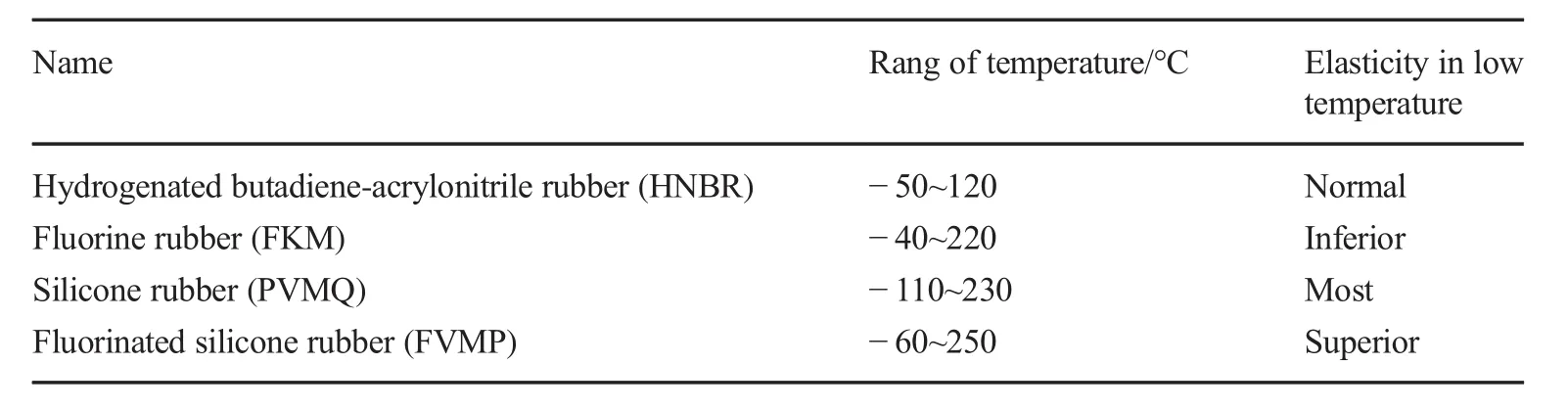
Table 1 Temperature properties and elasticity of common rubbers
3 Calculation of Contact Stress
According to Bernard et al.(2015),sealing performance is measured mainly by the following:(1)the maximum pressure difference the seal can endure and(2)the maximum contact stress of the sealing surfaces.The seal works normally only if the maximum contact stress is larger than the pressure difference,and the greater the contact stress,the better the sealing performance.Otherwise,the seal should be redesigned.The O-ring shows typical material,geometric,and contact nonlinearity.To work out the contact stress and determine the measurement of sealing performance,nonlinear theory must be introduced as follows:
3.1 Material Nonlinearity
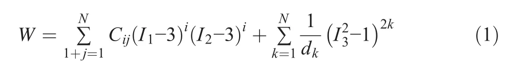
Generally,the material nonlinearity of rubber is described by the Mooney-Rivlin model(Mooney 1940;Batra and Ching 2002;Jahani and Mahmoodzade 2014;Karimi and Navidbakhsh 2015).The strain energy density function expression can be expressed as follows:
The second-order trinomial can be determined by:
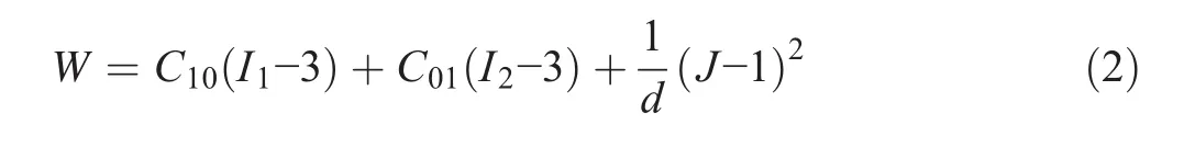
where W is strain energy density and I1,I2,and I3are the first,second,and third strain tensor invariants for an incompressible material,I3≡ 1.C10,C01,and d are the material’s Mooney-Rivlin coefficients.These are usually measured with experimental data but are difficult to measure in engineering;however,they can be selected using the method of Wang et al.2004,assuming C01=0.35C10:

where H is Shore hardness, μ is Poisson’s ratio, μ = 0.4995, and E is the elastic modulus (MPa). According to Eq. (2), the differences in Shore hardness and the values of E,C01,C10,and d01are shown in Table 2.
The O-ring’s stress-strain relationship was studied using Kirchhoff’s and Green’s strain tensors,that is:

The relationship between the principal stress tiand principal elongation ratio λiof the rubber is:
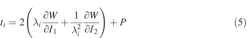
where P is the static pressure of an arbitrary fluid.
3.2 Geometry Nonlinearity
Geometry nonlinearity means that the relationship between a material’s stress and displacement under large deformation is nonlinear.An augmented Lagrange equilibrium equation was used to solve the rubber’s geometry nonlinearity. According to Borst et al.(1993),an equation that employs the principle of virtual work can be used to work out the dynamic variables at t+ Δt.The virtual work equation indicates an object’s balance situation at t+Δt and its expression is:

wheret+Δtδijis the Cauchy stress tensor at a Cartesian coordinate;
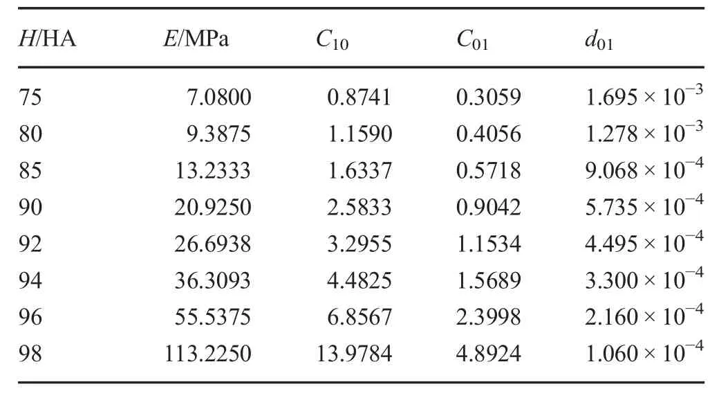
Table 2 O-ring Shore hardness H and the relationships of E,C01,C10,and d01
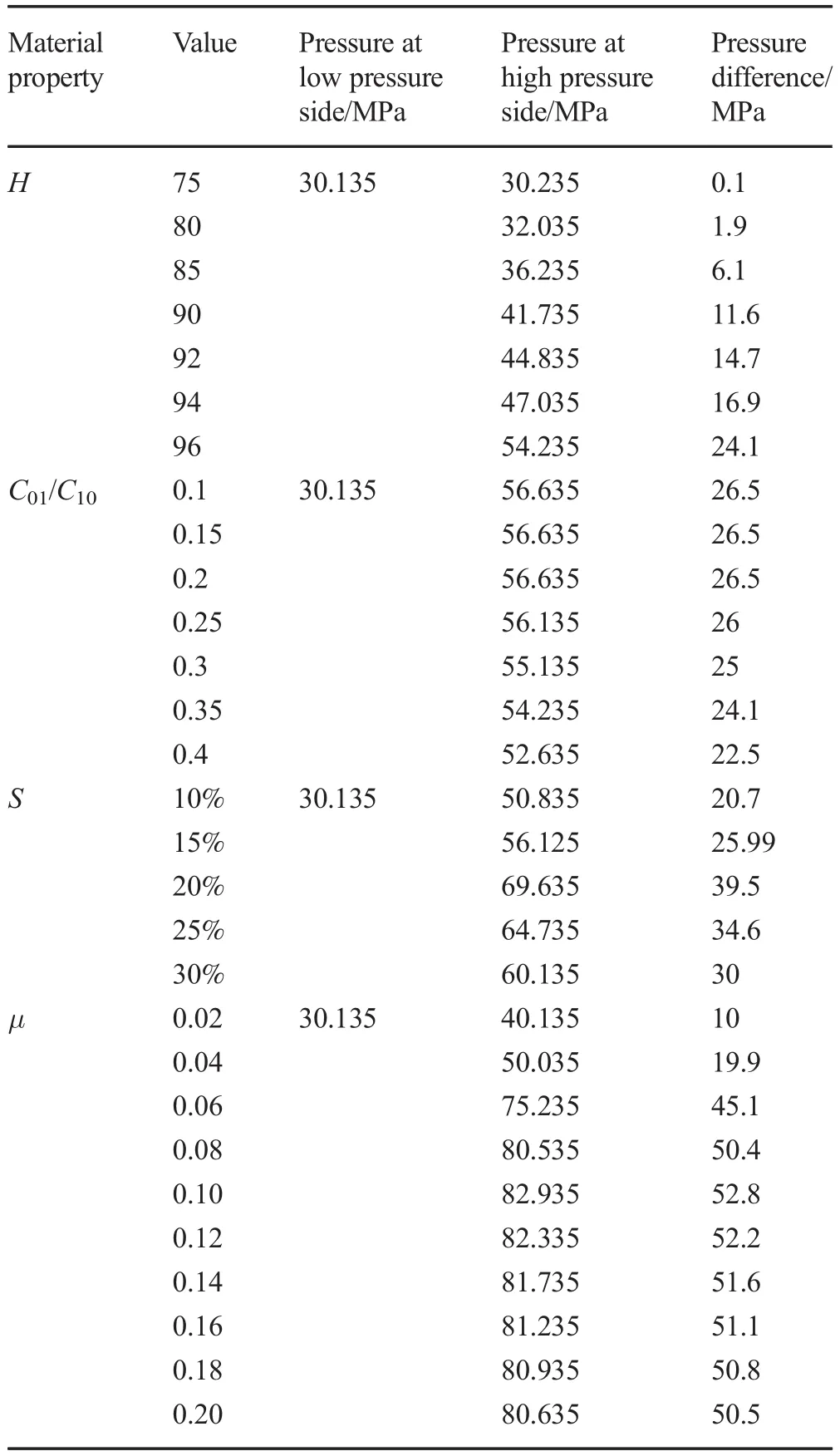
Table 3 Pressure difference dependence on O-ring material properties
t+ΔtR is the infinitesimal strain tensor at a Cartesian coordinate.
The Eq.(6)solved by the Total Lagrangian method is:
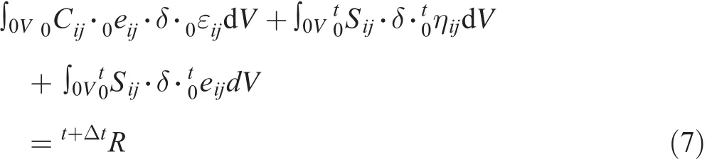
where0Cijis the constitutive tensor,0eijis the linear part of strain increment,0εijis the strain increment,t0Sijis the Kirchhoff stress increment,andt0ηijis the nonlinear part of the strain increment.
The relationship between stress and displacement can be calculated out by repeated iteration of Eq.(7)until the result is small enough.
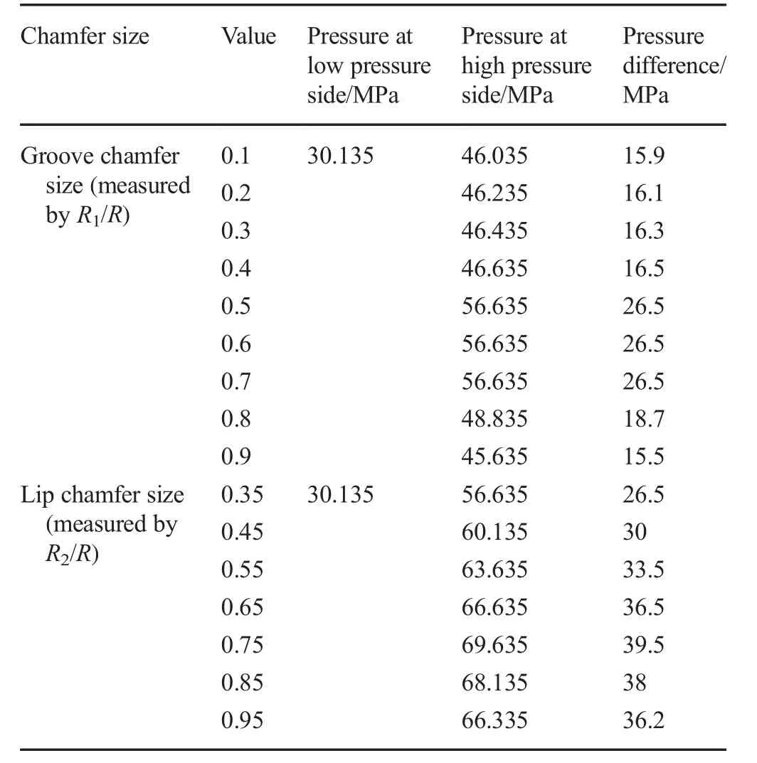
Table 4 Pressure difference with different seal ring chamfer sizes
3.3 Contact Nonlinearity
For rubber materials,the contact boundary usually belongs to a sliding boundary and the incremental consistent equation(Zhang and Zhan 1990)at the contact point is:
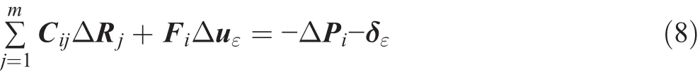
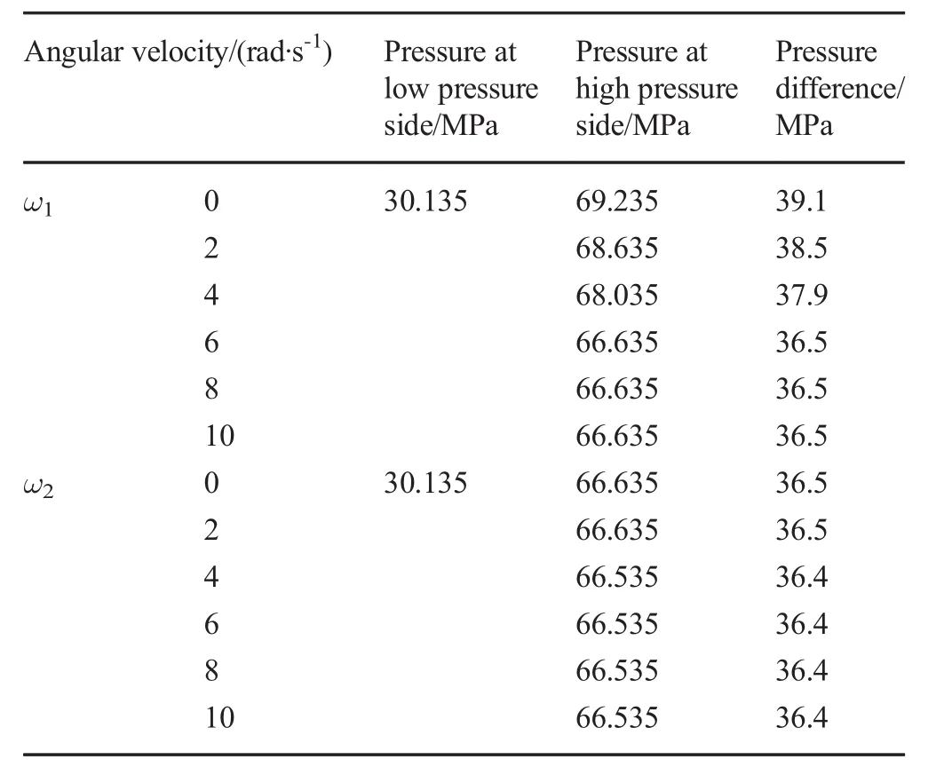
Table 5 Pressure difference with angular ball velocity

Fig.2 Deformation and contact stress under ΔP=0 MPa and ΔP=39.5 MPa
On the sliding boundary,the equations at the x component and y component are:
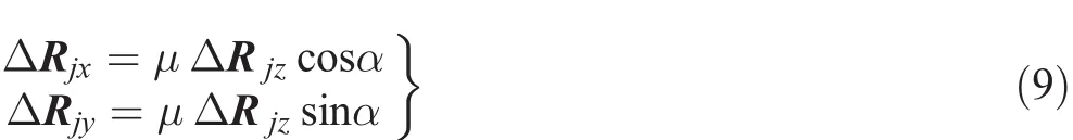
ΔRjthe incremental displacement vector at point j of the l load part
Fithe displacement matrix vector of rigid body
Δuεthe incremental contact force at the l load part
ΔPithe incremental load at point i of l load part
δεthe gap vector at i point of l-1 load part
The stress-strain relationship of the O-ring can be calculated using Eqs.(1)to(5).Equations(6)and(7)can be used to deduce the stress-displacement relationship.If the boundary conditions of load and displacement are determined,the contact stress at any point can be calculated based on Eqs.(8)and(9)by repeated iteration.
4 Simulation
Nonlinear contact stress at any point on the contact surface under a fixed state can be derived by theoretical calculation;however,contact stress at all points on the contact surface under complex factors needs to rely on the powerful simulation ability of a workbench.In addition,pressure differences and contact stress reflect the sealing performance.Therefore,the maximum pressure difference on the spherical seal,the maximum contact stress of all points on the contact surface,and several other main factors influencing sealing performance are simulated using a workbench.The results follow.
Fig.3 Influence of O-ring material properties
4.1 Maximum Pressure Difference
In deep-water drilling,the lower ball joint needs to withstand high pressures. Therefore, in this paper, to simulate the changes in maximum internal hydraulic pressure of a ball joint under various conditions,we assume a water depth of 3 000 m and an external hydraulic pressure of 30.135 MPa.The results are shown in Tables 3,4,and 5.
The O-ring is made of nonlinear silicone rubber and a slight change in material properties can greatly affect the pressure difference.Therefore,the properties of the O-ring become the primary factors for sealing performance.These include as follows:Shores hardness H,fraction factor μ,compression ratio S,and the ratio of C01/C10;their influence on the maximum pressure difference is shown in Table 3.It can be seen that Shore hardness H is the most important influencing factor,second is the fraction factor μ of the O-ring,third is the compression ratio S,and last is C01/C10.By selecting O-rings with reasonable properties,the pressure difference in the spherical seal ranges from 0.1 to 52.8 MPa,which beats that of traditional seals.In addition,the results verify that the spherical seal designed in this paper can work effectively under high-pressure conditions.
Table 4 shows how the geometry size of the seal ring influences the maximum pressure difference.The pressure differences range from 15.5 to 39.5 MPa while groove chamfer sizes are R1/R=0.1~0.9 and lip chamfer sizes are R2/R=0.35~0.95.The optimum occurs at R1=0.4~0.6R and R2=0.75R with the pressure on the high-pressure side,and the pressure differences in the seal reach a maximum under the optimum groove size.The values in this chart demonstrate that the geometry structure of the seal ring largely affects the sealing performance.Appropriate choice of chamfer sizes for seal rings is necessary in engineering.Compared with the other factors,the chamfer size of the seal ring is one of the primary influences.
Fig.4 Influence of seal ring chamfer size on maximum contact stress
In practical applications,the ball joint experiences certain angular rotation,which influences the sealing performance.Table 5 shows the results of the pressure difference when the ball joint experienced rotation.At first,the pressure difference slightly reduces from the maximum(at ω1,ω2=0),and then,the values remain stable no matter how the angular velocity ω1and ω2increases.This indicates that rotation of the ball barely influences the pressure difference.
4.2 Maximum Contact Stress
Figure 2 shows the total deformation and contact stress at the contact surfaces.Compared with Figs.2a,b,the spherical seal distorts highly under a high-pressure difference,but the contact of the sealing surfaces is still favorable.In Fig.2c,σ1is the maximum contact stress between the ball and the seal ring;σ2is the maximum contact stress between the O-ring and the base;and σ3is the maximum contact stress between the Oring and the seal ring. By combining with panels c and d, it can be seen that the maximal contact stress lies in the spherical surface of the seal ring and that the contact stresses at the O-ring and base,O-ring and seal ring,and seal ring and base are relatively large.By comparing Figs.2c,d,it can be seen that the contact stress values are larger than the pressure difference,which means the spherical seal works effectively under 39.5 MPa.This demonstrates that the structural design is reasonable.
5 Influence Factors of Contact Stress
5.1 Material Property of the O-Ring
Figure 3 shows the contact stress under various material properties of the O-ring.In Figs.3a,b,σ1,σ2,and σ3increase with Shores hardness and decrease with the ratio C01/C10.A greater Shores hardness makes it more difficult to compress the O-ring;thus,the contact stress is larger;C01/C10affects thestress-strain relationship of the O-ring and finally affects the contact stress. In Fig. 3c, with an increase in compression ratio S,the contact stresses,σ1,σ2,and σ3,increase to maximum at first then finally decrease to the origin.This is mainly because the O-ring breaks if S is too small and the seal surfaces are easily separated from contact surfaces if S is too large.Figure 3d shows the contact stress under various fraction factors μ,where σ1,σ2,and σ3drastically increase when fraction factor μ =0.02~0.08 and then remain no matter how μ increases.
Fig.5 Maximum contact stress under various angular velocities
From these figures,we can conclude that Shores hardness is the principal influencing factor for contact stress,the fraction factor μ is the next,and C01/C10the least.
5.2 Geometry Size of the Sealing Ring
Figure 4a,b shows the maximum contact stress of the geometry size(chamfer R1,R2).At first,the values increase gradually to an optimum,then decrease gradually to a common value.This is mainly because if the chamfer of groove R1is too small,this leads to stress concentration at the seal ring and if it is too large,this leads to the O-ring being crushed.The lip chamfer R2if too small leads to stress concentration at the lip chamfer and if too large reduces the effectively contact area of the sealing surface.Figure 4c,d show the contact stress contours under different chamfers.
5.3 Angular Velocity
In Fig.5a,b,the maximum contact stress merely changes with an increase in the angular velocity of the ball.This indicates that the angular velocities(ω1and ω2shown in Fig.1b)barely influence the sealing performance.
From all the charts above,we deduce that the maximum contact stress is always larger than the pressure difference ΔP,which means that the spherical seal can normally work under an arbitrary pressure difference bellow ΔP(Fig.5 red dotted line).The O-ring material was found to be the most significant influencing factor on sealing performance and ball rotation barely influenced it at all.
6 Conclusion
The proposed spherical seal,for use in a deep-water drilling ball joint,is shown to be of rational structural design and,compared with traditional techniques,requires lower sphere machining precision,is convenient to replace,and exhibits a high pressure difference and outstanding sealing performance.This significantly reduces the machining and maintenance costs of spherical seals.Using nonlinear theories and a finite element technique,this paper presents the sealing performance of a spherical seal under various factors.The results demonstrate the practicality of the spherical seal for use in a deep-water drilling ball joint and provide theoretical evidence for practical applications.
 Journal of Marine Science and Application2018年2期
- Journal of Marine Science and Application的其它文章
- Fast Ferry Smoothing Motion via Intelligent PD Controller
- Internal Resonances for the Heave Roll and Pitch Modes of a Spar Platform Considering Wave and Vortex Exciting Loads in Heave Main Resonance
- Comparison of Scour and Flow Characteristics Around Circular and Oblong Bridge Piers in Seepage Affected Alluvial Channels
- Empirical Equilibrium Beach Profiles Along the Eastern Tombolo of Giens
- Determining the Scour Dimensions Around Submerged Vanes in a 180°Bend with the Gene Expression Programming Technique
- Influence of Short Time-Scale Water-Column Temperature Fluctuations on Broadband Signal Angular Beam Spreading