永磁同步电机电流环频率响应改进策略研究
肖海峰 贺昱耀 乔社娟


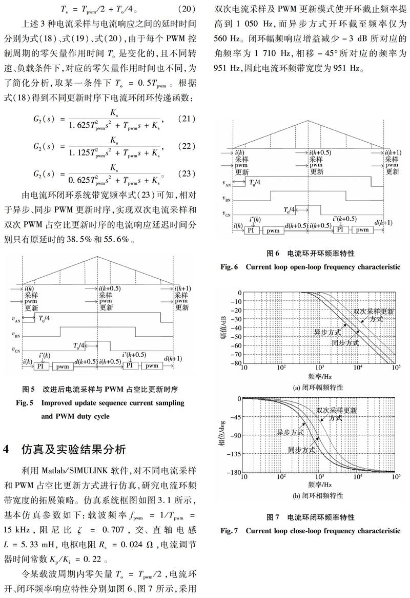
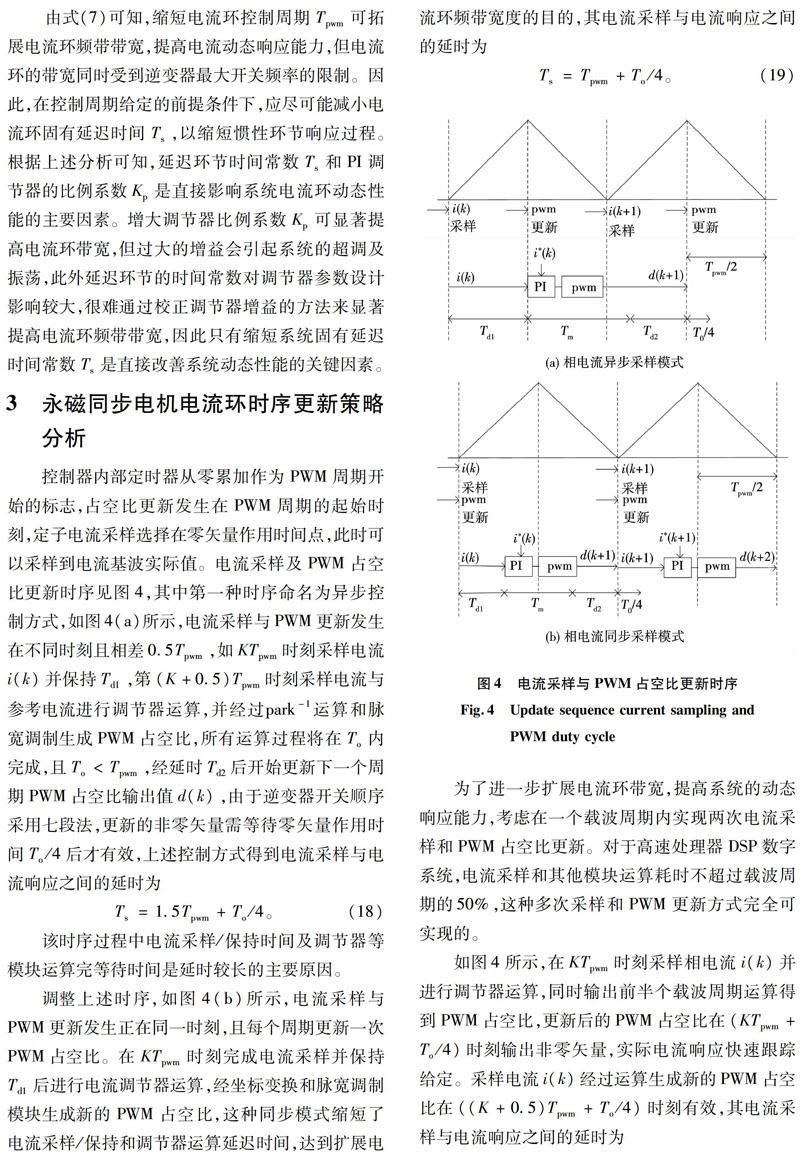
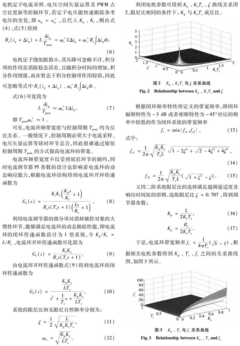
摘 要:针对永磁同步电机矢量控制电流环内存在的固有延迟环节,如电流采样、占空比计算、逆变器死区效应及数字控制延时等。在同步旋转坐标系下引入电流解耦项jωrL,分析制约电流环频率响应能力的主要迟滞因素,并对比不同电流采样时刻与脉宽调制(pulse width modulation,PWM)占空比更新时序对电流环频率响应的影响。提出了一种新的电流采样时机和更新输出PWM信号模式,在半个载波周期内优化采样、计算和输出时序,减小了电流环固有延时等待时间。在载波频率不变的前提下,提高电流环动态加速过程中电流的跟踪性能。仿真和实验结果与理论分析基本吻合,电流环的频率频带带宽提高了近一倍,表明该策略的有效性和正确性。
关键词:永磁同步电机;频率响应;占空比更新;脉宽调制;电流环
中图分类号:TP 273
文献标志码:A
文章编号:1007-449X(2018)06-0107-07
Abstract:Considering the inherent delay existing in the current loop of permanent magnet synchronous motor, such as the current sampling, duty ratio calculation, inverter deadtime effect and digital control delay, etc, it introduces the current decoupling jωrL in the synchronous rotating reference frame, conducts the analysis of main hysteresis factor restricting current loop frequency response ability, and comparison of impact of different current sampling time and renewal of the PWM duty cycle on current loop frequency response. This paper proposed a new current sampling time and updated the output PWM signal model. The optimization calculation and output sequence in half a carrier cycle sampling were achieved to reduce the current loop inherent delay. The current loop current in the process of dynamic tracking performance was improved under the premise of the invariable carrier frequency. The simulation and experimental results are in accordance with the basic theoretical analysis, and the current loop bandwidth of frequency band can be nearly increased by double.
Keywords:permanent magnet synchronous motor; frequency response; duty ratio updates; pulse width modulation;current loop
0 引 言
交流永磁同步電机调速系统的动、静态特性主要由两个嵌套的控制环性能决定,即电流环、速度环,而内环电流环的动态响应能力是制约整个系统性能的关键,其主要采用的控制策略为滞环控制、比例积分(proportional integral, PI)控制以及智能控制等。
在中、小功率调速系统中仅仅依靠改变电流控制策略很难满足调速系统的动态要求[1-4]。文献[5]分析了滞环电流控制动态响应快的特点,但该策略开关引起的谐波频带分布较宽,而过多的滤波环节会降低系统电流响应;基于PI调节器的电流控制以固定的开关频率和较好的稳态、动态性能等优点,但PI调节器的自身滤波特性也将影响系统的频率响应[6-8];采用了滑模变结构等智能控制方案可以有效改进电流环动态性能,但对于电机控制系统内固有的迟滞无法消除[9-10]。
在电流环中还存在着诸多其他主要迟滞因素,如相电流滤波、电流采样/保持、矢量控制算法及PWM输出更新延时[11-12]。本文通过永磁同步电机调速系统连续模型,仅对PI调节器滤波特性、PWM计算、更新及电流采样之间的时序关系进行详细分析,针对时序中存在的延时进行优化,提出新的电流采样时机与PWM占空比更新时序,在半个载波周期内完成电流采样、矢量计算和指令输出等环节,减小了电流环固有延时等待时间,提高系统动态响应时间。为了保持电流采样精确度,同时兼顾滤波效果和延时影响[13],选取低通滤波器的截止频率约为开关频率的两倍。通过采用Matlab/SIMULINK构建矢量控制系统模型,分别针对不同电流环工作时序模式进行仿真分析,并结合1.5 kW永磁同步电机开展了实验验证。
1 永磁同步电机数学模型
2 永磁同步电机电流环动态响应性能分析
在同步旋转坐标系dq下,建立永磁同步电机交流调速系统电流环连续控制模型,如图1所示。电流环的反馈滞后项和电流调节器位于同步坐标系,而触发信号的输出和被控对象位于静止坐标系,通过坐标变换构成完整的闭环系统。为了消除交、直轴之间存在电流交叉耦合,在同步旋转坐标系下引入电流解耦项jωrL以实现交、直轴电流独立控制[14]。
图8为不同参考电流给定信号的响应波形。在双次采样更新方式下,如图8(a)所示,q轴阶跃响应电流能更快的跟踪参考给定,且调整时间和最大波动值都小于异步采样更新方式。当参考给定为300 Hz正弦电流信号时,如图8(b)所示,双次采样更新方式电流响应与参考电流存在0.000 15 s的延时,即相角滞后16.2°,异步采样更新方式电流响应延时达0.000 35 s,即相角滞后37.8°。由仿真结果可知在一个载波周期内提高电流采样频率和PWM更新频率能够有效拓展电流环带宽,改善实际转矩的快速性。
在永磁同步电机调速系统实验平台上,验证不同电流采样和PWM更新模式电流响应速度,实验所用电机额定功率为1.5 kW,极对数为4,相关实验参数如下:电流采样周期为2 us;PWM开关频率为15 kHz。电机正弦给定信号频率为166.6 Hz,如图9(a)所示为异步模式下电机相电流响应波形,电流采样与电流响应之间的理论延时只有1.625Tpwm,但考虑到滤波器和电机时间常数等因素,实际电流相位滞后达2 ms,且存在约为0.1 A的幅度衰减。在电流同步采样时序下,电机相电流相位滞后减小,滞后时间约为1.5 ms,幅度衰减减小到为0.07 A,如图9(b)。改进后的电流采样与PWM占空比更新时序,如图9(c),实际电流相位滞后小于1 ms,同时电流具有较小的衰减幅度,对比不同的电流采样和PWM更新时序模式,相电流响应得到明显的提高,拓展了调速系统电流环的带宽。
5 结 论
本文改进电流采样与PWM更新时序,即在一个载波周期内实现增加电流采样和PWM更新次数,缩短了电流环控制周期,提高电流环动态响应能力。采用1.5 kW永磁同步电机构建矢量控制系统,进行了所提出控制策略有效性的验证。仿真和实验结果表明该方法可有效提高电流环动态响应能力,有着较大的工程价值和实际意义。
参 考 文 献:
[1] CHOI J, KIM H, SUL S K.Design of fast response current controller using dq axis crosscoupling application to permanent magnet synchronous motor drive[C]//International Conference on Industrial Electronics, Control, and Instrumentation. Melbourne: IEEE,1996:1187.
[2] LI S H, ZONG K, LIU H X.A composite speed controller based on a secondorder model of PMSMsystem[J].Transactions of the Institute of Measurement and Control, 2011, 33(5):522.
[3] BLANCO F B, DEGNER M W, LORENZ R D. Analysis and design of current regulators using complex vectors[J].IEEE Transactions on Industry Applications, 2000, 36(3):817.
[4] TARCZYNSKI W,HEJMAN T,SMUGALA D.Computer controlled testing system for investigating the dynamic characteristics of contactors with AC electromagnet drives[J]. Measurement, 2003,(33):313.
[5] 张成, 孙驰, 艾胜, 等. 控制网络延时对SPWM逆变器输出电压的影响[J]. 电工技术学报, 2013,28(8):194.
ZHANG Cheng, SUN Chi, AI Sheng, et al.Influence of control network delay on output voltage of SPWM inverter[J].Electric Machines and Control,2013,28(8):194.
[6] JUNG J, NAM K. A dynamic decoupling control scheme for highspeed operation of induction motors[J]. IEEE Transactions on Industrial Electronics,1999, 46(1):100.
[7] 李春龙,沈颂华,卢家林,等. 具有延时补偿的数字控制在PWM整流器中的应用[J]. 中国电机工程学报,2007, 27(7): 94.
LI Chunlong,SHEN Songhua,LU Jialin,et al. Digital control with compensation of delay for PWM rectifier[J].Proceedings of the CSEE, 2007, 27(7): 94.
[8] 贺明智,许建平, 游小杰, 等.环路延时对数字峰值电压控制开关变换器瞬态性能的影響[J].中国电机工程学报, 2009, 29(6):1.
HE Mingzhi, XU Jianping, YOU Xiaojie, et al. Time delay effect ontransient performance of digital peak voltage controlled switching converter[J]. Proceedings of the CSEE, 2009, 29(6):1.
[9] KAKU B, MIYASHITA I,SONE S.Switching loss minimised space vector PWM method for IGBT threelevel inverter[J]. IEEE Proceedings Electric Power Applications, 1997, 144(3):182.
[10] JEONG S J, SONG S H. Improvement of predictive current control performance using online parameter estimation in phase controlled rectifier[J]. IEEE Transactions on Power Electronics, 2007, 22(5):1820.
[11] MOREL F,LINSHI X, RTIF J M,et al.A comparative study of predictive current control schemes for apermanentmagnet synchronous machine drive[J]. IEEE Trans on Industrial Electronics, 2009, 56(7):2715.
[12] BLAABJERG F, KJAER P C, RASMUSSEN P O, et al. Improved digital current control methods in switched reluctance motor drives[J]. IEEE Transactions on Power Electronics, 1999, 14(3):563.
[13] LAAKKONEN T. Distributed control architecture of power electronics buildingblockbased frequency converters[D]. Lappeenranta:Lappeenranta University of Technology, 2010.
(編辑:贾志超)

