The influence of surface roughness on cloud cavitation flow around hydrofoils
Jiafeng Hao·Mindi Zhang·Xu Huang
1 Introduction
It is well known that surface roughness is one of the important factors affecting cloud cavitation.Surface roughness influences the boundary layer and turbulent structure,both of which are important for the occurrence of cavitating flow[4–6].Rood[7]summarized that the surface roughness has an effect on the inception of cavitation by itself as a source of nuclei,as well as stimulating flow instabilities.Surface roughness can enhance flow instability through a variety of mechanisms depending on the size and spatial distribution of the roughness elements[8–10].Stutz and Reboud[11,12]studied the influence of roughness on the two-phase flow structure of sheet cavitation within a Venturi-type test section with the help of a double optical probe.The conclusions indicated that surface roughness may not significantly influence the shape and void fraction of cavitation.
However,the effect of surface roughness on cloud cavitating flow is still not well understood,hence additional study is still required.To further research the effect of the roughness distribution on the flow structure in cloud cavitation,in this present work,experiments were conducted to observe this structure and the development of cavitating flow around Clark-Y hydrofoils.
2 Experimental setup
Experiments studies were carried out in a closed-loop cavitation tunnel located at Beijing Institute of Technology.The primary characteristics of the experimental setup are summarized here;more information about the instrumentation with experimental uncertainties and the test section was presented by Biao Huang et al.[13].Ahigh-speed particle image velocimetry(PIV)system provided by Dantec was used;see Ref.[13]for additional information.In the experiments,the development of the cavitating flow around the hydrofoil was observed for various cavitation numbers at velocity ofV∞=8 ms−1.The chord length of the hydrofoils was 70 mm,and the angle of attack was set as 8◦.The Reynolds number and cavitation number were defined as in Ref.[1].As cavitating flow can be influenced by surface characteristics[14],two hydrofoils were machined from the same material and subjected to grit blasting to obtain different surface roughnesses.As shown in Fig.1,the surface of hydrofoil A was relatively smooth withRa=0.48µm,while the surface of hydrofoil B was rough withRa=6.9µm.
During the experiment,we adjusted the speed of the axial flow pump to control the inlet velocity or controlled the ambient pressure to adjust the cavitation number.Furthermore,a series of pictures were obtained during the experiment using high-speed cameras to analyze the structure of cavitation and its development,and for detailed flow visualization.
The cavitation number is denoted byσ,defined asfollows

The Reynolds number is defined as follows
对村庄空间的整治规划应分为2个方面进行规划:首先是村庄布点规划,应从宏观角度出发对乡村发展中存在的问题进行有效地解决,提高当地居民的生产和生活条件。其次是村庄建设规划,主要是从微观角度上对村庄之间的问题进行解决[2]。

The location coefficientsx′andy′were defined as follows

The time coefficientt′was defined as follows

wherep∞,p v,andV∞are the reference static pressure,saturated vapor pressure of water,and free stream velocity,respectively.ρis the water density.υ,l,andαare the kinetic viscosity,hydrofoilchord length,and angle of attack,respectively.Tis the period of the cavitation flow.
3 Results and discussion
3.1 Flow structure of cloud cavitation

Fig.1 Surface pattern of Clark-Y hydrofoil

Fig.2 continued
To investigate the effect of roughness on the cloud cavitating flow,Fig.shows the time evolution of the cloud cavitating flow around hydrofoil A and hydrofoil B withσ=1.02 in upward and side views.As seen in Fig.2a,the period of the cloud cavitation was 52 ms.The development of cloud cavitation consisted of two stages:(1)Fort=t0+0 ms−t0+40 ms,an attached cavity developed along the surface of hydrofoil A fromx′=0.3 to the trailing edge.Some ambient bubbles shed when it reached the trailing edge att=t0+40 ms.This means that the length of the cavity increased by aboutΔx′=0.7 during 40 ms,yielding an average cavity growth rate of 1.2 ms−1;(2)Whent=t0+40 ms−t0+52 ms,the adverse pressure gradient was strong enough to overcome the weaker momentum of the flow in the near-wall region.A reentrant jet formed and pushed the flow along the suction side toward the leading edge of the foil.Based on the development of the front part of the reentrant jetfromx′=0.53 tox′=0.27 att=t0+40 ms−t0+52 ms,the velocity of the reentrant jet was estimated to be 1.5 ms−1.When the reentrant flow reached the vicinity of the cavity leading edge,the cavity fluctuated and shed toward the front,then bubble clusters were shed and collapsed at the end of the period.Whent=t0+50 ms,shedding of bubble clusters resulted in an obvious vortex pair structure,linked with a vortex braid.Lines fromatocindicate the movement of the reentrant jet.

Fig.2 continued

Fig.3 a Comparisons of time evolution of cavity area around different hydrofoils obtained by experiment.b Comparisons of cavity area spectrum around different hydrofoils(σ =1.02,R e=5.6×10⁵)
As shown in Fig.2b,the process of cloud cavitation around hydrofoil B consisted of three stages:(1)Whent=t0+0 ms−t0+28 ms,attached cavities developed along the surface of hydrofoil B fromx′=0.3 to the trail-ing edge,with growth rate of about 1.7 ms−1.(2)Whent=t0+28 ms−t0+50 ms,attached cavities at the leading edge fluctuated violently,then collapsed into bubbles.However,the length of the cavities remained at aboutx′=0.3 untilt= 40 ms,then the attached cavities grew again.The rear part of the cavities developed fromx′=0.25 tox′=0.6,with growth rate of about 2.4 ms−1.(3)Whent=t0+50 ms−t0+57 ms,cavities broke off and shed again.The rear part of the cavities shrank fromx′=0.6 tox′=0.22.
Comparison of Fig.2a and 2b reveals some differences in the cloud cavitating flow around hydrofoil A and hydrofoil B.Firstly,the flow structure of the cloud cavitation flow was different.The intensive roughness distributed on the surface of hydrofoil B resulted in attached subulate cavities,while the finger-like cavities on the surface of hydrofoil A were caused by flow separation.The period of the cloud cavity around hydrofoil A and hydrofoil B was also different at 52 and 57 ms,respectively.Besides,we observed development of a reentrant jet and cavity collapse on the surface of hydrofoil A,but in the second stage of cavitating flow around hydrofoil B,cavities broke off quickly without an obvious reentrant jet.Secondly,the growth rate of the cloud cavity along the surface of hydrofoil A was about 1.2 ms−1,compared with about 1.7 ms−1for hydrofoil B,illustrating that cavitation due to roughness showed higher evaporation rate,and cavities developed more quickly.The larger-scale flow separation caused by the rougher surface provided an evaporation rate sufficient for formation of subulate cavities.
To further investigate the cloud cavitating flow around hydrofoil A and hydrofoil B,we applied the method of Zhang et al.[15]to determine the cavity area for each cloud cavitating flow.We applied many image processing functions that differ from those traditionally used as well as an in-house feature-recognition software package to overcome restrictions in commercial software.This enabled successful extraction of the outline,boundary,gray level,and area from images of the flow around the hydrofoilin the cavitation zone.Moreover,the evolution period of cavitation could be estimated based on gray levelimages.Figure 3 a presents the time evolution of the nondimensional cavity area,which changes periodically.As shown in Fig.3a,the curves for the cavity area of the cloud cavitating flow around both hydrofoil A and hydrofoil B present the same fluctuation rule.Increasing cavity area represents the process of cavity growth and accumulation near the trailing region of the hydrofoil,while decreasing cavity area represents the process of shedding and collapse of bubble clusters near the trailing region of the hydrofoil.These curves conform well to the observed development of cloud cavitating flow around the hydrofoils.The curve in Fig.3a shows that the maximum nondimensional cavity area around hydrofoil B was larger than that for hydrofoil A,indicating that the cavitating flow around hydrofoil B was more intense and its evaporation rate was higher.Figure 3b presents comparisons of the cavity area spectrum around the different hydrofoils after fast Fourier transform(FFT)analysis of the cavity area evolution.It is observed that the main frequency of evolution of the cavity area around hydrofoil B was higher than that for hydrofoil A atf=20 Hz andf=17 Hz,respectively.Thus,the main frequency of evolution of cloud cavitation around the different hydrofoils was different.
3.2 Velocity and vorticity distribution of cloud cavitation
Cavities broke off quickly without an obvious reentrant jet in the second stage of the cavitating flow around hydrofoil B whenσwas 1.02.As is well known,initiation of typical cloud cavitation begins with the formation of a reentrant jet at the trailing edge of a sheet cavity[10].To further show that the surface roughness had a great influence on the typical cloud cavitation,we compared typical cloud cavitation around hydrofoil B with hydrofoil A(σ=1.02).Forσof 0.87,the velocity and vorticity distribution of typical cloud cavitation around hydrofoil B are discussed based on PIV results.
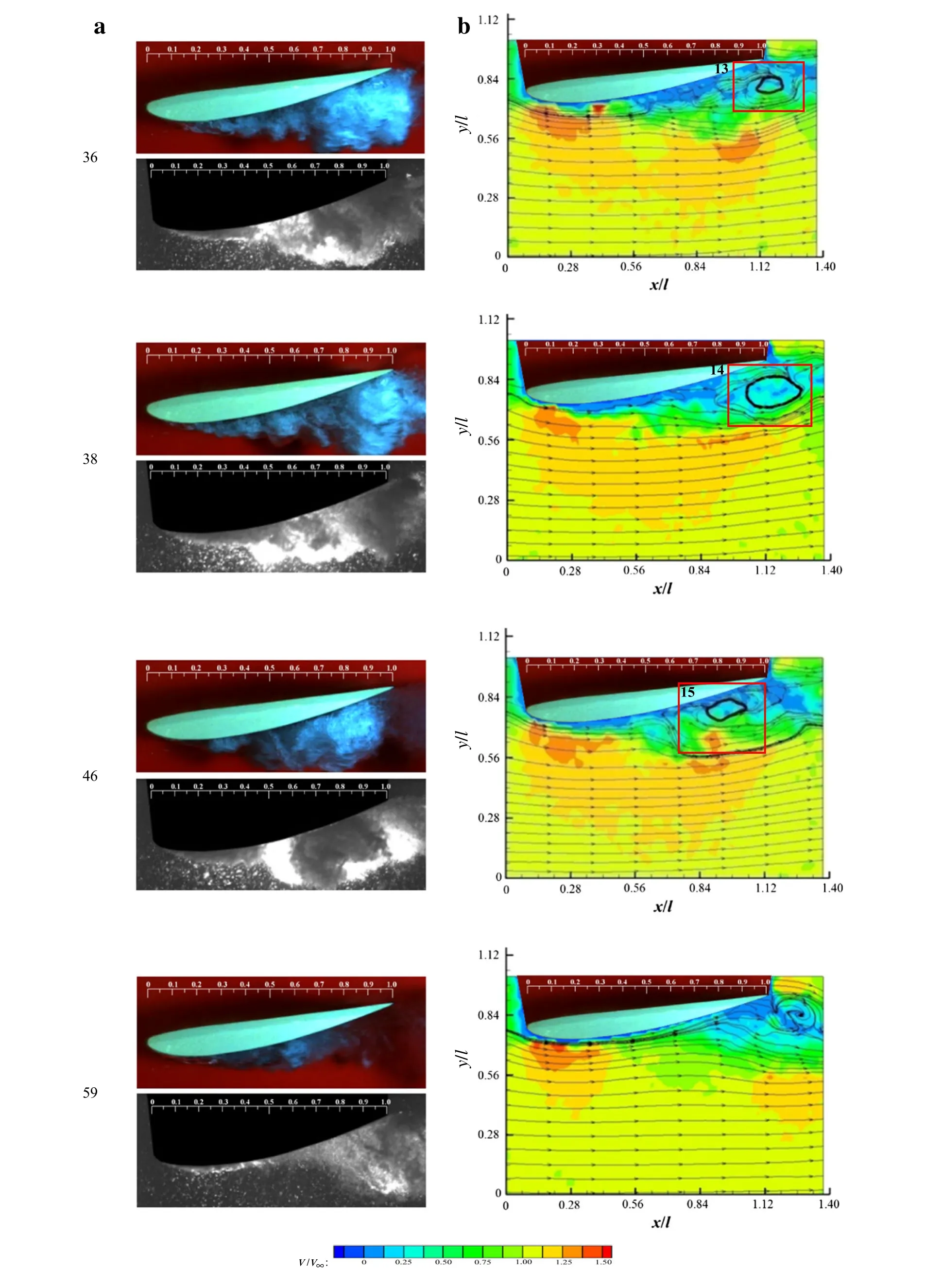
In the experiments,the flow field was measured using PIV images acquired at 2000 Hz.Figure 4 presents the time evolution of the profile of the flow field and velocity field.The velocity field diagram is overlaid with a streamline chart.
As shown in Fig.4,apparently,the whole flow field could be divided into three areas:the near-wall region,the wake region on the suction side,and the free stream area.(1)The near-wall region except at the front of the suction side was an obvious low-velocity area.The velocity in the near-wall region decreased fromx′=0 tox′=0.5,then remained at about 2 ms−1at aboutx′=0.5 with little velocity fluctuation.(2)The velocity in the wake region of the suction side was about 3–5 ms−1.(3)The velocity in the free stream area was about 8–10 ms−1,and at the front part,the velocity reached a maximum of 12 ms−1atx′=0.03–0.05.The velocity distributions of the flow field formed large-scale shearflow regionsamong these three areas,providing energy for development of cavitation and movement of vorticity.
Whent=0 ms,cavities attached to the front region of hydrofoil B,and the velocity in the near-wall region was low.The few bubbles atx′=0–0.45 had no obvious effect on the velocity distributions,and the streamlines were continuous.As shown in Box 1,a large-scale vortex formed from the bubble cluster in the previous period in the wake region,since the shear flow had a great influence on the process of shedding.Meanwhile,a smaller-scale vortex formed in the downstream area of the large-scale vortex owing to the flow interaction with the pressure side.

Fig.4 Time evolution of a flow field profile and b velocity field diagram and streamline chart.(Red rectangle is named as Box and the vortexes were enclosed by Boxes)

Fig.4 continued

Fig.4 continued
Whent=t0+22 ms−1,the cavity length increased to 0.8land bubbles in the cavitating wake region shed gradually,decreasing the length of the attached cavity.Box 2 shows the vortex caused by shedding of some bubbles.
Whent=t0+28 ms,the cavity developed tox′=1.0.During the cavity shedding process,the cavity sheared off from the pressure side and shear flow formed along the suction side in the cavitating wake region.Whent=t0+29 ms,as shown in Box 4,some cavitiesin the cavitating wake region entered the closed region in the form of vortex motion,moved forward at speed of−3 ms−1,then formed a large-scale vortex due to shear flow from the free stream area,as shown in Box 5 att=t0+30 ms.
Whent=t0+31 ms,the flow velocities of the suction side and pressure side were about 8.7 and 7.2 ms−1,respectively,while the flow velocity in the wake region was only 1.2 − 2.5 ms−1.When the vortex in Box 5 traveled downstream,two shear flows with opposite direction from the suction and pressure side formed a pair of vortices along the trailing edge,as shown in Box 6.When the vortex pair moved downstream att=t0+32 ms,as shown in Box 7,the anticlockwise vortex on the left developed into a single vortex near the suction surface continuously,while the clockwise vortex on the right disappeared.The bubble cluster at the trailing edge,as shown in Box 8,formed another anticlockwise vortex owing to the shear flows from the suction side.Therefore,a pair of anticlockwise vortices is observed in Boxes 7 and 8.
Whent=t0+33 ms,fluctuation of the flow from the suction side in Box 9 was caused by cavity shedding in the wake region,and the flow interacted with the anticlockwise vortex at the trailing edge and then moved toward the front att=t0+33.6 ms in Box 10.
Whent=t0+34 ms,the vortex at the front part of the suction side continued to rotate anticlockwise,but the scale of the vortex in the rear part increased obviously.The flow velocity was−4.3 ms−1atx′=0.95,but reduced to−2.4 ms−1atx′=0.85.Comparing the streamline chart and flow field pro file reveals that bright-white liquid–vapor mixture in the wall region,namely a reentrant jet,was induced toward upstream,as shown in Box 11,which is related to the two-phase flow att=t0+30 ms.
Whent=t0+35 ms,the reentrant jet developed tox′=0.65,resulting in cavity fracture and shedding,as shown in Box 12.Bubble cluster shedding resulted in formation of some vortices.When t=t0+36 ms,the large-scale bubble cluster at the rear part started to move downstream,forming a vortex due to its rotational motion,as shown in Box 13.The motion of the vortex was affected by two aspects:(1)more bubbles from the upstream moved with the continuous rotation of the vortex,increasing its scale,and(2)flow from the pressure side caused shedding and collapse of bubble clusters continuously.This resulted in formation of a large-scale vortex,as shown in Boxes 14 and 15.Whent=t0+38 ms,the vorticity of the large-scale vortex was 2070 s−1,and its diameter was about 0.4l.Whent=t0+46 ms,the vorticity of the large-scale vortex was 1750 s−1,and its diameter was about 0.6lwith center atx/l=0.98,y/l=0.77.
Whent=t0+59 ms,large-scale bubble clusters in the wake region shed and collapsed;the streamline chart indicated that the large-scale vortex nearly dissipated.The period of cloud cavitation was over whenσwas 0.87.
Figure 5 shows the velocity distribution in four red lines whent=t0+33.6 ms in Fig.4.The local thickness of the cavity was about 5 mm atx/l=0.98 andx/l=1.03,but the minimum velocity increased from−4 ms−1atx/l=0.98 to−2 ms−1atx/l=1.03.This means that the reverse velocity ranges significantly over the near-wall region of the rear part of the hydrofoil,resulting in the formation of a reentrant jet.The velocity field diagram indicates that the velocity atx′=0.9−1.0 was larger than−2 ms−1.The bubble density in the stream on the pressure surface and the air content of the liquid around the vortex were lower,leading to extremely low vapor content in the two-phase flows.
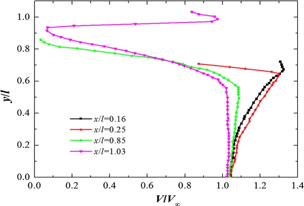
The velocity fields in the period of cloud cavitation were ensemble-averaged to obtain the velocity distributions of the flow field at various values ofx,as presented in Fig..The velocity atx/l=0.16 was nearly 8 − 10 ms−1,which is the velocity of the main stream(free stream)area.The velocity atx/l=0.25 reduced from 10 to 6.5 ms−1,showing an obvious velocity gradient in the near-wall region.The time-averaged velocity in the near-wall region at aboutx/l=0.85 was nearly 0 ms−1.The flows from the suction surface and pressure surface at the trailing edge were mixed atx/l>1.03,where isa velocity inflection point,indicating that the two shear flows affected the flow field in the wake region.

Fig.5 Velocity distributions of cloud cavitation flow fields around hydrofoil B when t=t0+33.6 ms

Fig.6 Time-averaged velocity distributions of cloud cavitation around hydrofoil B at various positions for σ of 0.87
4 Conclusions
The different effects of surface roughness on cloud cavitation were investigated experimentally using Clark-Y hydrofoils at fixed angle of attack ofα=8◦andR e=5.6×10⁵for two cavitation numbers ofσ=1.02 andσ=0.87,representing sheet and cloud cavitation conditions.High-speed videos of the evolution of the cloud cavitation and measurements of the velocity and vorticity fields by PIV were used to investigate the flow structure.The main results can be summarized as follows
(1)Surface roughness strongly influenced the development of cloud cavitation.For the smooth surface,it consisted of two stages:①An attached cavity developed along the surface to the trailing edge;②A reentrant jet developed,resulting in shedding and collapse of cluster bubbles or vortex structure.However,for hydro foil B with rougher surface,it comprised three stages:①An attached cavity developed along the surface to the trailing edge;② The development of a reentrant jet resulted in the first shedding of cavities.The interaction and movement of flows from the pressure side and suction side brought liquid water from the pressure side to the suction side of the hydrofoil, finally forming a reentrant jet.The jet kept moving along the surface to the leading edge of the hydrofoil,resulting in large-scale shedding of cloud bubbles.Several vortices appeared and dissipated during the process;③ The cavity grew and shed again.Besides,the period of cloud cavitation for hydrofoil A was shorter than that for hydrofoil B.
(2)The roughness significantly influenced the flow pattern and velocity and vorticity distributions of cloud cavitation.At the same cavitation number,for cavitating flow on the smooth surface of hydrofoil A,cloud cavitation occurred in the form of finger-like cavities,but for the rough hydrofoil B,it occurred in the form of attached subulate cavities.The nondimensional cavity area around hydrofoil B was larger than that around hydrofoil A,indicating that the cavitating flow around hydrofoil B was more intense.The growth rate of the cloud cavity along the surface of hydrofoil B was quickerthan that of hydrofoil A,indicating that its evaporation rate was higher.
(3)At the same cavitation number,the cavity on the rough surface could break off,shed,and collapse one more time in a period,which could lead to more severe cavitation erosion.
AcknowledgementsThe project was supported from the National Natural Science Foundation of China(Grant 51106009)and the China Scholarship Council(Grant 2011307311).
1.Wang,G.Y.,Senocak,I.,Shyy,W.,et al.:Dynamics of attached turbulent cavitating flows.Prog.Aerosp.Sci.37,551–581(2001)
2.Kawanami,Y.,Kato,H.,Yamaguchi,H.,et al.:Mechanism and control of cloud cavitation.J.Fluids Eng.119,788–794(1997)
3.Sato,K.,Shimojo,S.:Detailed observations on a starting mechanism for shedding of cavitation cloud.In:The 5th International Symposium on Cavitation,Japan,November(2015)
4.Wang,Z.Y.,Huang,B.,Wang,G.Y.,et al.:Experimental and numerical investigation of ventilated cavitating flow with special emphasis on gas leakage behavior and re-entrant jet dynamics.Ocean Eng.108,191–201(2015)
5.Huang,X.,Zhang,M.D.,Fu,X.N.:Experimental study of coatings’effect on cavitating flow.J.Ship Mech.19,35–42(2015)
6.Arndt,R.E.,Ippen,A.T.:Rough surface effects on cavitation inception.J.Fluids Eng.90,249–261(1968)
7.Rood,E.P.:Review–mechanisms of cavitation inception.J.Fluids Eng.113,85680U–85680U-7(1991)
8.Chang,J.C.,Huang,S.B.,Lin,C.B.:Effects of inlet surface roughness,texture,and nozzle material on cavitation.Atom.Sprays.16,299–318(2006)
9.Shimizu,S.,Ihara,A.,Okada,M.O.,et al.:Damage due to spot cavitation on hemispherical cylindrical body.Nippon KikaiGakkai Ronbunshu BHen/Transactions of the Japan Society of Mechanical Engineers Part B.68,1691–1696(2002)
10.Fathollah,V.,Dorothee,D.,Dierk,R.:Roughness-induced flow instability:a lattice Boltzmann study.J.Fluid Mech.573,191–209(2007)
11.Stutz,B.,Reboud,J.L.:Two-phase flow structure of sheet cavitation.Phys.Fluids.9,3678–3686(1997)
12.Stutz,B.:Influence of roughness on the two-phase flow structure of sheet cavitation.J.Fluids Eng.125,652–659(2003)
13.Huang,B.,Yin,L.Y.,Wang,G.,etal.:Combined experimental and computational investigation of unsteady structure of sheet/cloud cavitation.J.Fluids Eng.135,071301(2013)
14.Williams,M.,Kawakami,E.,Amromin,E.,etal.:Effects of surface characteristics on hydrofoil cavitation.In:Proceedings of the 7th International Symposium on Cavitation,Michigan,August(2009)
15.Zhang,M.,Song,X.,Wang,G.:Design and application of cavitation flow image programs.Trans.Beijing Inst.Technol.26,17(2006)
- Acta Mechanica Sinica的其它文章
- Amplitude modulation and extreme events in turbulent channel flow
- The influence of sub-grid scale motions on particle collision in homogeneous isotropic turbulence
- A simple algorithm to improve the performance of the WENO scheme on non-uniform grids
- Third-order polynomial model for analyzing stickup state laminated structure in flexible electronics
- A semi-analytical solution for electric double layers near an elliptical cylinder
- High-precision solution to the moving load problem using an improved spectral element method

