High-precision solution to the moving load problem using an improved spectral element method
Shu-Rui Wen·Zhi-Jing Wu·Nian-Li Lu
1 Introduction
In recent years,many structures in the engineering applications are being subject to moving loads such as those arising in different kinds of bridges[1–4],gantry cranes[5],and tower cranes[6].A range of methods have been employed to solve these problems,e.g.the modal expansion method[7],the finite element method(FEM)[8–11],the integral equation method[12]and the assumed mode method[13].Doyle[14,15]proposed the spectral element method(SEM)that has been widely used in the dynamic analysis of different structures[16–18].The interpolation function used in the SEM is based on an Eigen function of the equation of motion that can provide exact solutions in the frequency domain[19,20].If the structure has uniform geometry and material properties,it can be considered as only one spectral element,which means that the element number and the number of degrees of freedom(DOF)can be reduced significantly[21,22].Compared with the conventional FEM,the SEM has the advantages of the minimum DOF and a higher solution accuracy in the frequency domain.However,there are not always the exact wave solutions for most complex and multi-dimensional problems.Thus,the exact spectral element models are mostly for one-dimensional problems[20].Specifically,for the piezoelectric phononic crystals made up of polymeric and piezoelectric thin films periodically,the SEM can be applied to get the solution with high accu-racy[23].For two-dimensional piezoelectric/piezomagnetic phononic crystals,the SEM is inappropriate[24].The authors have recently studied the vibration properties of a variety of structures using the SEM[25–27].In the present work,the SEM method is further extended to investigate the moving load problem arising in tower cranes.To the best of our knowledge,studies on tower cranes with moving loads using SEM have been unduly sparse.
In many engineering applications,analyses of the bending moment and the shear force are particularly vital.Pesterev et al.[28,29]proposed a new method,called P-method,to calculate the bending moment and the shearforce in the moving load problem to realize a “quasi-static”solution.A noteworthy advantage of the method is that it enables an accurate and efficient evaluation.However,it is only suitable for simply supported or clamped beams.In order to expand the study range,the SEM and the P-method will be combined in this paper to solve the moving load problem.
This paper is organized as follows.In Sect.2,the spectral stiffness matrix of the beam-column element and the equivalent nodal force are deduced on the basis of the Laplace transform(LT)theory and the variational method.Section 3 examines the effect of the static Green’s function on the formulation of the spectral element.Moreover,the improved SEM is deduced.Section 4.1 compares the improved SEM and the analytical method with a view to verifying the accuracy of the new approach and demonstrating its superiority.In Sect.4.2,the method is adopted to analyzing the dynamic deflections,bending moments and the shear forces arising in the twin-lift jibs of tower cranes.The influences of different factors are then discussed.Finally,Sect.5 presents the conclusion.
2 Spectral element method
Based on the variational method and the LT theory,the spectral stiffness matrix of the beam-column element is deduced.All the theoretical derivations are on the assumption of elastic small deformation,i.e.the axial deformation,the bending deformation are decoupled.Then the problem can be translated to deduce the corresponding expressions of the beam and the rod,respectively.They will be derived separately in Sect.2.1 and 2.2,and finally the spectral beam-column element will be obtained by superimposing individual results of the beam and the rod in Sect.2.3.For the moving load problem,there is no equivalent nodal force for the rod element,i.e.the equivalent nodal force of the spectral rod element is zero,because the load works on the transverse direction of components.Thus,the equivalent nodal force of the spectral beam-column element is from that of the spectral beam element,i.e.the equivalent nodal force of the spectral beam element is all non-zero components in that of the spectral beam-column element.So we deduce the equivalent nodal force of the spectral beam element in Sect.2.4.The equivalent nodal force of the spectral beam-column element can be established by extending the dimension of that of the spectral beam element.
2.1 Spectral beam element
The following derivation of the spectral beam element is based on the model of the uniform Bernoulli-Euler beam,i.e.the shear deformation is not considered[30].The present theory discounts the effects of the viscous damping of the beam.
The governing partial differential equation of motion for the beam is given by

whereEis the Young’s modulus,Iis the cross-section moment of inertia about the neutral axis,ρis the density of the material,Ais the cross-section area,v(x,t)is the transverse displacement in the time domain,xandtare the local spatial coordinate and the local time coordinate of the element,respectively,andfb(x,t)is the external force in the time domain.Following the LT theory,Eq.(1)can be written as

whereV(x,s)andFb(x,s)are the transverse displacement and the external force in the Laplace domain,respectively.sis the Laplacian operator ands=σ+iω,whereσis some positive real constant andωis the frequency.The general solution of the homogeneous equation of Eq.(2)is

whereC3,C4,C5,andC6are coefficients with respect tos,and the definition ofRbis

whereLis the length of the beam,

From Eq.(3),the nodal displacement vectorVb(s)is constructed as

whereVb1,Θb1,Vb2,andΘb2are the nodal displacement components in the Laplace domain as shown in Fig.1,and the prime(′)denotes the derivatives with respect to the local spatial coordinatex.The matrixRb1can be expressed as

From Eqs.(3),(4),and(6),the transverse displacementV(x,s)can be written as the following form


where δVis the arbitrary variation ofV,V(4)denotes that∂4V/∂x4.
Then the integration by parts is used on the first item of Eq.(9),the result obtained can be expressed as

whereQ sis the transverse shear force,andMsis the internal bending moment in the Laplace domain,they can be related toV(x,s)as

Substituting Eq.(10)into Eq.(9)gives

whereFbbis the nodal force vector of the beam associated with the concentrated dynamic forces applied on the nodes,it can be written as

whereQbb1,Mbb1,Qbb2,andMbb2are the nodal force components as shown in Fig.1.Qbb1=−Q s(0,s),Mbb1=−Ms(0,s),Qbb2=Q s(L,s),andMbb2=Ms(L,s).
Combining Eq.(8)with Eq.(13),we have

As δVbis arbitrary,Eq.(15)can be equally expressed as

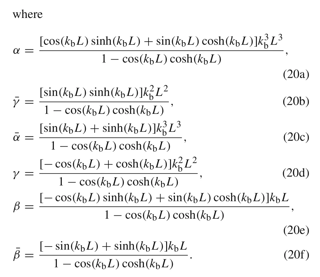
whereFbeis the equivalent nodal force vector of the beam associated with the distributed dynamic forces,Sb(s)is the spectral stiffness matrix of the beam element in the Laplace domain,they can be written as

whereQbe1,Mbe1,Qbe2,andMbe2are the equivalent nodal force components as shown in Fig.1.
One can obtainSb(s)by substituting the expression ofNbinto Eq.(18),after some simplification,as

2.2 Spectral rod element
The governing partial differential equation of motion for a uniform rod can be written in the following form

whereu(x,t)andfr(x,t)are the longitudinal displacement and the external force in the time domain,respectively.
The derivation for the spectral stiffness matrix of the rod element is analogous to that of the beam element.Thus,the result can be expressed directly as

whereFrbis the nodal force vector of the rod associated with the concentrated dynamic forces applied on the nodes,Frb=[Frb1Frb2]T,Frb1andFrb2are the nodal force components as shown in Fig.2.Freis the equivalent nodal force vector of the rod associated with the distributed dynamic forces,Sr(s)is the spectral stiffness matrix of the rod element,they can be written as


Fig.2 Nodal forces and displacements of a rod element in the Laplace domain

Fig.3 Nodal forces and displacements of a beam-column element in the Laplace domain

2.3 Spectral beam-column element
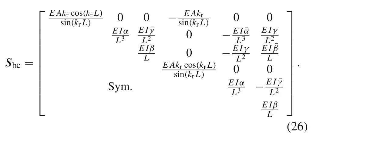
Complied with the assumption of the small elastic deformation in Sect.2,the nodal displacement vector of the spectral beam-column elementUbccan be related to the nodal force vectorFbcband the equivalent nodal force vectorFbcein the Laplace domain as

2.4 Equivalent nodal force of the moving load problem
According to the analysis at the beginning of Sect.2,the derivations are based on the model of the spectral beam element.The equivalent nodal forces of the spectral beamcolumn element can be obtained by extending the dimension.The specific derivation process is as follows

wheref(k)(xg,tg)is the external force of thekth element caused by the moving loadP(tg)in the global length and time coordinate.xgis the global length coordinate with the origin at the left-hand end of the whole beam as shown in Fig.4.tgis the global time coordinate with the origin at the instant of the moving load arriving upon the left-hand end of the whole beam.δis the Dirac delta function,cis the constant speed of the moving load motion,tk−1is the time cost when the moving load passes the precedingk–1 elements.Δtkis the time spent during the moving load passes thekth element.His the Heaviside function,it is defined as


Fig.4 The local length coordinate and the global length coordinate
The time cost when the moving load passes the precedingkelementstkcan be related toΔtkas

whereL jis the length of thejth element.
We define thatt(k)is the local time coordinate with the origin at the instant of the moving load arriving upon the left-hand end of thekth element of the whole beam,it can be expressed by

The differential oft(k)can be written as

The definition ofx(k)is the local length coordinate with the origin at the left-hand end of thekth element of the whole beam(see Fig.4),it can be related toxgin the following form


Based on Eqs.(29)and(30),one can obtain the relationship:

Substituting Eqs.(29),(30),(32),and(33)into Eq.(27),we can further express the external force in the local length and time coordinate of thekth element as

From Eqs.(30),(31),and(34),the external force of thekth element in the Laplace domainF(k)(x(k),s)can be written as

Asf(k)(x(k),t(k))=0 whent(k)<0,Eq.(35)can be equally expressed by

The result of the above integration is

whereu(k)=ct(k)is the position of the moving load in the local length coordinate.
Based on Eq.(17)and Eq.(37),we can obtain the equivalent nodal force vector of thekth elementFbe(k):

when 0≤x(k)<L k,we can obtain

Thus,substituting Eq.(39)into Eq.(38)gives

If the moving loadPdoes not change with the time and has a constant valueP0,then Eq.(40)can be simplified to the following form

In this work,all the calculation is based on the constant moving load.
3 Improved spectral element method
In Sect.3.1,we will investigate the influence of introducing the static Green function on the formulation of the spectral element.As the axial deformation and the bending deformation are decoupled,and the moving load works mainly on the beam model,so the derivation is based on the spectral beam model.Furthermore,according to the static Green function,the improved function is deduced in Sect.3.2.
3.1 Improved spectral beam element
Based on the method proposed by Pesterev et al.[28,29],the improved transverse displacement of a beam element in the time domainvI(x,t)is constructed as the following form

wherexrepresents the position in the local coordinate system andtrepresents the time.It should be noticed that Eq.(42)is established when the moving load is with the unit magnitude.vG(x,t)is the static Green’s function of the element,it represents the transverse displacement of the beam element with the unit static force on the positionct.It satisfies the following equation

The improved transverse displacementvI(x,t)can be transformed from the time domain to the Laplace domain.The transverse displacement in the Laplace domainVI(x,s)can be written as

For the clamped-clamped beam,the boundary conditions can be represented as the following form

The equation of motion of the beam element in the Laplace domain is given by

The nodal shear forces and bending moments of the beam element with the concentrated dynamic forces applied at the nodes can be expressed by
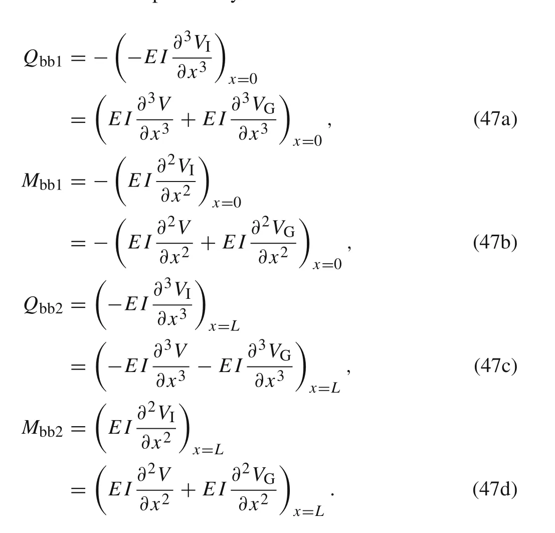
According to the weighted-integral method,the weak form of Eq.(46)can be written as

Substituting Eq.(44)into Eq.(48)leads to

whereFg(x,s)is the generalized force,it can be deduced by the following equation

The first term on the left side of Eq.(49)can be deduced as the following form by using the integration by parts:

By combining Eqs.(6),(14),(47)and(51),one can transform Eq.(49)to

Applying the integration by parts on Eq.(53),we have

From Eqs.(45),(52),(53),and Eq.(54),one can obtain

Substituting Eq.(8)into Eq.(55)gives

The dynamic shape function of the beam element can be deduced from the homogeneous form of Eq.(2),that is

From Eq.(57),Eq.(56)can be also expressed as

It can be seen that Eq.(15)and Eq.(58)is the same.It means that the static Green function have no effect on the derivation of the spectral beam element.Thus,one can calculate the nodal displacement vectorVb(s)by using the spectral stiffness matrix in Eq.(19)and the equivalent nodal force vectorFbein Eq.(41).The transverse displacement in the Laplace domainV(x,s)can be obtained by Eq.(8).The transverse displacement in the time domainv(x,t)can be obtained by using the inverse Laplace transformation.Finally,the improved transverse displacement in the time domainvI(x,t)can be calculated.
3.2 Improved function
The derivation in Sect.3.1 is based on the assumption that the constant moving loadP0is with the unit magnitude.In this section,due to the advantage of the P-method[28,29],we will deduce the improved function for thekth element of the whole beam in the global coordinate system and in the time domain whenP0is with any magnitudes.Hence,Eq.(43)can be rewritten in the following form

wherevG(k)(xg,tg)is the improved function for the transverse displacement of thekth element.
The boundary conditions are
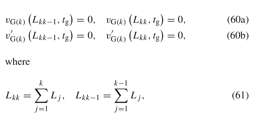
whereL kk−1=0 whenk=1.
Based on Eqs.(59)and(60),one can obtain the solution as the following form


where the Heaviside functions inside the last two square brackets are added,they are used to restrict the action time and position of the improved function,i.e.the function only works when the moving load passes thekth element and the length coordinate is in thekth element at the same time.
4 Application
4.1 One-span bridge
Vehicle-bridge interaction is an extensively studied moving load problem.It was believed that the collapse of Stephenson’s Bridge across River Dee at Chester in England in 1847 was caused by the dynamic effects of moving loads[31].Thus,it is necessary to carry out the research on the moving load problems in the bridge design.
For a one-span bridge subjected to the moving load,it can be considered as a beam structure with simply supported boundary condition.Figure 5 shows the beam model and the parameters used in the analysis are shown in Table 1.In this section,the transverse displacement,the bending moment and the shear force for this model will be investigated.Fryba[32]performed a systematically research on the vibration of a beam subjected to a variety of traveling loads.In order to validate the correctness of the method proposed in this work,the SEM and the improved SEM results will be compared with the analytical solution given in Ref.[32],and the availability of the improved SEM will be validated.The accuracy and the errors will be further discussed.
The pointAis a nodal point.The rotation of this point can be calculated by using only one spectral beam element(i.e.SEM1)without considering the improved function as shown in Fig.6.The exact result in Ref.[32]is expressed by the Fourier series.In the analytical solution,the first 1,2,and 4 term/terms is/are considered(i.e.1TS,2TS,and 4TS in Fig.6a),respectively.It can be seen that the analytical solutions converge to the SEM results when the number of terms become larger.This tendency displays the high accuracy of the nodal results calculated by the SEM owing to the exact dynamic shape function.Hence,one can adopt this approach to obtain the exact nodal displacement for the moving load problem.
As the exact solution of Ref.[32]is given by the Fourier series,we need to discuss the error with the increase of series terms in order to choose some specific term solution as the exact one.Figure 6b shows the relative error of different term solutions with respect to the 10 term solution whenxg=7.5 m andtg=L AB/2cs.It can be observed that the error decreases rapidly with the term increasing.When the term number is 4,the relative error is 0.099%.This error can be accepted in the calculation of this work.Thus,the 4 term solution will be seen as the analytic solution of the displacement hereinafter.
In Fig.7a,the displacement of the midpoint is calculated when the beam is equally divided to 1,3,5 spectral elements(i.e.SEM1,SEM3,and SEM5),respectively.What we want to emphasize is that the midpoint of the model in Fig.5 is not a node in the calculation.It can be observed that the one element results do not agree with the exact solution,but the displacement results show gradually better agreement with the analytic results with the mesh refinement.However,it will increase the amount of calculation.
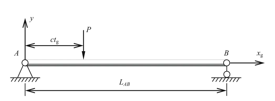
Fig.5 The model of one effective span of bridges subject to the moving load
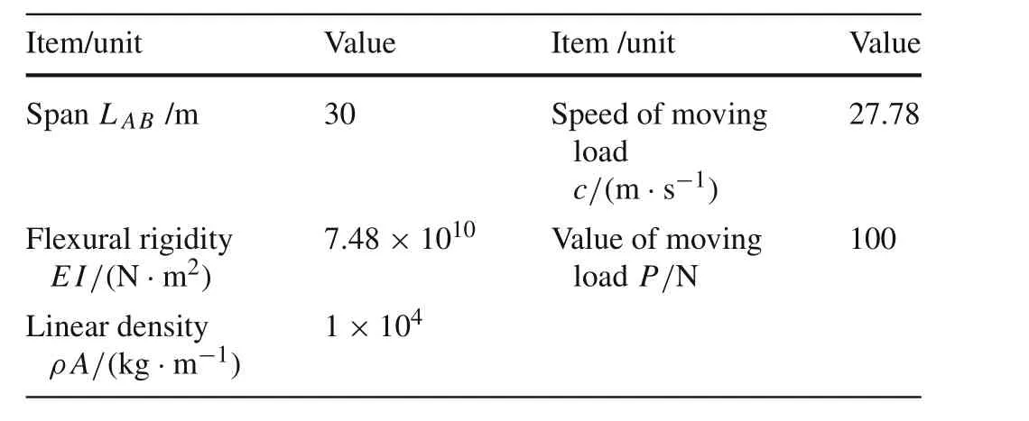
Table 1 Parameters of the bridge model
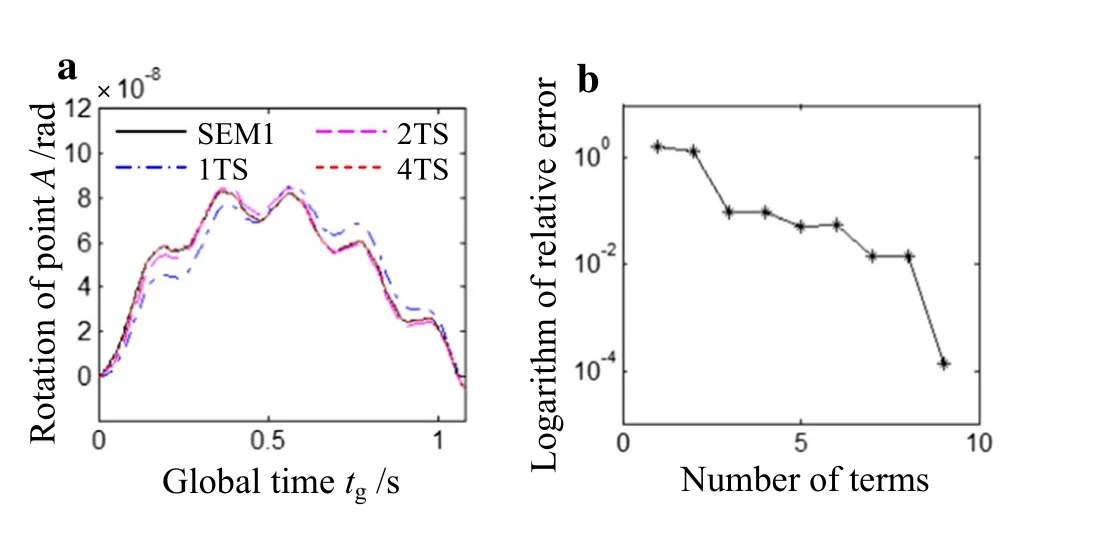
Fig.6 The rotation of point A for the model of one effective span of bridges subject to the moving load and the relative error of different term solutions when xg=7.5 m and tg=L AB/2c s.a The rotation of point A.b Logarithm of relative error
Based on the model in Fig.5,we further calculate the bending moment and the shear force of the midpoint with 1,3,5 spectral beam elements(i.e.SEM1,SEM3,and SEM5),respectively.Considering the different rate of convergence of the analytic solution for the displacement,the bending moment and the shear force,we choose the 50 term solution and the 500 term solution as the exact results of the bending moment and the shear force,respectively.For more details about the convergence rate of the series solution,one can refer to Ref.[32].From Fig.7b,c,it can be found that neither the bending moment nor the shear force can agree with the exact solution using only one element.Even the mesh is refined,the convergence rate is not as fast as that of the displacement,this means more elements need to be used to simulate and solve the problem.But,if this were done,the total degree of freedom and the calculation difficulty would increase.

Fig.7 The displacement,the bending moment and the shear force of midpoint using 1,3,5 spectral beam elements,respectively.a The displacement.b The bending moment.c The shear force

Fig.8 The bending moment and the shear force of midpoint using 2,4 spectral beam elements,respectively.a The bending moment.b The shear force
From the analysis result of Fig.7,it can be concluded that the moving load problem cannot be simulated and solved with only one spectral element for non-nodes.Then,we obtain the bending moment and the shear force of the midpoint with 2 and 4 spectral beam elements(i.e.SEM2 and SEM4),respectively.In these two situations,the midpoint is the node,and the results are shown in Fig.8.It can be seen that the results still do not agree with the exact solutions although they are from the node.
Figure 9 a shows the displacement of the midpoint obtained by only one spectral element with considering the improved function(i.e.ISEM1).It can be observed that the displacement agrees with the exact solution well.Accordingly,the correctness and the efficiency of the improved spectral element method in this work are proved.
Figure 9b shows the relative error of the midpoint displacement with respect to the exact solution.It can be seen that the relative error in most time period is smaller than 0.1%,however,during the beginning 0.075 s and the last 0.039 s the relative error is larger than 10%.There are two reasons for this phenomenon.First,the “exact”solution in this work is approximated by 4 terms of the analytic result,and this treatment causes some error which is very small.Second,from the result of the absolute error in Fig.9c,one can find that the absolute errors are in the same order of magnitude,i.e.the large relative error in some period is not caused by the absolute error but due to the small absolute value of the exact solution.Thus,the result of displacement in a quite small time period at the beginning and the end cannot be used if there is a strict requirement on the relative error.

Fig.9 The displacement of midpoint using 1 improved spectral beam element,the relative error and the absolute error of the midpoint dis placement result with respect to the exact solution.a The displacement.b Logarithm of relative error.c The absolute error
Furthermore,one can obtain the bending moment and the shear force of the midpoint considering the improved function,which is shown in Fig.10.It should be mentioned that only one improved spectral element is used in the calculation.Compared with the method in Ref.[33],the method in this work is more efficient for the calculation because four elements at least are needed in Ref.[33].Based on the figure,one can see that the results in this work agree with the exact solutions well although the bending moment and the shear force have higher differential orders by comparing with the displacement.
The errors relative to the exact solution for the bending moment and the shear force are calculated as shown in Fig.11.Similar analysis results as that of the displacement can be obtained.For most time period,the relative error of the bending moment is smaller than 0.1%,and that of the shear force is smaller than 1%.From Fig.11b,one can observe that the relative error at0.54 sis much larger than others.The reason is that the moving load is acting on the midpoint at this moment,the shear force is experiencing the sudden change in the direction,a little absolute error can cause a much larger relative error.Hence,the result of the shearforce at this point cannot be used.Still,the precision of the results calculated by considering the improved function as a whole can meet the requirement in engineering.

Fig.10 The bending moment and the shear force of midpoint using 1 improved spectral beam element.a The bending moment.b The shear force

Fig.11 The relative error of the bending moment and the shear force result with respect to the exact solution.a The bending moment.b The shear force
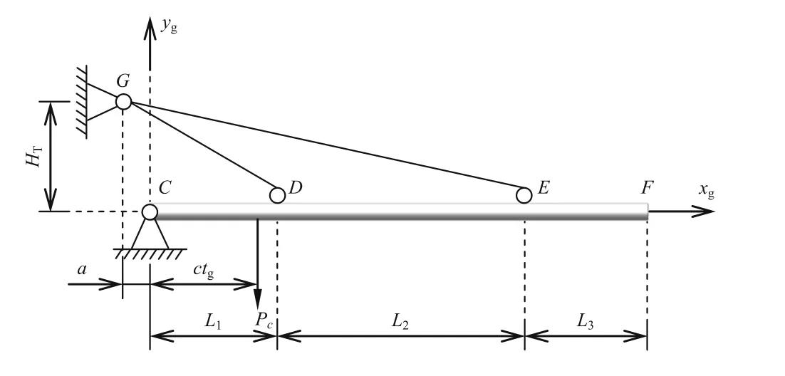
Fig.12 The calculation model of the twin-lift jib of the tower crane
4.2 Horizontal jib of tower crane
The structural vibration caused by moving loads is one of the most significant topics in the design of tower cranes.Compared with static loads,a moving load will produce larger deflections and higher stresses, which will cause the stiffness and the stability problems. Hence, the moving load problem must be considered in the structural design of the tower crane.The horizontal jib of tower crane is a typical structure subject to the moving load.Figure 12 shows the calculation model of the twin-lift jib which is subject to a constant moving loadPc.The structural parameters for the initial model are shown in Table 2.
For the initial model,each jib part(i.e.CD,DE,andEFin Fig.12,respectively)is simulated by means of one spectral beam-column element with considering the improved function.The two jib ties(i.e.GDandGEin Fig.12)are simulated by one spectral rod element,respectively.The dynamic deflection of the jib is calculated when the global timetg=30 s as shown in Fig 13a.In order to prove the correctness of the procedure for this calculation,we also calculate the result using the FEM with 5,10,200 elements for each jib part(i.e.FEM5,FEM10,FEM200),respectively.Because the FEM has long been considered as a powerful tool to validate the correctness of new methods[34,35].From Fig.13a,one can observe that the FEM result converge to that of this work with the mesh refinement.Especially,when each part of the jib is simulated by 200 elements of the FEM,the result nearly agrees with that of this work.Based on the convergence trend of the FEM results,one can confirm that the procedure is correct.
Furthermore,when the global time is 30 s we verify the correctness of the procedures for the calculation of the bending moment and the shearforce using the conventional FEM,in which each jib component is divided into 5,10,200 ele-ments,respectively.The results are shown in Fig.13b,c.The improved function is considered in the calculation using the method of this work.It can be observed that the convergent rate of the shear force calculated by the FEM is not as fast as that of the bending moment,and the convergent rate of the shear force is slower because its order of derivative is higher.This means more elements need to be used in the FEM,it will increases the amount of calculation,but the corresponding results obtained by the method proposed in this work uses only one improved spectral element for each part.
Figure 14a shows the influence of the moving load speedcon the displacement.Based on the initial model,the dynamic deflection of the jib at the middle moment is calculated when the speed is 1,50,80,100 m/s,respectively.From Fig.14a,one can see that the dynamic deflection of the whole jib decreases with the increase of the moving speedc,but the curvature of the deflection increases.This can accelerate the fatigue failure of the structural components,so the minimum speed of the moving load within the requirement should be used in the process of operation.
Then,the effect of the moving load speedcon the bending moment and the shear force are shown in Fig.14b,c,respectively.At the middle moment,the moving load is acting on the midpoint of the jib(i.e.the midpoint of the middle part of the jibDEin Fig.12).There is no moving load acting on the inner and the outer part of the jib(i.e.CDandEFin Fig.12,respectively)at the moment.According to Fig.14b,it can be observed that the absolute value of the bending moment inCDdecreases as the speed increases,and that inEFincreases.However,for the part the moving load acting on(i.e.whenxgis between 15 m and 45 min Fig.14b),the bending moment is larger as a whole when the speed is 80 m/s but 100 m/s.This means if the load moves in some special speed,the structural part applied by the load will bear a larger bending moment.Thus,one should avoid this moving speed.As can be seen in Fig.14c,similar analysis conclusions can be obtained from the shear force results.
Figure 15a shows the effect of the inertia moment on the dynamic deflection of the jib.One can see that the dynamic deflection of the jib decreases as the moment of inertia increases.So we can control the dynamic deflection by improving the moment of inertia in the structural design.Figure 15b,c shows the effect of the inertia moment on the bending moment and the shear force,respectively.From Fig.15b,it can be found that there is no obvious influence of the inertia moment on the bending moment as a whole,although the absolute value of the bending moment in the inner part of the jib experiences a small increase as the inertia moment increases.For the shear force,similar analysis result can be obtained from Fig.15c.

Table 2 The parameters of the initial twin-lift jib model

Fig.13 The dynamic deflection,the bending moment and the shear force of the jib at tg=30 s for the initial model.a The dynamic deflection.b The bending moment.c The shear force

Fig.14 The dynamic deflection,the bending moment and the shear force of jib at the middle moment when the speed of the moving load is 1,50,80,100 m/s,respectively.a The dynamic deflection.b The bending moment.c The shear force

Fig.15 The dynamic deflection,the bending moment and the shear force of the jib at tg=30 s when the moment of inertia is 0.01,0.02,0.1,0.21 m4,respectively.a The dynamic deflection.b The bending moment.c The shear force

Fig.16 The dynamic deflection,the bending moment and the shear force of the jib at tg=30 s when the moving load is 10,000,20,000,50,000,100,000 N,respectively.a The dynamic deflection.b The bending moment.c The shear force
Figure16 shows the results of the dynamic deflection,the bending moment and the shearforce of the jib when the moving load is 10,000,20,000,50,000,and 100,000 N,respectively.It can be observed that the effect of the moving load magnitude on the dynamic deflection,the bending moment and the shear force of the jib is obvious,they all increase dramatically as the magnitude of the moving load increases.
5 Conclusions
In this paper,the spectral stiffness matrices of the beam and the rod are constructed in accordance with the LT theory and the variational method.The spectral stiffness matrix of the beam-column element is obtained by superimposing the stiffness-matrix results of the rod and the beam.It is found that the introduction of the static Green function on the formulation of the spectral element has little influence.In addition,the improved function is deduced based on the P-method.The main findings from this work are as follows
(1)Compared with the exact solution,the method proposed in the present work can be used to determine the dynamic deflections,bending moments and shear forces associated with the moving load problem with extremely high-precision.In most cases,the relative errors are smaller than 1%.Thus,it can be used with confidence for structural design by engineers.
(2)In comparison to FEM,the method achieves the same level of results by using a smaller number of elements.Moreover,the method can be widely used for statically determinate as well as statically indeterminate structures.
(3)The dynamic deflections of twin-lift jibs decreases with increases in moving load speeds,the deflection curvatures,on the other hand,increase.Further,if the load moves at a certain special speed,the structural component applied by the load will bear a larger bending moment and shear force.
(4)As the moments of inertia of the jib’s components increase,the dynamic deflections decrease.Overall,there are no noticeable influences of the inertia moment on the bending moment and the shear force.
(5)The effects of the moving load magnitude on the dynamic deflection,the bending moment and the shear force all increase as the magnitude of the moving load increases.
Overall,the method and the results presented in this paper are expected to be useful for addressing the moving load problem arising in structural design.
AcknowledgementsThe project was supported by the National Key Technology R&DProgram(Grant2011BAJ02B01-02)and the National Natural Science Foundation of China(Grant 11602065).
1.Yau,J.D.,Yang,Y.B.,Kuo,S.R.:Impact response of high speed rail bridges and riding comfort of rail cars.Eng.Struct.21,836–844(1999)
2.Wu,Y.S.,Yang,Y.B.:Steady-state response and riding comfort of trains moving over a series of simply supported bridges.Eng.Struct.25,251–265(2003)
3.Konstantakopoulos,T.G.,Raftoyiannis,I.G.,Michaltsos,G.T.:Suspended bridges subjected to earthquake and moving loads.Eng.Struct.45,223–237(2012)
4.Fu,S.,Cui,W.:Dynamic responses of a ribbon floating bridge under moving loads.Mar.Struct.29,246–256(2012)
5.Boschetti,G.,Caracciolo,R.,Richiedei,D.,et al.:Moving the suspended load of an overhead crane along a pre-specified path:a non-time based approach.Robot.Comput.Integr.Manuf.30,256–264(2014)
6.Yang,W.,Zhang,Z.,Shen,R.:Modeling of system dynamics of a slewing flexible beam with moving payload pendulum.Mech.Res.Commun.34,260–266(2007)
7.Karttunen,A.T.,Hertzen,R.:Dynamic response of a cylinder cover under a moving load.Int.J.Mech.Sci.82,170–178(2014)
8.Dyniewicz,B.:Space-time finite element approach to general description of a moving inertial load.Finite Elem.Anal.Des.62,8–17(2012)
9.Kidarsa,A.,Scott,M.H.,Higgins,C.C.:Analysis of moving loads using force-based finite elements.Finite Elem.Anal.Des.44,214–224(2008)
10.Nguyen,V.H.,Duhamel,D.:Finite element procedures for nonlinear structures in moving coordinates.Part 1:infinite bar under moving axial loads.Comput.Struct.84,1368–1380(2006)
11.Nguyen,V.H.,Duhamel,D.:Finite element procedures for nonlinear structures in moving coordinates.Part II:infinite beam under moving harmonic loads.Comput.Struct.86,2056–2063(2008)
12.Yang,B.,Tan,C.A.,Bergman,L.A.:Direct numerical procedure for solution of moving oscillator problems.J.Eng.Mech.126,462–469(2000)
13.Yang,Y.B.,Lin,C.L.,Yau,J.D.,et al.:Mechanism of resonance and cancellation for train-induced vibrations on bridges with elastic bearings.J.Sound Vibr.269,345–360(2004)
14.Doyle,J.F.,Farris,T.N.:A spectrally formulated finite element for flexural wave propagation in beams.Int.J.Anal.Exp.Modal Anal.5,99–107(1990)
15.Doyle,J.F.:Wave Propagation in Structures:Spectral Analysis Using Fast Discrete Fourier Transforms,2nd edn.Springer,New York(1997)
16.Hong,M.,Park,I.,Lee,U.:Dynamics and waves characteristics of the FGM axial bars by using spectral element method.Compos.Struct.107,585–593(2014)
17.Nanda,N.,Kapuria,S.,Gopalakrishnan,S.:Spectral finite element based on an efficient layerwise theory for wave propagation analysis of composite and sandwich beams.J.Sound Vib.333,3120–3137(2014)
18.Wu,Z.J.,Li,F.M.,Wang,Y.Z.:Vibration band gap behaviors of sandwich panels with corrugated cores.Comput.Struct.129,30–39(2013)
19.Lee,U.:Equivalent continuum representation of lattice beams:spectral element approach.Eng.Struct.20,587–592(1998)
20.Lee,U.:Spectral Element Method in Structural Dynamics.Wiley,Singapore(2009)
21.Santos,E.R.O.,Arruda,J.R.F.,Dos Santos,J.M.C.:Modeling of coupled structural systems by an energy spectral element method.J.Sound Vib.316,1–24(2008)
22.Lee,U.:Dynamic characterization of the joints in a beam structure by using spectral element method.Shock Vib.8,357–366(2001)
23.Wang,Y.Z.,Li,F.M.,Huang,W.H.,et al.:The propagation and localization of Rayleigh waves in disordered piezoelectric phononic crystals.J.Mech.Phys.Solids 56,1578–1590(2008)
24.Wang,Y.Z.,Li,F.M.,Huang,W.H.,et al.:Wave band gaps in two dimensional piezoelectric/piezomagnetic phononic crystals.Int.J.Solids Struct.45,4203–4210(2008)
25.Wu,Z.J.,Li,F.M.:Spectral element method and its application in analysing the vibration band gap properties of two-dimensional square lattices.J.Vib.Control 22,710–721(2016)
26.Wu,Z.J.,Li,F.M.,Zhang,C.:Vibration band-gap properties of three-dimensional Kagome lattices using the spectral element method.J.Sound Vib.341,162–173(2015)
27.Wen,S.R.,Lu,N.L.,Wu,Z.J.:Dynamic property analysis of the space-frame structure using the spectral element method.Waves Random Complex Media 24,404–420(2014)
28.Pesterev,A.V.,Tan,C.A.,Bergman,L.A.:Anew method for calculating bending moment and shear force in moving load problems.J.Appl.Mech.Trans.ASME 68,252–259(2001)
29.Pesterev,A.V.,Bergman,L.A.:An improved series expansion of the solution to the moving oscillator problem.J.Vib.Acoust.Trans.ASME 122,54–61(2000)
30.Bathe,K.J.:Finite Element Procedures.Prentice Hall,Upper Saddle River(1996)
31.Ouyang,H.J.:Moving-load dynamic problems:a tutorial(with a brief overview).Mech.Syst.Signal Proc.25,2039–2060(2011)
32.Frýba,L.:Vibration of Solids and Structures Under Moving Loads,3rd ed.Thomas Telford Ltd.,London(1999)
33.Lou,P.,Au,F.T.K.:Finite element for mulae for internal forces of Bernoulli–Euler beams under moving vehicles.J.Sound Vib.332,1533–1552(2013)
34.Lian,Y.P.,Zhang,X.,Liu,Y.:An adaptive finite element material point method and its application in extreme deformation problems.Comput.Meth.Appl.Mech.Eng.241–244,275–285(2012)
35.Palma,R.,Pérez-Aparicio,J.L.,Taylor,R.L.:Non-linear finite element formulation applied to thermoelectric materials under hyperbolic heat conduction model.Comput.Meth.Appl.Mech.Eng.213–216,93–103(2012)
- Acta Mechanica Sinica的其它文章
- Motion of the moonlet in the binary system 243 Ida
- Adaptive ANCF method and its application in planar flexible cables
- Analytical modeling and simulation of porous electrodes:Li-ion distribution and diffusion-induced stress
- Macro and micro mechanics behavior of granite after heat treatment by cluster model in particle flow code
- Effect of a viscoelastic target on the impact response of a flat-nosed projectile
- Highly accurate symplectic element based on two variational principles

