A semi-analytical solution for electric double layers near an elliptical cylinder
Xiaoyun Dai·Zhenghua Qian·Jiashi Yang
1 Introduction
When a charged conductor(electrode)is brought in contact with a solid or liquid ionic conductor(electrolyte),the electrode repels or attracts the positive or negative ions in the ionic conductor.Thus,a thin ionic layer,called the electric double layer(EDL),near the electrode is formed[1].The redistribution of free ions and the formation of EDLs in ionic conductors can also be caused by the presence of charged particles or microemulsion droplets in a liquid.Accurate predictions of EDLs are fundamentally important in many applications such as ionic energy-storage systems and electrowetting devices[2],and ionic capacitors[3–5].The literature on EDLs is abundant.Many references can be found in the systematic reviews in Refs.[6,7].This paper is concerned with theoretical studies on EDLs and the geometry ofthe electrodes in particular.Various applications involving EDLs are associated with all kinds of electrode geometries.Theoretical results on EDLs have been obtained for a few geometrically perfect electrodes such as infinite plates[8–12],spheres[13,14],circular cylinders[15,16],and rods[17].There also exist limited studies on more complex electrode geometries,e.g.,porous electrodes and electrode roughness[18,19].More complicated electrodes such as comb[20–22]or interdigital electrodes[23]are also used in applications involving ionic conductors and EDLs.
In this paper,we perform a theoretical analysis on the EDL near an infinite cylinder with an elliptical cross section,which from the theoretical point of view,is fundamental in that it can reduce to other electrodes such as a circular cylinder or a thin plate as special cases.The equilibrium or motion of the ions in ionic conductors and EDLs are governed by the electric field and diffusion due to concentration gradients.There is a series of theoretical models with different levels of sophistication for modeling EDLs.The Helmholtz model consists of concentrated charge layers with zero thickness.We use the Gouy–Chapman theory[1],which describes a diffusive layer with an effective finite thickness.The Gouy–Chapman theory is nonlinear.For low values of the electric potential,which we assume in the present paper,the theories can be linearized[1].
2 Governing Equations
Consider the infinite elliptical metal conductor cylinder in an ionic conductor in Fig.1,which shows the cross section.The axis of the cylinder is along thezaxis determined fromxandyby the right-hand rule.
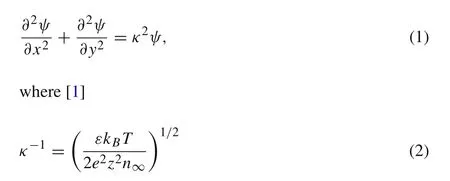
Within electrostatics,the electric potential on the ideal conductor cylinder is a constant.According to the linearized Gouy–Chapman theory[1],for a symmetric ionic conductor in which the cations and anions have the same properties and behaviors except that they carry opposite charges,the electric potentialψin the ionic conductor is governed by

is the Debye length,a combination of relevant material constants and a property of the ionic conductor.εis the dielectric constant.k Bis the Boltzmann constant.Tis the absolute temperature.eis the elementary charge.zis the ion valency.n∞is the ion number concentration atψ=0.The boundary condition on the elliptical surface of the cylinder isψ=V,a prescribed voltage,which is a constant.At infinity,we haveψ=0.Onceψis obtain from Eq.(1)and the boundary conditions,the ion concentrations are determined from[1]


Fig.1 An elliptical cylinder in an ionic conductor
wheren±are for cations and anions,respectively.For low values of the electric potential,Eq.(3)can be approximately linearized as

3 Semi-analytical solution
Since the boundary of the domain occupied by the ionic conduction is elliptical,we introduce the following elliptical coordinates(ξ,η)defined by


In elliptical coordinates,the solution to Eq.(1)is known.Considering the symmetry in the problem under consideration,the general solution to Eq.(1)can be written as


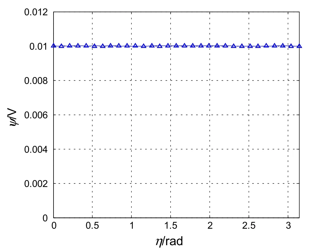
Fig.2 Potential distribution along the elliptical boundary calculated from thirty terms in the series

Table 1 Electric potential in the domain of the ionic conductor

Fig.3 a Electric potential;b n+/n∞ calculated from Eq.(3);c n−/n∞ calculated from Eq.(3);d E x= −dψ/d x;e E y= −dψ/d y;f E=(E2x+E2y)1/2

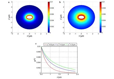
Fig.4 Effect ofκ−1:a Electric potential distribution whenκ−1=0.5μm;b electric potential distribution whenκ−1=1.5μm;c electric potential along the x axis when κ−1=0.5,1,1.5μm,respectively
whereAmare undetermined constants,cem(η,q)are Mathieu functions,M c(3)m(ξ,q)are modified Mathieu functions[24],and

Equation(7)automatically satisfied the boundary condition thatψ=0 at infinity.On the elliptical boundary of the cylinder in Fig.1,the boundary condition requires that

which defines a system of linear algebraic equations forAm.These linear equations are solved numerically by the collocation method,i.e.,the equations are satisfied at a series of chosen points on the elliptical boundary.The number of chosen points can be increased to achieve any desired accuracy.
4 Numerical results and discussion
As a numerical example,we consider the case whena=0.5μm,b=0.3μm,κ−1=1μm,andV=0.01 V.In this casec=0.4μm.The elliptical boundary is determined from sinhξ0=b/c=0.75,orξ0=0.6931.To examine how well the boundary condition in Eq.(9)is satisfied by the collocation method,30 terms in the series in Eqs.(7)or(9)were kept and,correspondingly,30 points on the elliptical boundary were used to enforce Eq.(9)and determine the coefficients in the truncated series.The potential distribution along the elliptical boundary is shown in Fig.2.Clearly,Eq.(9)is well satisfied on the elliptical boundary.
To examine the convergence in the domain of the ionic conductor,we calculated the electric potential in the ionic conductor using 20 and 30 terms in the series in Eq.(7).The results are shown in Table 1 for different points in the ionic conductor.Because of symmetry,only the domain with 0≤η≤ π/2 is shown whileξranges from very close to the elliptical boundary to more than twice the semi-major axis of the elliptical boundary where the potential has dropped significantly.It can be seen from Table 1 that within four significant figures,the series in Eq.(7)produces the same result for the electric potential whether 20 or 30 terms are kept.
Figure 3 shows the basic fields whena= 0.5μm,b=0.3μm,κ−1=1μm,andV=0.01 V.Figure 3a is the electric potential.It varies rapidly near the elliptical boundary.A sufficiently large domain is chosen to plot the potential field and to show that the potential is nearly uniform at the far field.The ion concentrations in Fig.3b,c were calculated from Eq.(3)usingz=1 andT=300 K.Since the voltage at the elliptical boundary is positive,the positive ions are expelled from the electrode and the negative ions are attracted to it as expected.If the approximated ion concentrations in Eq.(4)are used,the results look qualitatively similar to Fig.3b,c,but there is a maximal error of 9.7%because in this casezeψ/(kBT)=0.3867,not very small and hence the approximation in Eq.(4)is not very accurate.The electric field components,E xandE y,are shown in Fig.d,e,respectively.At the ends of the semi-major and semi-minor axes,there are concentrations ofE xandE y,respectively.Sincea>b,E xis more concentrated thanE y.It can be seen from the magnitude of the electric fieldE=(E2x+E2y)1/2in Fig.3f that the maximal concentration ofEis at the ends of the semi-major axis.
Figure 4 shows the effect ofκ−1on the electric potential distribution.a=0.5μm,b=0.3μm,andV=0.01 V were kept the same as those used for plotting Fig.3,whileκ−1was changed to 0.5 and 1.5μm,respectively.From Figs.4a,b and 3a,asκ−1increases,the electric potential distribution becomes more spread.It can be seen thatκ−1is a good measure of the EDL thickness in which the potential varies significantly.For a closer look,the potential distribution along thexaxis for different values ofκ−1is shown in Fig.4c.For smaller values ofκ−1,the electric potential changes more rapidly,indicating stronger electric field concentrations near the ends of the semi-major axis.

Fig.5 Effect of b:a electric potential distribution when b=0.1μm;b electric potential distribution when b=0.01μm;c electric potential along the x axis when b=0.3,0.1,0.01μm,respectively
Figure 5 shows the effect ofb,the semi-minoraxis,on the electric potential distribution.a=0.5μm,κ−1=1μm,andV=0.01 V were kept the same as those used in Fig.3,whilebwas reduced to 0.1 and 0.01μm,respectively.In the case ofb=0.01μm,the elliptical cylinder effectively reduces to a plate finite in thexdirection for which we were not able to find a theoretical solution for its EDL in the literature.Figuresa,a,b show that asbdecreases,the electric potential distribution and hence the ion concentrations follow the elliptical boundary in the sense that they always change rapidly near the elliptical boundary and are nearly uniform at the far field.Figurec shows that for smallbthe electric potential changes more rapidly along thexaxis near the ends of the semi-major axis.This implies a largerE xthere and hence more electric field concentration there.
5 Conclusion
The semi-analytical solution obtained can produce sufficiently accurate results for the fields caused by an electric potential on an elliptical cylinder which includes a circular cylinder and a finite plate as special cases.The potential distribution and the ion concentrations are qualitatively similar in that they all vary rapidly near the elliptical boundary and are nearly uniform at the far field.κ−1is a good measure of the EDL thickness.The electric field shows concentrations at the ends of the semi-major and semi-minor axes of the ellipse.The highest concentrations are at the ends of the semi-major axis.These concentrations are more pronounced whenκ−1decreases or when the semi-minor axis decreases while the semi-major axis is fixed.
Acknowledgements This work was supported by the National Natural Science Foundation of China(Grants 11502108 and 11232007),the Program for New Century Excellent Talents in Universities(Grant NCET-12-0625),the Natural Science Foundation of Jiangsu Province(Grant BK20140037),the Fundamental Research Funds for Central Universities(Grant NE2013101),and a project Funded by the Priority Academic Program Development of Jiangsu Higher Education Institutions(PAPD).
1.Masliyah,J.H.,Bhattacharjee,S.:Electrokinetic and Colloid Transport Phenomena,Chap.5.Wiley,New York(2006)
2.Kornyshev,A.A.:Double-layer in ionic liquids:paradigm change?J.Phys.Chem.B 111,5545–5557(2007)
3.Sampath,S.,Choudhury,N.A.,Shukla,A.K.:Hydrogelmembrane electrolyte for electrochemical capacitors.J.Chem.Sci.121,727–734(2009)
4.Kalupson,J.,Ma,D.,Randall,C.A.,etal.:Ultrahigh-power flexible electrochemical capacitors using binder-free single-walled carbon nanotube electrodes and hydrogel membranes.J.Phys.Chem.C 118,2943–2952(2014)
5.Syahidah,S.N.,Majid,S.R.:Ionic liquid-based polymer gel electrolytes for symmetrical solid-state electrical double layer capacitor operated at different operating voltages.Electrochim.Acta 175,184–192(2015)
6.Bazant,M.Z.,Thornton,K.,Ajdari,A.:Diffuse-charge dynamics in electrochemical systems.Phys.Rev.E 70,02150(2004)
7.Lockett,V.,Horne,M.,Sedev,R.,etal.:Differential capacitance of double layer at the electrode/ionic liquids interface.Phys.Chem.Chem.Phys.12,12499–12512(2010)
8.Golovnev,A.,Trimper,S.:Exact solution of the Poisson–Nernst–Planck equations in the linear regime.J.Chem.Phys.131,114903(2009)
9.Golovnev,A.,Trimper,S.:Analytical solution of the Poisson–Nernst–Planck equations in the linear regime at an applied dcvoltage.J.Chem.Phys.134,154902(2011)
10.Golovnev,A.,Trimper,S.:Analytical solution of the PNPequations at AC applied voltage.Phys.Lett.A 376,1391–1395(2012)
11.Brown,M.A.,Bossa,G.V.,May,S.:Emergence of a Stern layer from the incorporation of hydration interactions into the Gouy–Chapman model of the electrical double layer.Langmuir 31,11477–11483(2015)
12.Trefalt,G.,Behrens,S.H.,Borkovec,M.:Charge regulation in the electrical double layer:ion adsorption and surface interactions.Langmuir 32,380–400(2016)
13.Goel,T.,Patra,C.N.:Structure of spherical electric double layers:a density functional approach.J.Chem.Phys.127,034502(2007)
14.López-García,J.J.,Aranda-Rascón,M.J.,Horno,J.:Electrical double layer around a spherical colloid particle:the excluded volume effect.J.Colloid Interface Sci.316,196–201(2007)
15.Tseng,S.,Jiang,J.M.,Hsu,J.P.:Electrical potential in a cylindrical double layer:a functional theory approach.J.Colloid Interface Sci.273,218–223(2004)
16.Goel,T.,Patra,C.N.,Ghosh,S.K.,et al.:Structure of cylindrical electric double layers:a systematic study by Monte Carlo simulations and density functional theory.J.Chem.Phys.129,154906(2008)
17.Halle,B.:Orientation-dependent electrical double-layer interactions:I.Rodlike macroions of finite length.J.Chem.Phys.102,7238–7250(1995)
18.Iozzo,D.A.B.,Tong,M.,Wu,G.,et al.:Numerical analysis of electric double layer capacitors with mesoporous electrodes:effects of electrode and electrolyte properties.J.Phys.Chem.C 119,25235–25242(2015)
19.Singh,M.B.,Kant,R.:Theory of anomalous dynamics of electric double layer at heterogeneous and rough electrodes.J.Phys.Chem.C 118,5122–5133(2014)
20.Xie,J.,Agarwal,R.,Liu,Y.,et al.:A three-axis SOI accelerometer sensing with both in-plane and verticalcomb electrodes.Microsyst.Technol.18,325–332(2012)
21.Surapaneni,R.,Guo,Q.,Xie,Y.,et al.:A three-axis high-resolution capacitive tactile imagersystem based on floating comb electrodes.J.Micromech.Microeng.23,075004(2013)
22.Molina-Lopez,F.,Briand,D.,Rooij,N.F.D.:Decreasing the size of printed comb electrodes by the introduction of a dielectric interlayer for capacitive gas sensors on polymeric foil:modeling and fabrication.Sensors Actuat.B Chem.189,89–96(2013)
23.Ngo,T.T.,Shirzadfar,H.,Bourjilat,A.,et al.:A method to determine the parameters of the double layer of a planar interdigital sensor.In:Proceedings of the8th International Conference on Sensing Technology,Liverpool,348–351(2014)
24.McLachlan,N.W.:Theory and Application of Mathieu Functions.Oxford Press,Oxford(1951)
- Acta Mechanica Sinica的其它文章
- Amplitude modulation and extreme events in turbulent channel flow
- The influence of surface roughness on cloud cavitation flow around hydrofoils
- The influence of sub-grid scale motions on particle collision in homogeneous isotropic turbulence
- A simple algorithm to improve the performance of the WENO scheme on non-uniform grids
- Third-order polynomial model for analyzing stickup state laminated structure in flexible electronics
- High-precision solution to the moving load problem using an improved spectral element method

