Experimental study on piping in sandy gravel foundations considering effect of overlying clay
Shung Wng*,Jin-sheng Chen,Hi-qing HeWen-zheng He
aCollege of Civil and Transportation Engineering,Hohai University,Nanjing 210098,China
bCollege of Earth Sciences and Engineering,Hohai University,Nanjing 210098,China
Received 8 April 2015;accepted 10 August 2015
Available online 15 June 2016
Experimental study on piping in sandy gravel foundations considering effect of overlying clay
Shuang Wanga,*,Jian-sheng Chenb,Hai-qing Hea,Wen-zheng Hea
aCollege of Civil and Transportation Engineering,Hohai University,Nanjing 210098,China
bCollege of Earth Sciences and Engineering,Hohai University,Nanjing 210098,China
Received 8 April 2015;accepted 10 August 2015
Available online 15 June 2016
Abstract
Theinfluenceoftheoverlyingclayontheprogressionofpipinginthesandygravelfoundationofwater-retainingstructuresisoftenneglected.In order tostudy this influence,an experimental investigation was conducted on a laboratory-scale model.It was discovered that the critical hydraulic gradientandtheareaofthepipingtunnelincreasewhentheoverlyingclaythickens.Withathickerclaylayer,erosionofthesandygravelbelowthe claylayeroccurslater,but,oncetheerosionstarts,theerosionrateisveryhighandtheaveragevelocityofwaterseepingthroughthecross-sectionof the sandy gravel increases rapidly due to the low deformability of the thick clay layer.Furthermore,it was found that the progression of piping is a complicatedanditerativeprocessinvolvingerosionoffineparticles,cloggingofpores,andflushingofthecloggedpores.Twotypesoferosionhave been identified in the progression of piping:one causes the tunnel to advance upstream,and the other increases the depth of the tunnel.The results show that the overlying clay is an important factor when evaluating piping in sandy gravel foundations of water-retaining structures.
©2016 Hohai University.Production and hosting by Elsevier B.V.This is an open access article under the CC BY-NC-ND license(http:// creativecommons.org/licenses/by-nc-nd/4.0/).
Piping;Experimental model;Sandy gravel foundation;Overlying clay;Clog;Erosion rate
1.Introduction
Piping or tunnel erosion,defined as the hydraulic removal of subsurface soil,causing the formation of underground channels in natural landscapes(Boucher,1990),is an important cause of dam failure.Recent comprehensive reviews by Foster et al.(2000a,2000b)and Fell et al.(2003)showed that internal erosion and piping are the main causes of dam failure, with the proportion of dam failures caused by piping increasing from 43%before 1950 to 54%after 1950.In reanalyzing this survey data,Richards and Reddy(2008) determined that approximately 31% of all dam failures resulted from the piping mode of failure.
Since an embankment consists of different zones and materials,a wide range of parameters may influence initiation and continuation of an internal erosion process.The properties of materials,integrity of the structure,cross-sectional geometry of the dam embankment,and groundwater flow properties are some of the relevant parameters.Of the properties of materials,the grain size distribution and microstructure of the soil have significant influence on the potential of erosion,an issue that has been investigated by numerous researchers(Fannin and Moffat,2006;Wan and Fell,2008;Indraratna et al., 2011).It is generally accepted that broadly graded soils with flat slopes in the fine fraction and steep slopes in the coarse fraction and gap-graded granular soils are often internally unstable.Li(2008)proposed that the initiation of the internal erosion process was also influenced by the porosity of soil and grain shape.Al-Riffai and Nistor(2010)showed that the compaction of an earthfill dam model had a significant influence on internal erosion.
Bendahmane et al.(2008)performed a parametric study to examine the influence of three critical parameters(hydraulicgradient,clay content,and confining pressure)on erosion mechanisms of clay and sand.Marot et al.(2009)discussed the effects of internal flows on a sand/kaolin mixture,in terms of the rate of erosion and the variation in permeability. Richards and Reddy(2010)designed a true triaxial piping apparatus for testing a wider variety of soils under a wider range of confining stresses,hydraulic gradients,and pore pressures.Maknoon and Mahdi(2010)studied the initiation of external suffusion caused by water level increases using a laboratory-scale model.Marot et al.(2010)and Sail et al. (2011)developed an experimental bench to study the initiation and progression of internal erosion and its consequences on the hydraulic and mechanical behavior of cohesionless soils.Moffat and Fannin(2011)and Moffat et al.(2011) studied the spatial and temporal progression of internal instability in four types of cohesionless soils with multi-stage seepage tests in a large permeameter and proposed a novel concept of a hydro-mechanical path in stress-gradient space. Zhang et al.(2012)presented new experimental data regarding the erosion rate during the process of a dam break caused by overtopping and examined three relevant parameters affecting the erosion rate:the length of the dam crest,the inner slope, and the dam composition.Marot et al.(2012)designed a specific centrifuge bench to study the scale effect in the suffusion experiment.Their study underlined the influence of specimen length on the critical suffusion hydraulic gradient and the rate of erosion.Luo et al.(2013)studied the suffusion failure mechanism in the case of a long-term large hydraulic head in a flood season.Chang and Zhang(2013)investigated the initiation and development of internal erosion and the effect of stress states on critical hydraulic gradients;they concluded that the initial hydraulic gradient under compression stress conditions generally increased with the shear stress ratio first and then decreased when the stress conditions approached failure.
Previous works have comprehensively studied the erosion process and erosion parameters,yet the in situ conditions of levees and their foundations were not considered completely. In a two-stratum foundation,the overlying clay layer on the sandy gravel was known as one of the fundamental factors that could contribute to the erosion of sandy gravel.In this study,a series of flume tests on the internally unstable sandy gravel foundation layer were carried out using a self-designed apparatus to study the progression of piping considering the effects of the overlying clay.Conditions were created as close as possible to real cases.Clay and sandy gravel were chosen as the overlying impervious layer and pervious layer materials, respectively.The constructed models were subjected to a gradual increase of the upstream water level.
2.Experimental method
2.1.Experimental apparatus
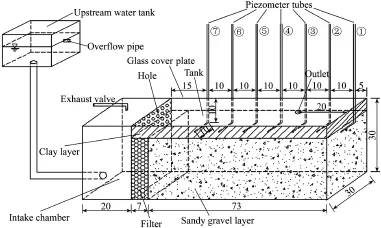
Fig.1.Schematicrepresentationofexperimentalapparatus(units:cm).
Fig.1 shows the schematic representation of the experimental apparatus.The tank was made of transparent organic glass.The width,depth,and length of the tank were 30,30, and 100 cm,respectively.An intake chamber with a length of 20 cm was built on the left side of the tank.Holes with similar diameters were arranged on the right wall of the intake chamber and a filter consisting of gravel was placed upstream of the soil sample.This filter was used to create a more uniform water pressure distribution on the upstream side of the soil sample.Seven piezometer tubes embedded at different locations in the soil sample were used to measure water level fluctuations.A pre-set outlet with a diameter of 5 cm was set on the right side of the glass cover-plate.It penetrated the clay layer,with one side fixed on the glass cover-plate,and the other side fixed on the surface of the sandy gravel soil sample.The outlet was connected to the downstream water tank by a plastic tube through which water and the eroded particles flowed and were collected.This experimental device allowed the measurement of the erosion rate,hydraulic parameters(water level,hydraulic gradient, and discharge),and geotechnical parameters(grain size distribution and porosity of the sandy gravel,and thickness of the overlying clay).
2.2.Experimental materials
The soil sample was a mixture of gravel with a diameter of 2-10 mm and sand with a diameter of less than 1 mm.The soil sample was gap-graded sandy gravel that could be considered internally unstable and was similar to“Sample A”in Skempton and Brogan(1994).The grain size distribution of the soil sample is shown in Fig.2(obtained using a sieve analysis).Soil sample properties and experimental conditions for three experiments are tabulated in Table 1.
2.3.Experimental procedure
The major stages of the experiments were as follows:
(1)Preparing the soil sample:First,moderate masses of dry sandy gravel and water were prepared and mixed completely. Then,the mixed soil sample was divided into several portions to be compacted in layers in the tank.Each layer,with a thickness of approximately 5 cm,was compacted to a predetermined density.At the same time,gravel was placed onthe upstream side of the soil sample and used as a filter. Subsequently,the top of the soil sample was covered with a clay layer,and then a glass cover plate was placed as a lid on the clay.Finally,the soil sample was saturated at a low level of hydraulic head difference by raising the elevation of the upstream water tank for more than 24 h.

Fig.2.Grain size distribution of soil sample.
(2)Applying seepage pressure and measuring erosion:The seepage pressure was applied by gradually raising the elevation of the upstream water tank.Each step lasted a sufficiently long duration(about 20 min)to obtain a stable flow rate in the model,at which the piezometric level did not fluctuate further and the particles were no longer eroded.The pressurized water flowed into the specimen from the inlet and discharged from the outlet.At the end of each step,the eroded particles were collected and dried in an oven.
(3)Recording experimental data:Water levels at different locations were captured with piezometer tubes.The relationship between the hydraulic gradient and the flow velocity was recorded,along with the mass of eroded fine particles through the outlet.
3.Experimental results and analysis
3.1.Progressionofpipingunderdifferentclaythicknesses
3.1.1.Experiment 1:Clay layer with a thickness of 2 cm and sandy gravel layer with a thickness of 28 cm
The upstream water level H was gradually increased from 8.5 to 136.5 cm(the elevation of the tank top surface was considered 0 cm).Table 2 presents the detailed experimental data,where i is the average hydraulic gradient,defined as thedifference between the upstream water level and the height of the outlet divided by the distance from the upstream side of the tank to the outlet;v is the average velocity of the water seeping through the cross-section,defined as the outlet discharge divided by the cross-sectional area of the permeable layer;M is the mass of the eroded fine particles;and N is the serial number of erosion occurrence.

Table 1Soil sample properties and experimental conditions.
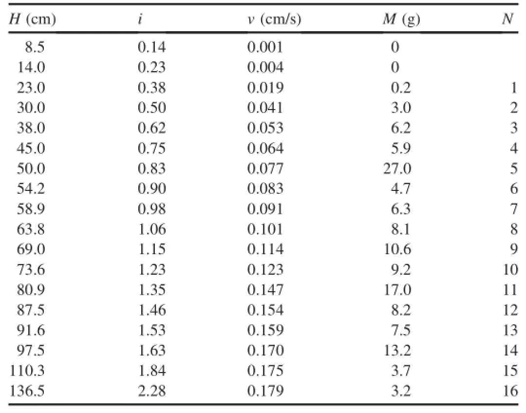
Table 2Detailed data from experiment 1.
The following results can be obtained from experiment 1:
(1)At i ranging from 0.14 to 0.23,no particles were washed out of the sandy gravel layer.
(2)At i=0.38,a few fine particles began to migrate,and the average velocity of the water seeping through the crosssection increased significantly,so the critical hydraulic gradient icrwas considered to be 0.38.
(3)At i=0.83,the eroded mass increased significantly to 27.0 g.Furthermore,the clay around the outlet cracked.
(4)At i ranging from 0.9 to 1.63,the measured eroded mass stayed at about the same order of magnitude,but the data were variable with no obvious trend.The crack gradually advanced upstream along with the progression of particle erosion,until it finally reached the edge of the filter.
(5)At i=1.84 and i=2.28,the measured eroded mass decreased to 3.7 g and 3.2 g,respectively.
Fig.3 shows the destruction of the sandy gravel layer and the overlying clay layer after experiment 1.After removal of the glass cover plate and the clay layer,it can be observed from Fig.3(a)that most of fine particles on the interface between the clay layer and the sandy gravel layer were washed out and a tunnel was clearly formed.A tunnel with a very shallow depth stretched from the outlet to the intake chamber and narrowed at the outlet.Beyond this,the fine particles were barely eroded,maintaining the original state.Fig.3(b)depicts the progression of cracks in the overlying clay layer.The location of the cracks corresponds to that of the piping tunnel. The experimental results show that the progression of the cracks is closely related to the erosion of fine particles in the sandy gravel layer.After fine particles in the sandy gravellayer are eroded,a local concentrated piping tunnel forms, which causes the overlying clay to lose support and gradually subside,and eventually results in cracks in the clay.Therefore, the formation and progression of cracks always follow the erosion of particles in the sandy gravel layer.
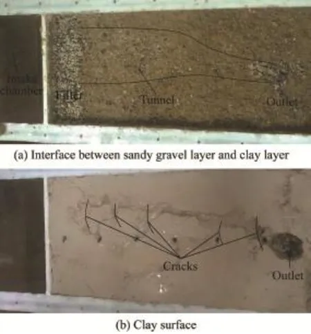
Fig.3.Destructionofsandygravellayerandclaylayerinexperiment1.
3.1.2.Experiment 2:Clay layer with a thickness of 5 cm and sandy gravel layer with a thickness of 25 cm
The upstream water level was gradually increased from 13 to 119.6 cm.Table 3 presents detailed data from experiment 2.
The following results were obtained from experiment 2:
(1)At i ranging from 0.22 to 0.39,no particles were washed out of the sandy gravel layer.
(2)At i=0.57,a few fine particles began to migrate,and the average velocity of the water seeping through the crosssection increased significantly,so the critical hydraulic gradient icrwas 0.57.
(3)At i=0.91,1.05,and 1.11,the number of erosion occurrences increased to ten,five,and two,respectively.This behavior in which multiple erosions occurred at the constant upstream water level was regarded as intermittent erosion.The eroded mass was non-uniform,and the average velocity at the constant water level fluctuated.Moreover,the clay layer began to crack at i=0.91.
(4)At i ranging from 1.25 to 1.99,the eroded mass fluctuated sharply,and the crack extended to the edge of the filter at i=1.46.
At the upstream water level of 54.8 cm,the erosion of fine particles was monitored and recorded ten times.The eroded mass was non-uniform and fluctuated significantly.It was observed that the water flow was unstable during the erosion process(sometimes clean and sometimes turbid).Turbid flow was accompanied by a decrease of the piezometric level,but then the piezometric level rose again in a minute.Furthermore, the average velocity of the water seeping through the crosssection fluctuated.Forexample,the average velocity increased from 0.097 to 0.115 cm/s first,then decreased to0.112 cm/s,and finally increased to 0.125 cm/s.By analyzing these observations,it can be concluded that the progression of piping is a complicated and iterative process involving fine particles erosion,clogging of pores,and flushing of the clogged pores.When the hydraulic pressure exceeds the strength of the clogging layer,the clogging layer is shattered,and the hydraulic pressure of the clogging layer is released instantaneously.This causes turbid flow and an instantaneous decrease in the piezometric level.Similar behavior was observed when the upstream water level was raised to 63 cm.

Table 3Detailed data from experiment 2.
Fig.4 shows the erosion of the sandy gravel and the clay after experiment 2.After removing the glass cover plate and the clay layer,it can be observed from Fig.4(a)that the fine particles on the interface between the clay layer and the sandy gravel layer were eroded by seepage,and only the large skeleton particles were left uneroded,indicating that a concentrated tunnel formed.The scope of erosion was larger than that in experiment 1.Fig.4(b)depicts the progression of cracks in the clay layer and the visible erosion of clay.It is evident that the water flowing out of the cracks greatly eroded the overlying clay.
3.1.3.Experiment 3:Clay layer with a thickness of 9 cm and sandy gravel layer with a thickness of 21 cm
The upstream water level gradually increased from 8.5 to 82.8 cm.Table 4 presents detailed data from experiment 3, where*is annotated below Table 3.
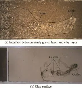
Fig.4.Destructionofsandygravellayerandclaylayerinexperiment2.
The following results were obtained from experiment 3:
(1)At i ranging from 0.14 to 0.98,no particles were eroded.
(2)At i=1.17,fine particles began to be eroded,and the average velocity of the water seeping through the cross-section increased greatly,so the critical hydraulic gradient icrwas considered to be 1.17.Furthermore,at this hydraulic gradient, erosion occurred three times,and the eroded mass was relatively small.
(3)At i=1.24,the eroded mass suddenly increased to 31.0 g.This was associated with rapid erosion of fine particles and cracking of the clay layer.
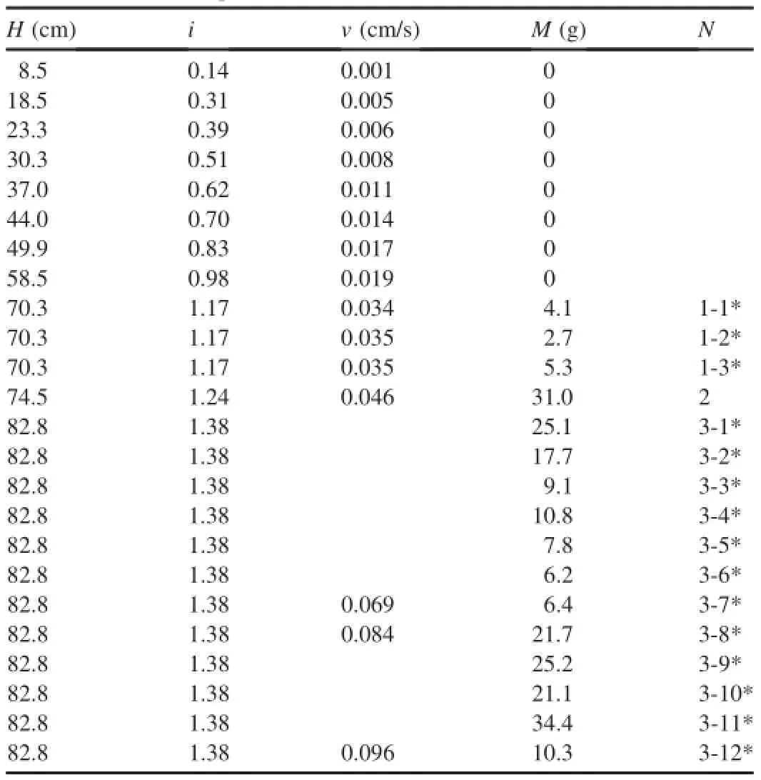
Table 4Detailed data from experiment 3.
(4)At i=1.38,the number of erosion occurrences was twelve,and most of the eroded mass was large.The significant fluctuations in the average velocity and piezometric level were also observed in this stage.Cracks gradually developed upstream and finally reached the edge of the filter during the later period of this hydraulic gradient.
It is observed from Fig.5(a)that the area of the piping tunnel is very large.The shape of the cracks on the clay approximates the water level contour,as shown in Fig.5(b).
Comparing the above three experiments,it is concluded that the thickness of the overlying clay has a considerable influence on the progression of piping,as follows:
(1)The thickness of the overlying clay has a considerable influence on the progression of erosion.When the clay is thicker,the critical hydraulic gradient will be larger.Once piping is initiated,the formation of a piping tunnel progresses quickly.The critical hydraulic gradient icrwas 0.38 in experiment 1,0.57 in experiment 2,and 1.17 in experiment 3. However,the piping tunnel finally reached the edge of the filter at i=1.63 in experiment 1,i=1.46 in experiment 2,and i=1.38 in experiment 3.
(2)The thickness of the overlying clay has an influence on the flat area of the piping tunnel.The area of the piping tunnel increases with the thickening of the clay layer.This may occur because the thinner clay deforms and settles easier,which restrains the progression of erosion of fine particles and the development of the piping tunnel.
(3)The thickness of the overlying clay also considerably influences the shape of the cracks forming in the clay.The erosion of fine particles is related to the hydraulic gradient, which depends on the water levels in the tank,so the shape of the upstream end of the piping tunnel is the same as the shape of the water head contours.On the other hand,the cracks in the clay are closely related to the geometry of the tunnel, which eventually results in the shape of the cracks approximating the water head contours.When the overlying clay isthicker,the area of the piping tunnel will be larger,resulting in more visible cracks.
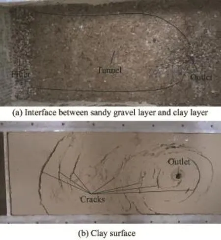
Fig.5.Destructionofsandygravellayerandclaylayerinexperiment3.
3.2.Relationship between clay thickness and erosion rate
Fig.6 depicts the relationship between the cumulative eroded mass and upstream water level in the aforementioned three experiments.It can be seen that the cumulative eroded mass increases nonlinearly with the upstream water level, indicating that the eroded mass is non-uniform.When this observationisconsideredalongwiththemultipleerosionsatthe constant water level,it is inferred that the progression of piping is a complicated and iterative process,involving the erosion of fine particles,clogging of pores,and flushing of clogged pores. The fine particles on the upstream end of the piping tunnel are gradually eroded by seepage pressure.However,most of the coarse particles cannotcollapseandbetransported.Someofthe coarse particles are deposited and may form a filter to prevent the washing out of the fine particles from the underlying sandy gravel layer.When this filter forms,a clogging layer is formed as well,leading to a sharp decrease of the eroded mass.Over time,the clogging layer is pushed out,resulting in a significant increase of the eroded mass.This expands the tunnel,but flow and erosion are likely to decrease again due to the clogging,so that repeated cycles of clogging,flushing of the clogging layer, and an increase in erosion can occur.
It can be seen from Fig.6 that the thickness of the clay significantly influences the erosion rate.Erosion of the sandy gravel covered by a thicker clay layer begins later than that of sandy gravel covered by a thinner clay layer,but the erosion rate is very high once erosion of the sandy gravel below the thicker clay is initiated.This behavior can be attributed to the deformability of the clay layer.The thinner clay deforms and settles more easily,which constricts the piping tunnel and restrains the erosion of the sandy gravel.
3.3.Effects of clay thickness on average velocity through cross-section
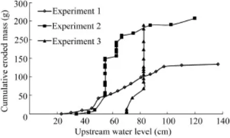
Fig.6.Relationship between cumulative eroded mass and upstream water level.
Since the thicknesses of the overlying clay in these three experiments were different,the outlet discharge was influenced by the cross-sectional area of the permeable layer and the deformation of the overlying clay.In order to study the deformation of the overlying clay,the average velocity of water seeping through the cross-section was considered the analysis subject.Fig.7 shows the relationship between the upstream water level and the average velocity of the water seeping through the cross-section.It is noted that the average velocity of water seeping through the cross-section at a constant upstream water level was fluctuant,as shown in Tables 3 and 4,so the average velocity value corresponding to an upstream water level in Fig.7 was the average of several fluctuant values.It can be seen that the average velocity increases linearly with the upstream water level during the initial stages of the experiment,i.e.,its behavior obeys Darcy's law.With the erosion of fine particles,the velocity increases nonlinearly with the upstream water level.
Furthermore,the average velocity of the water seeping through the cross-section is closely related to the eroded mass. The larger the eroded mass is,the more quickly the permeability increases,as does the average velocity.Before the erosion of fine particles,the average velocities of the water seeping through the cross-section in the three experiments were approximately equal(as shown in Fig.7).With an increase in the upstream water level,soil in experiment 1 was eroded first,and the average velocity increased significantly, so the average velocity in experiment 1 was larger than those in the other two experiments at this stage.However,the erosion rate in experiment 2 was very high,which resulted in a speedy increase in the average velocity,and finally the average velocity exceeded that in experiment 1.The variation of the average velocity in experiment 3 had similar characteristics because of the high erosion rate.The erosion of fine particles in experiment 3 was difficult to initiate,so the average velocity increased much more slowly with the upstream water level before the erosion.However,the average velocity in the later period of erosion increased so quickly that it had a tendency to exceed the average velocities in experiments 1 and 2 as a result of a high erosion rate.
In conclusion,the thickness of the overlying clay significantly influences the progression of piping.As the overlying clay layer is thinner,the particle motion occurs earlier.However,with the development of a piping tunnel,the overlying clay deforms and settles,which constricts the piping tunnel and restrains the erosion of fine particles,therefore restricting the increase in velocity.When the overlying clay is thicker,the initiation of fine particle motion is slower,but once theparticles start to be eroded,the erosion rate and progression of piping is rapid due to the low deformability of the overlying clay,resulting in a rapid increase of average water velocity.
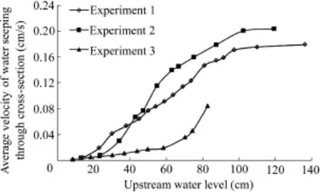
Fig.7.Relationshipbetweenaveragevelocityandupstreamwaterlevel.
4.Conclusions
A series of experiments on piping in an internally unstable sandy gravel foundation was carried out using a customdesigned apparatus.These experiments allowed an accurate assessment of the influence of the thickness of an overlying clay layer on the initiation and progression of piping.The major findings of this study are as follows:
(1)The thickness of the overlying clay layer considerably influences the initiation and progression of piping.With a thicker overlying clay,the critical hydraulic gradient required to initiate piping is larger,the piping tunnel progresses more rapidly,and an increase in the average velocity is larger due to the low deformability of the thick clay.
(2)The flat area of the piping tunnel and the shapes of the cracks in the clay resulting from the erosion are also influenced by the thickness of the overlying clay.When the overlying clay is thicker,the erosion rate increases rapidly due to less deformation of the overlying clay and less constriction of the piping tunnel.In this case,there is severe erosion of the sandy gravel,and the resulting flat area of the piping tunnel is larger,with more visible cracks whose shapes approximate the water head contours.
(3)The progression of piping is a complicated and iterative process involving erosion of fine particles,clogging of pores, and subsequent flushing of the clogged pores.Two types of erosion are identified in the progression of piping:one causes the tunnel to advance upstream,and the other increases the tunnel depth.The erosion rate is typically non-uniform and intermittent at a constant water level.
References
Al-Riffai,M.,Nistor,I.,2010.Impact and analysis of geotechnical processes on earthfill dam breaching.Nat.Hazards 55(1),15-27.http://dx.doi.org/ 10.1007/s11069-010-9586-6.
Bendahmane,F.,Marot,D.,Alexis,A.,2008.Experimental parametric study of suffusion and backward erosion.J.Geotech.Geoenviron.Eng.134(1), 57-67.http://dx.doi.org/10.1061/(ASCE)1090-0241(2008)134:1(57).
Boucher,S.G.,1990.Field Tunnel Erosion,Its Characteristics and Amelioration.Monash University,Clayton.
Chang,D.S.,Zhang,L.M.,2013.Critical hydraulic gradients of internal erosion under complex stress states.J.Geotech.Geoenviron.Eng.139(9), 1454-1467.http://dx.doi.org/10.1061/(ASCE)GT.1943-5606.0000871.
Fannin,R.J.,Moffat,R.,2006.Observations on internal stability of cohensionless soils.Geotechnique 56(7),497-500.http://dx.doi.org/10.1680/ geot.2006.56.7.497.
Fell,R.,Wan,C.F.,Cyganiewicz,J.,Foster,M.,2003.Time for development of internal erosion and piping in embankment dams.J.Geotech.Geoenviron.Eng.129(4),307-314.http://dx.doi.org/10.1061/(ASCE)1090-0241(2003)129:4(307).
Foster,M.,Fell,R.,Spannagle,M.,2000a.The statistics of embankment dam failures and accidents.Can.Geotech.J.37(5),1000-1024.http:// dx.doi.org/10.1139/cgj-37-5-1000.
Foster,M.,Fell,R.,Spannagle,M.,2000b.A method for assessing the relative likelihood of failure of embankment dams by piping.Can.Geotech.J. 37(5),1025-1061.http://dx.doi.org/10.1139/cgj-37-5-1025.
Indraratna,B.,Nguyen,V.T.,Rujikiatkamjorn,C.,2011.Assessing the potential of internal erosion and suffusion of granular soils.J.Geotech. Geoenviron.Eng.137(5),550-554.http://dx.doi.org/10.1061/(ASCE) GT.1943-5606.0000447.
Li,M.X.,2008.Seepage Induced Instability in Widely Graded Soils.Ph.D. Dissertation.University of British Colombia,Vancouver.
Luo,Y.L.,Qiao,L.,Liu,X.X.,Zhan,M.L.,Sheng,J.C.,2013.Hydro-mechanical experimentsonsuffusionunderlong-termlargehydraulicheads.Nat.Hazards 65(3),1361-1377.http://dx.doi.org/10.1007/s11069-012-0415-y.
Maknoon,M.,Mahdi,T.F.,2010.Experimental investigation into embankment external suffusion.Nat.Hazards 54(3),749-763.http://dx.doi.org/ 10.1007/s11069-010-9501-1.
Marot,D.,Bendahmane,F.,Rosquoet,F.,Alexis,A.,2009.Internal flow effects on isotropic confined sand-clay mixtures.Soil Sediment Contam. 18(3),294-306.http://dx.doi.org/10.1080/15320380902799524.
Marot,D.,Sail,Y.,Alexis,A.,2010.Experimental bench for study of internal erosion in cohesionless soils.In:Burns,S.E.,Bhatia,S.K., Avila,C.M.C.,Hunt,B.E.,eds.,Proceedings of the 5th International Conference on Scour and Erosion(ICSE-5).ASCE,San Francisco, pp.418-427.
Marot,D.,Le,V.D.,Garnier,J.,Thorel,L.,Audrain,P.,2012.Study of scale effect in an internal erosion mechanism:Centrifuge model and energy analysis.Eur.J.Environ.Civ.Eng.16(1),1-19.http://dx.doi.org/10.1080/ 19648189.2012.667203.
Moffat,R.,Fannin,R.J.,2011.A hydromechanical relation governing internal stability of cohesionless soil.Can.Geotech.J.48(3),413-424.http:// dx.doi.org/10.1139/T10-070.
Moffat,R.,Fannin,R.J.,Garner,S.J.,2011.Spatial and temporal progression of internal erosion in cohesionless soil.Can.Geotech.J.48(3),399-412. http://dx.doi.org/10.1139/T10-071.
Richards,K.S.,Reddy,K.R.,2008.Experimental investigation of piping potential in earthen structures.Geosustainability and geohazard mitigation. Proc.GeoCongress 178,367-376.http://dx.doi.org/10.1061/40971(310)46.
Richards,K.S.,Reddy,K.R.,2010.True triaxial piping test apparatus for evaluation of piping potential in earth structures.Geotechn.Test.J.33(1), 83-95.http://dx.doi.org/10.1520/GTJ102246.
Sail,Y.,Marot,D.,Sibille,L.,Alexis,A.,2011.Suffusion tests on cohesionless granular matter:Experimental study.Eur.J.Environ.Civ.Eng. 15(5),799-817.http://dx.doi.org/10.1080/19648189.2011.9693366.
Skempton,A.W.,Brogan,J.M.,1994.Experiments on piping in sandy gravels. Geotechnique44(3),449-460.http://dx.doi.org/10.1680/geot.1994.44.3.449.
Wan,C.F.,Fell,R.,2008.Assessing the potential of internal instability and suffusion in embankment dams and their foundations.J.Geotech.Geoenviron.Eng.134(3),401-407.http://dx.doi.org/10.1061/(ASCE)1090-0241(2008)134:3(401).
Zhang,J.,Guo,Z.X.,Cao,S.Y.,Yang,F.G.,2012.Experimental study on scour and erosion of blocked dam.Water Sci.Eng.5(2),219-229.http:// dx.doi.org/10.3882/j.issn.1674-2370.2012.02.010.
This work was supported by the 973 Program of China(Grant No. 2012CB417005)and the Postgraduate Research and Innovation Plan Project in Jiangsu Province(Grant No.CXZZ13_0243).
*Corresponding author.
E-mail address:wshwy.871112@163.com(Shuang Wang).
Peer review under responsibility of Hohai University.
http://dx.doi.org/10.1016/j.wse.2016.06.001
1674-2370/© 2016 Hohai University.Production and hosting by Elsevier B.V.This is an open access article under the CC BY-NC-ND license(http:// creativecommons.org/licenses/by-nc-nd/4.0/).
 Water Science and Engineering2016年2期
- Water Science and Engineering的其它文章
- Evaluation of latest TMPA and CMORPH satellite precipitation products over Yellow River Basin
- A distributed Grid-Xinanjiang model with integration of subgrid variability of soil storage capacity
- 3D CFD validation of invert trap efficiency for sewer solid management using VOF model
- Layout effects and optimization of runoff storage and filtration facilities based on SWMM simulation in a demonstration area
- Spatiotemporal patterns of non-point source nitrogen loss in an agricultural catchment
- Effects of heterogeneity distribution on hillslope stability during rainfalls
