
无共模电压SVPWM多桥臂逆变器的拓扑结构演化与电机性能研究
2016-06-29 09:44:32孙斐然沈建新
电工技术学报 2016年11期
孙斐然 沈建新
(浙江大学电气工程学院 杭州 310027)
无共模电压SVPWM多桥臂逆变器的拓扑结构演化与电机性能研究
孙斐然沈建新
(浙江大学电气工程学院杭州310027)
摘要三相开放式绕组永磁同步电动机(PMSM)可采用单电源双逆变器供电,与传统单逆变器供电的PMSM相比具有可选电压矢量多及控制方法灵活等优点,有利于改善电机驱动性能,但逆变器桥臂数量较多,硬件结构复杂。为此,针对无共模电压空间矢量脉宽调制(SVPWM)控制方法,对单电源双逆变器(即六桥臂)驱动拓扑结构进行演化,逐步减少桥臂数量,并对比分析各演化结构驱动下的电机性能。各演化结构虽然引入了额外的零序电流通路,但在无共模电压SVPWM控制下没有零序电压激励,因此并无零序电流产生,故拓扑结构的演化并不影响电机控制性能。该拓扑结构演化不仅为逆变器与电机绕组的选型设计提供参考,还揭示了无共模电压SVPWM的本质特性。
关键词:多桥臂逆变器空间矢量脉宽调制无共模电压拓扑结构演化
0引言
与传统两电平逆变器相比,三电平逆变器具有开关损耗更小及输出波形的谐波频谱更好等优点,但其结构及PWM控制算法也要复杂得多,且存在中点电位波动问题[1-9]。双逆变器结构的输出电压矢量与三电平逆变器相当[10,11],并且无中性点波动问题,因此逐渐成为研究热点。
双逆变器的PWM方法各有优劣,但算法相对三电平逆变器都较为简单[10-23]。文献[13,14]介绍了一种新的切换模式,使得双逆变器的开关次数大大降低。文献[15]提出的随机SVPWM能有效减少开关频率的谐波成分。采用解耦SVPWM技术时,相电流的纹波含量会随电机调制指数的增加而减小[16]。文献[17-23]通过不同方法抑制零序电流,从而舍去隔离电源,只由单电源供电,则双逆变器结构就可看成是六桥臂逆变器。其中,文献[17,18]提出添加辅助开关,通过切换中性点来抑制零序电流。而在文献[19,20]中,只采用不产生共模电压的矢量组进行PWM。
本文以三相开放式绕组永磁同步电动机(Permanent Magnet Synchronous Motor,PMSM)作为研究对象,根据无共模电压SVPWM方法[20]对单电源双三相(即六桥臂)逆变器驱动系统进行结构演化和性能分析,不仅简化了驱动器拓扑,也揭示了无共模电压SVPWM方法的本质。
1独立电源供电双逆变器结构
图1为双三相逆变器及开放式绕组永磁同步电动机驱动系统的拓扑结构。两个逆变器(INV1和INV2)由独立电源供电,交流侧分别与开放式PMSM三相定子绕组两端(a1、b1、c1和a2、b2、c2)相连。
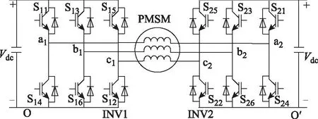
图1 三相开放式绕组PMSM的双电源双逆变器驱动结构Fig.1 Topology of dual power supplies and dual inverters for PMSM drive
如图2a所示,逆变器INV1产生的空间电压矢量为1、2、…、8,INV2产生的空间电压矢量则为1′、2′、…、8′,每个电压矢量对应的各桥臂的开关状态用括号中的三位二进制数表示。若上桥臂导通、下桥臂关断,则用“1”表示,反之为“0”。两个逆变器的空间电压矢量合成可得到双逆变器的电压矢量,如图2b所示,其编号如14′(表示由INV1的电压矢量V1和INV2的电压矢量V4′合成,即V14′=V1-V4′,其余类推)等,共有54种非零电压矢量合成方式和10种零电压矢量合成方式。而这54种非零电压矢量存在冗余,在空间上其实只有18个,可用图2b中的OA、OB、OC、OD、OE、OF、OG、OH、OI、OJ、OK、OL、OM、ON、OP、OQ、OR、OS表示。

图2 双逆变器的空间电压矢量合成原理Fig.2 Principle of synthesis of space voltage vectors with dual inverters
2单电源双逆变器结构与无共模电压SVPWM
非零矢量24′、15′、35′、26′、46′、31′、51′、42′、62′、53′、13′、64′和零矢量11′、22′、33′、44′、55′、66′、77′、88′不产生共模电压[19,20]。若只使用这些矢量进行PWM调制,则零序电流不会在绕组中流通,因此,双逆变器不再需要通过独立电源隔离零序电流。由单电源供电的双逆变器(实际为六桥臂逆变器)结构如图3所示。

图3 三相开放式绕组PMSM的单电源双逆变器(六桥臂)驱动结构Fig.3 Topology of single power supply and dual inverters(six-leg)for PMSM drive
脉宽调制过程中只使用无共模电压矢量,即可实现无共模电压SVPWM。由图2b可知,无共模电压的空间矢量构成了六边形HJLNQS。其中,矢量OH、OJ、OL、ON、OQ、OS可由15′、26′、31′、42′、53′、64′或24′、35′、46′、51′、62′、13′实现[20]。零矢量选择77′、88′。
以所需电压矢量落在ΔOSH中为例简要介绍上述PWM的基本原理:
1)当非零矢量采用15′、26′、31′、42′、53′、64′时,所需电压矢量由15′、64′、77′和88′合成。逆变器INV1按照7-1-6-8-6-1-7矢量顺序进行切换,逆变器INV2则按7′-5′-4′-8′-4′-5′-7′矢量顺序切换。两个逆变器的开关时序有所不同。
2)当非零矢量采用24′、35′、46′、51′、62′、13′时,所需电压矢量由13′、24′、77′和88′合成。逆变器INV1 按照7-1-2-8-2-1-7矢量顺序进行切换,逆变器INV2则按7′-3′-4′-8′-4′-3′-7′矢量顺序切换。
上述两种PWM虽然选择了不同的矢量组,但在原理上并无差异。本文主要以矢量15′、26′、31′、42′、53′、64′、77′和88′为例进行PWM控制。
3结构拓扑演化
用绕组端号区分与之相连的逆变器桥臂,则逆变器INV1和INV2的开关状态可表示为(ma1mb1mc1)和(ma2mb2mc2)。表1描述了逆变器桥臂在无共模电压SVPWM过程中的开关状态。
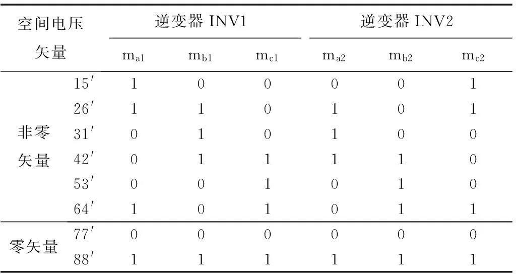
表1 逆变器桥臂开关管状态
从表1可发现,b1和a2桥臂上的开关管动作总是相同的。因此,将b1和a2共用一个桥臂,如图4所示。所以,从电机供电的角度看,在采用表1列出的无共模电压空间矢量时,图4所示的五桥臂拓扑结构与图3所示的六桥臂逆变器结构相同。但从电路角度看,图4所示的结构引入了一条绕组端点b1和a2之间的通路,由此可能会改变电机中的电流波形及转矩性能,因此需要作性能分析与对比研究。

图4 五桥臂逆变器驱动结构Fig.4 Topology of five-leg inverter drive
由表1还可发现,任意矢量对应的开关状态mc1与mb2也总是相同的,故电机与逆变器可进一步演化为四桥臂结构,如图5所示,即将绕组端c1和b2共用同一桥臂。当然,还可进一步演化,得到图6所示的三桥臂逆变器拓扑结构,即将绕组端a1与c2也共用同一桥臂。三桥臂逆变器结构等同于b1端与a2端、c1端与b2端、a1端与c2端两两相连,因此将电机的开放式绕组演化为传统的三角形联结绕组,如图7所示。

图5 四桥臂逆变器驱动结构Fig.5 Topology of four-leg inverter drive
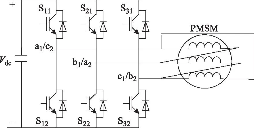
图6 三桥臂逆变器驱动结构Fig.6 Topology of three-leg inverter drive
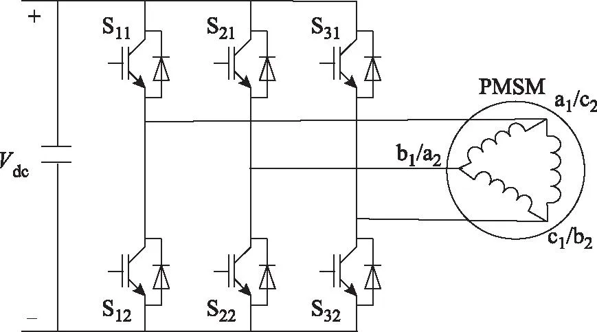
图7 传统三角形绕组电机及逆变器驱动结构Fig.7 Traditional Δ-connection winding motor and inverter
从双逆变器(六桥臂)演化到三桥臂逆变器的过程,同时也是定子绕组由开放式逐渐变为三角形联结的过程。在此过程中,虽然始终采用无共模电压矢量,但电机绕组的拓扑结构已发生变化,提供了额外的零序电流通路,因此,电机性能的变化值得分析研究。
4性能分析与对比研究

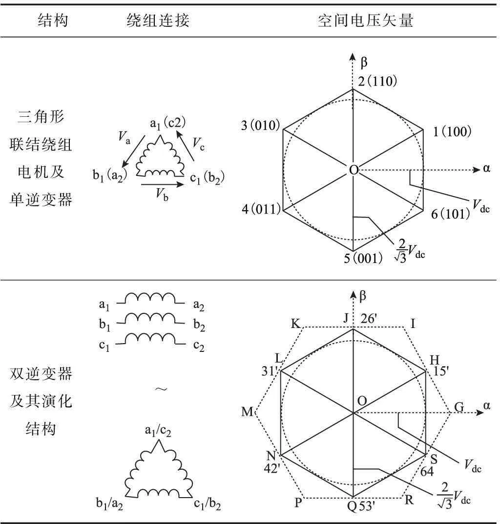
表2 拓扑演化及空间电压矢量

在Matlab/Simulink仿真研究中,开放式绕组电机选用4极三相PMSM,定子电阻为0.028 8 Ω,转子永磁体产生正弦磁场,在电枢绕组中产生的磁链幅值为0.029 6 Wb,d轴与q轴电感均为0.124 mH,负载转矩为2 N·m,额定转速为1 000 r/min。
图8为六桥臂逆变器驱动开放式绕组PMSM的稳态性能。其中,图8a是相电压波形;图8b是相电流波形,基本为正弦形,但含有少量谐波分量,尤其是7次和11次,如图8d所示(图中纵坐标表示各次谐波电流的幅值相较基波的百分比),THD为3.54%;电磁转矩也基本稳定,转矩脉动峰值约为0.1 N·m,即5%。
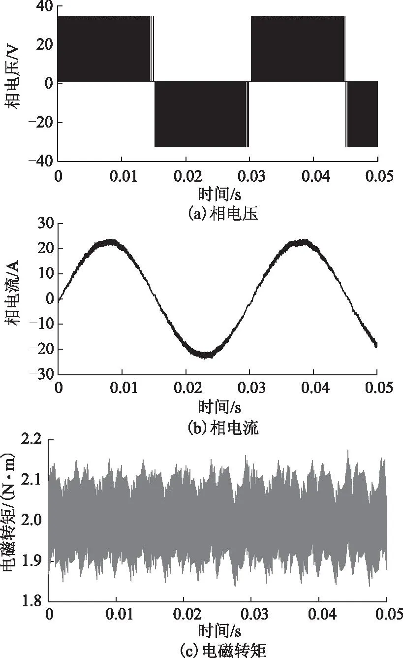

图8 六桥臂逆变器驱动系统的性能Fig.8 Performance of six-leg inverter drive system
在演化所得的五桥臂、四桥臂和三桥臂驱动系统中,相电压波形与六桥臂逆变器驱动系统一致。其所对应的相电流和电磁转矩波形如图9~图11所示。可见电流波形都基本正弦,基波分量相当,7次和11次谐波分量略微明显,见图12a~图12c,电流THD仍在3.5%左右。值得注意的是,各演化拓扑结构的驱动系统并未带来额外的零序电流(如3次、6次、9次等谐波)。这是因为,虽然从图3所示的单电源六桥臂开绕组系统逐步减少桥臂数量直至演化为图6所示的三桥臂拓扑,从电路角度看是增加了零序电流的通路,但逆变器始终采用无共模电压矢量,即没有给电机施加零序的电压激励,因此对于理想的正弦型PMSM而言,不会产生零序的电流响应。由此也可知,各演化拓扑结构的电磁转矩波形也基本相同。所以,拓扑结构的演化并未对系统性能产生不良影响。

图9 五桥臂逆变器驱动系统的性能Fig.9 Performance of five-leg inverter drive system

图10 四桥臂逆变器驱动系统的性能Fig.10 Performance of four-leg inverter drive system
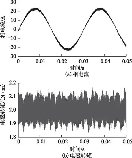
图11 三桥臂逆变器驱动系统的性能Fig.11 Performance of three-leg inverter drive system

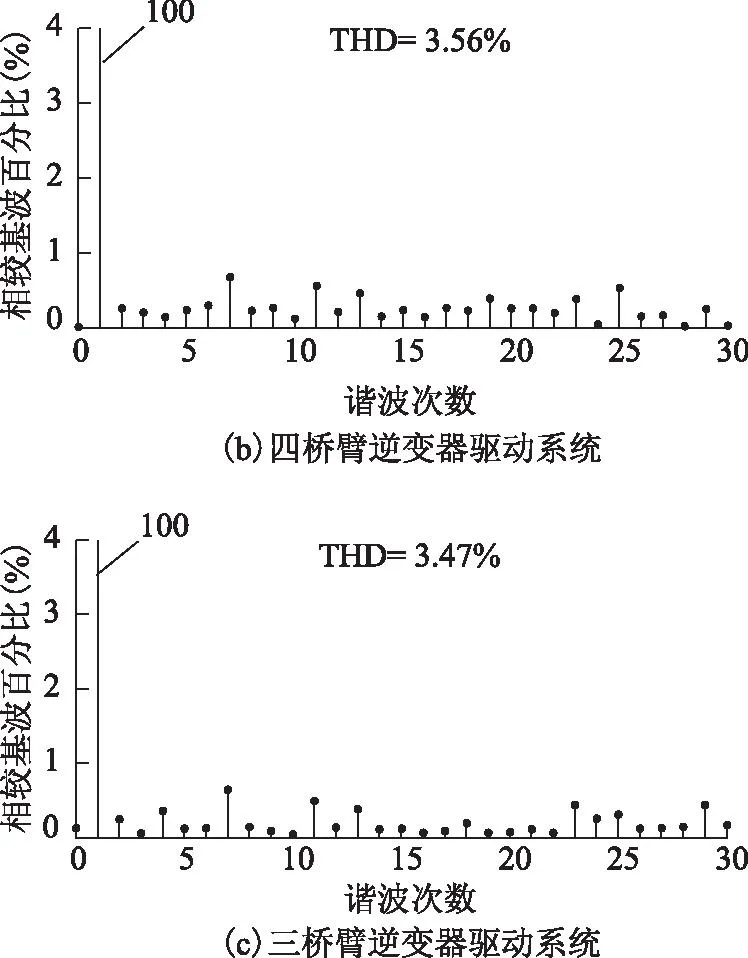
图12 不同驱动系统的相电流谐波分析Fig.12 Phase current spectra with various drive systems

5结论
针对无共模电压SVPWM,本文对开放式绕组PMSM的双逆变器(六桥臂)驱动结构进行演化,逐步得到五桥臂、四桥臂、三桥臂逆变器驱动系统。相比双逆变器驱动系统,演化结构的桥臂与功率管数量减少,电路简化;但功率管的标称电流须相应提高。虽然演化的驱动结构引入了额外的零序电流通路,但在无共模电压SVPWM控制下,并未引起额外的零序电流,这也是演化的驱动结构的优点之一。
无共模电压SVPWM方法可单电源供电,调制算法简单。本文根据结构演化过程揭示了该SVPWM实质上与单逆变器驱动三角形联结绕组的电机的SVPWM相当。本文对采用无共模电压SVPWM的驱动系统进行了梳理,可为逆变器与电机绕组的选型设计提供参考。
参考文献
[1]Seo J H,Choi C H,Hyun D S.A new simplified space-vector PWM method for three-level inverters[J].IEEE Transactions on Power Electronics,2001,16(4):545-550.
[2]王若醒,吴迎霞,杨恢宏,等.两级式T型三电平光伏逆变器的关键技术研究及实现[J].电力系统保护与控制,2015,43(4):58-62.
Wang Ruoxing,Wu Yingxia,Yang Huihong,et al.Research on key technologies of double-stage T-type three-level photovoltaic inverter[J].Power System Protection and Control,2015,43(4):58-62.
[3]王慧敏,温坤鹏,张云,等.基于精细分区控制的三电平逆变器中点电位平衡策略[J].电工技术学报,2015,30(19):144-152.
Wang Huimin,Wen Kunpeng,Zhang Yun,et al.Neutral point potential balance strategy for NPC three-level inverter based on meticulous partition control[J].Transactions of China Electrotechnical Society,2015,30(19):144-152.
[4]Gupta A K,Khambadkone A M.A simple space vector PWM scheme to operate a three-level NPC inverter at high modulation index including overmodulation region,with neutral point balancing[J].IEEE Transactions on Industry Applications,2007,43(3):751-760.
[5]范波,赵伟刚,刘刚,等.基于优化虚拟矢量的三电平逆变器中点电位平衡闭环控制[J].电工技术学报,2015,30(4):179-186.
Fan Bo,Zhao Weigang,Liu Gang,et al.Closed-loop control of neutral-point voltage balance based on the optimized virtual space vector for three-level inverter[J].Transactions of China Electrotechnical Society,2015,30(4):179-186.
[6]Shen Z,Zheng J,Mei J.Capacitor potential balancing of neutral-point clamped three-level inverter based on improved virtual space vector PWM[J].Electric Power Automation Equipment,2011,31(3):79-84.
[7]刘斌,黄凯伦,伍家驹,等.一种具有中点电位平衡可降低损耗的三电平空间矢量调制方法[J].电工技术学报,2015,30(4):196-202.
Liu Bin,Huang Kailun,Wu Jiaju,et al.A novel SVPWM method considering neutral-point potential balancing and reducing switching losses for three-level inverter[J].Transactions of China Electrotechnical Society,2015,30(4):196-202.
[8]张伦健,谭国俊,陈利萍.基于双调制波技术的三电平Z源逆变器中点电位平衡控制[J].电力系统保护与控制,2013,41(7):91-96.
Zhang Lunjian,Tan Guojun,Chen liping.Neutral-point potential balance control for three-level Z-source inverters based on double modulation wave technique[J].Power System Protection and Control,2013,41(7):91-96.
[9]王兆宇,艾芊.三电平逆变器空间矢量调制及中点电压控制[J].电力系统保护与控制,2011,39(20):131-136.
Wang Zhaoyu,Ai Qian.Space vector modulation for three-level inverter and neutral point potential control[J].Power System Protection and Control,2011,39(20):131-136.
[10]Stemmler H,Guggenbach P.Configurations of high power voltage source inverter drives[C]//Fifth European Conference on Power Electronics and Applications,Brighton,1993,5:7-14.
[11]Ahmed S M W,Sowilam G M A,Salim A B S M,et al.Practical implementation of a dual inverter operates open ends induction motor[C]//2009 4th International Design and Test Workshop,Riyadh,2009:1-6.
[12]Mohapatra K K,Mohan N.Open-end winding induction motor driven with indirect matrix converter for common-mode elimination[C]//Proceedings of the 2007 Summer Computer Simulation Conference,San Diego,CA,2007:106-111.
[13]Shivakumar E G,Gopakumar K,Sinha S K,et al.Space vector PWM control of dual inverter fed open-end winding induction motor drive[C]//Sixteenth Annual IEEE Applied Power Electronics Conference and Exposition,Anaheim,CA,2001,1:399-405.
[14]Srinivas S,Ramachandra S K.Theoretical and experimental analysis for current in a dual-inverter-fed open-end winding induction motor drive with reduced switching PWM[J].IEEE Transactions on Industrial Electronics,2013,60(10):4318-4328.
[15]George D S,Baiju M R.Space vector based random pulse width modulation scheme for a 3-level inverter in open-end winding induction motor configuration[C]//IEEE International Symposium on Industrial Electronics,Hangzhou,2012:742-747.
[16]Sekhar K R,Srinivas S.Discontinuous decoupled PWMs for reduced current ripple in a dual two-level inverter fed open-end winding induction motor drive[J].IEEE Transactions on Power Electronics,2013,28(5):2493-2502.
[17]Somasekhar V T,Gopakumar K,Pittet A,et al.A novel PWM inverter switching strategy for a dual two-level inverter fed open-end winding induction motor drive[C]//4th IEEE International Conference on Power Electronics and Drive Systems,2001,1:196-202.
[18]Somasekhar V T,Gopakumar K,Pittet A,et al.PWM inverter switching strategy for a dual two-level inverter fed open-end winding induction motor drive with a switched neutral[J].IEE Proceedings-Electric Power Applications,2002,149(2):152-160.
[19]Baiju M R,Mohapatra K K,Kanchan R S,et al.A dual two-level inverter scheme with common mode voltage elimination for an induction motor drive[J].IEEE Transactions on Power Electronics,2004,19(3):794-805.
[20]Somasekhar V T,Gopakumar K,Shivakumar E G,et al.A space vector modulation scheme for a dual two level inverter fed open-end winding induction motor drive for the elimination of zero sequence currents[J].EPE Journal:European Power Electronics and Drives,2002,12(2):1-19.
[21]Somasekhar V T,Srinivas S,Kumar K K.Effect of zero-vector placement in a dual-inverter fed open-end winding induction-motor drive with a decoupled space-vector PWM strategy[J].IEEE Transactions on Industrial Electronics,2008,55(6):2497-2505.
[22]Somasekhar V T,Srinivas S,Prakash R B,et al.Pulse width-modulated switching strategy for the dynamic balancing of zero-sequence current for a dual-inverter fed open-end winding induction motor drive[J].IET Electric Power Applications,2007,1(4):591-600.
[23]Somasekhar V T,Srinivas S,Kumar K K.Effect of zero-vector placement in a dual-inverter fed open-end winding induction motor drive with alternate sub-hexagonal center PWM switching scheme[J].IEEE Transactions on Power Electronics,2008,23(3):1584-1591.
Investigation of Topology Evolution of Common-Mode-Voltage-Free SVPWM Multi-Leg Inverter and Motor Drive Performance
Sun FeiranShen Jianxin
(College of Electrical EngineeringZhejiang UniversityHangzhou310027China)
AbstractCompared with a traditional single inverter-fed permanent magnet synchronous motor(PMSM),the 3-phase open-end winding PMSM driven by single DC supply and dual inverters is benefited from more applicable voltage vectors,more flexible control method,as well as better drive performance,but suffers from the larger number of inverter legs and more complicated hardware structure.Therefore,in this paper,the drive topology of single-supply dual-inverter,i.e.six-leg inverter,with common-mode-voltage-free(CMVF)space vector pulse width modulation(SVPWM)is evolved so as to eliminate some of the inverter legs,whilst the motor performance with each evolved topology is comparatively analyzed.It is seen that the evolved topologies induce extra paths for the zero-sequence current which,however,is not actually generated due to the absence of the zero-sequence voltage under the CMVF SVPWM control.Thus,the motor performance is hardly deteriorated by the topology evolution.The proposed topology evolution not only provides a reference for the selection and design of the inverter and motor windings,but also reveals the innate character of the CMVF SVPWM.
Keywords:Multi-leg inverter,space vector pulse width modulation,common-mode-voltage-free,topology evolution
收稿日期2015-04-01改稿日期2015-05-26
作者简介E-mail:sunfr2405@163.com E-mail:J_X_Shen@zju.edu.cn(通信作者)
中图分类号:TM351
国家自然科学基金资助项目(51577165,51377140)。
孙斐然女,1990年生,硕士研究生,研究方向为永磁同步电机及其控制。
沈建新男,1969年生,教授,博士生导师,研究方向为电机拓扑与驱动控制、新能源技术等。
猜你喜欢
电工技术学报(2023年16期)2023-08-30 02:44:26
中国实用神经疾病杂志(2018年9期)2018-05-25 01:01:08
设备管理与维修(2016年7期)2016-04-23 06:51:36
电测与仪表(2016年22期)2016-04-12 00:19:58
通信电源技术(2016年5期)2016-03-22 01:10:13
电气传动(2015年4期)2015-07-11 06:10:56
电子工业专用设备(2015年4期)2015-05-26 09:10:33
电测与仪表(2015年2期)2015-04-09 11:28:58
中国医药导报(2015年20期)2015-01-11 03:01:27
电测与仪表(2014年7期)2014-04-04 12:09:32
