Surface wave propagation effects on buried segmented pipelines
Peixin Shi
School of Urban Rail Transportation,Soochow University,Suzhou,215131,China
Surface wave propagation effects on buried segmented pipelines
Peixin Shi*
School of Urban Rail Transportation,Soochow University,Suzhou,215131,China
A R T I C L EI N F O
Article history:
Received 19 December 2014
Received in revised form
6 February 2015
Accepted 28 February 2015
Available online 9 June 2015
Soil-structure interaction
Surface waves
Joint pullout
Finite element(FE)method
Jointed concrete cylinder pipelines(JCCPs)
Cast iron(CI)pipelines
This paper deals with surface wave propagation(WP)effects on buried segmented pipelines.Both simplifed analytical model and fnite element(FE)model are developed for estimating the axial joint pullout movement of jointed concrete cylinder pipelines(JCCPs)of which the joints have a brittle tensile failure mode under the surface WP effects.The models account for the effects of peak ground velocity (PGV),WP velocity,predominant period of seismic excitation,shear transfer between soil and pipelines, axial stiffness of pipelines,joint characteristics,and cracking strain of concrete mortar.FE simulation of the JCCP interaction with surface waves recorded during the 1985 Michoacan earthquake results in joint pullout movement,which is consistent with the feld observations.The models are expanded to estimate the joint axial pullout movement of cast iron(CI)pipelines of which the joints have a ductile tensile failure mode.Simplifed analytical equation and FE model are developed for estimating the joint pullout movement of CI pipelines.The joint pullout movement of the CI pipelines is mainly affected by the variability of the joint tensile capacity and accumulates at local weak joints in the pipeline.
©2015 Institute of Rock and Soil Mechanics,Chinese Academy of Sciences.Production and hosting by Elsevier B.V.All rights reserved.
1.Introduction
Buried pipelines constitute a key component of critical lifeline systems,such as water supply,gas and liquid fuel,sewage disposal, electricity supply,telecommunication.Soil-structure interaction triggered by seismic waves has an important effect on pipeline behavior,and when integrated over an entire network of pipelines, on system performance(O’Rourke,2010).Surface waves are generated by the refection and refraction of body waves at the ground surface.Surface waves can be more destructive to buried pipelines than body waves by generating larger ground strain caused by their low phase velocity.Severe damage to buried pipelines generated by the surface wave propagation(WP)effects has been documented during previous earthquakes,e.g.the 1985 Michoacan earthquake in Mexico City(Ayala and O’Rourke,1989). Soil-structure interaction analyses of surface WP effects on buried pipelines have practical signifcance for both pipe damage estimation and system response evaluation of critical lifelines.
Buried pipelines can be categorized into continuous pipelines (e.g.steel pipelines with welded slip joints)and segmented pipelines(e.g.jointed concrete cylinder pipelines(JCCPs)and cast iron (CI)pipelines).Observations from previous earthquakes show that the principal failure mode of segmented pipelines is axial pullout at joints(O’Rourke and Liu,2012).
The WP effects on buried segmented pipelines have received extensive attention in the past decades.Wang(1979),Iwamoto et al.(1984),El Hmadi and O’Rourke(1990),O’Rourke et al. (2004),and O’Rourke and Liu(2012)proposed different models for analyzing the interaction of segmented pipelines with WP. Previous research showed that the ground strain induced by WP along segmented pipelines is accommodated by a combination of pipe strain and relative axial displacement at pipe joints.Since the axial stiffness of pipe barrels is typically much larger than that of the joints,the ground strain results primarily in relative displacement of joints,and the maximum joint displacement can be approximately estimated by multiplying the maximum ground strain and the pipe segmental length.
This paper deals with the surface WP effects on buried segmented pipelines,including the JCCPs composed of joints with brittle tensile failure mode,and CI pipelines composed of joints with ductile failure mode.Both analytical and fnite element(FE) models are developed for estimating the joint pullout movement of JCCPs and CI pipelines under the surface WP effects.Following the Introduction,the surface wave characteristics are briefy described in Section 2.Sections 3 and 4 present the models for the surface WP effects on JCCPs and CI pipelines,respectively.In Section 5,the conclusions are made.
2.Surface wave characteristics
In general,there are two types of seismic waves,i.e.body and surface waves.Surface waves are generated by the refection andrefraction of body waves,and travel along the ground surface.Two major types of surface waves are Love(L-)and Rayleigh(R-)waves. The R-waves generate alternating compressive and tensile axial strains along pipelines.The L-waves generate bending strains in pipelines that are typically 2-3 orders of magnitude less than the axial strainsinduced byR-waves(O’Rourkeand Liu,2012).Thus this paper focuses on the R-wave effects.
Body wave refection and refraction in large sedimentary basins (several km wide with soil depths≤1 km)can cause R-waves that amplify the ground motion signifcantly(Papageorgiou and Kim, 1993).The amplifcation effects can be demonstrated by the strong motion records,as shown in Fig.1,at station Central de Abastos-Ofcinas,located in the sedimentary basin in Mexico City where the surface wavesweregeneratedduring the1985 Michoacan earthquake(Ayala and O’Rourke,1989).Fig.1 shows that the peak ground velocity(PGV)was typically lower than 20 cm/s during the frst 60 s of excitation which was primarily affected by the body waves,while the PGV went up to be higher than 30 cm/s between 60 s and 90 s of excitation which was primarily generated by the surface waves.The surface waves were similar to sinusoidal waves with similar amplitude and predominant period that can be estimated as about 3.5 s based on the timehistory records.The phase velocity of the surface waves was estimated as 120 m/s corresponding to the predominant period of 3.5 s based on the dispersion curves developed for this station by Ayala and O’Rourke(1989).
The seismic loads on buried pipelines imposed by WP are typically characterized by ground strains,εg,calculated as the ratio of ground particle velocity,V,to apparent WP velocity,Ca,i.e.εg=V/ Ca(Newmark,1967).For surface waves,Cais equal to the phase velocity,Cph,since surface waves travel along the groundsurface.To calculate the ground strain along the axial direction of a pipeline,it is necessary to resolve the ground particle and apparent WP velocities into components parallel to the pipeline axis.For a pipeline orientated at an angle,α,with respect to the particle velocity,V,as shown in Fig.2,the ground strain along the pipe axial direction can be calculated as

The ground strain along the pipe axis reaches its maximum,V/ Cph,when the pipeline is parallel to the ground particle and phase velocities of surface waves.
3.Surface wave propagation effects on JCCPs
The JCCPs are typically composed of reinforced concrete and steel cylinders that are coupled with mortared,rubber gasket bell-and-spigot joints.Severe damage to JCCPs has been documented during previous earthquakes.For example,Ayala and O’Rourke(1989)reported that there were 60 repairs,concentrated at the joints,in Federal District JCCP transmission lines, resulting in a relatively high repair rate of 1.7 repair/km after the 1985 Michoacan earthquake.They further pointed out that the water system damage was primarily caused by the seismic WP effects.
The performance of JCCPs is affected by rubber-gasket belland-spigot connections.Fig.3 shows an as-built drawing of a JCCP joint.The rubber gasket is often 18-22 mm wide when compressed to form a water-tight seal.Cement mortar is poured in the feld to further seal the joint.The pullout capacity of the joints relies on the tensile resistance of the cement mortar which has a very low tensile strain limit,ranging from 0.00005 to 0.00015 (Avram et al.,1981).When the tensile strain limit is exceeded,the cement mortar cracks and the joint tensile capacity drops to almost zero,resulting in a brittle tensile failure mode.Furthermore,it is not uncommon for the mortar at the JCCP joints to be cracked and separated as a result of shrinkage during curing as well as subsequent operational loads and movement in the feld. The pullout capacity of the joint,in terms of axial slip to cause leakage,depends on how much movement can occur before the rubber gasket loses its compressive seal.The design and as-built drawings examined by O’Rourke et al.(2004)show that axial movement between 15 mm and 60 mm is typically required to pull the gasket out of the horizontal portion of the bell into the fared end adjacent to the mortar flling.Most frequently,the slip capacity is 25 mm.

Fig.1.Strong motion velocity histories during the 1985 Michoacan earthquake (modifed from Ayala and O’Rourke,1989).
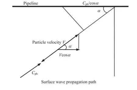
Fig.2.Resolution of particle and phase velocities along the pipeline axial direction for R-waves.
3.1.Surface wave interaction with JCCPs
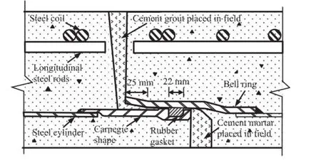
Fig.3.Schematic view of JCCP joint.
O’Rourke et al.(2004)developed both FE and analytical models for estimating the axial strain in a continuous pipeline and relative displacement of an unrestrained joint under seismicwave interaction.Fig.4 shows an incremental section of continuous buried pipeline,dx,subjected to a seismic wave,simplifed as a sinusoidal wave with the maximum amplitude of ground strain εgmax=Vp/Ca,whereVpis the peak ground particle velocity.
Defningfas the maximum shear transfer between soil and pipe wall in unit pipe length,Eas the pipe material modulus,Aas the pipe cross-sectional area,EAas the pipe axial stiffness,andRas the ratio ofVp/Cato the rise distance,λ/4,Shi and O’Rourke(2008)and Wang and O’Rourke(2008)proposed whenf/(EAR)≥1,the pipeline is relatively fexible with respect to ground deformation induced by seismic waves.A relatively fexible pipeline deforms axially in the same way as the ground deforms such that εpmax/εgmax=1,where εpmaxis the maximum strain in a continuous pipeline.Shi and O’Rourke(2008)and Wang and O’Rourke(2008)also proposed whenf/(EAR)<1,the pipeline is relatively rigid,the pipe strain is less than the ground strain,and εpmax/εgmax<1.
When surface waves propagate along the JCCPs,due to the relatively low phase velocity of the surface waves,the strain accumulation rate of the pipeline is typically lower than the ground strain accumulation rate.The pipeline is relatively rigid.Fig.5 shows the seismic response of a relatively rigid pipeline with a locally weak joint under the action of surface waves.When surface waves propagate along the pipeline,the ground movement transfers shear force to the pipeline.The shear transfer is shown in Fig.5a with small arrows indicating its direction.The axial force in the pipeline is the integration of the shear transfer along the pipe length.The axial force increases from zero where the ground strain is zero to its maximumfλ/4 after a quarter of wavelength of shear accumulation.When the maximum tensile force in the pipeline exceeds the tensile capacity of the locally weak joint,the joint cracks.The axial tensile force at the pipe ends,connected with the joint,drops to zero,and the pipeline sections at both ends of the cracked joint tend to move away from each other.The ground at the cracked joint has zero displacement as shown in Fig.5b.In the vicinity of the cracked joint,the pipe displacement is larger than the ground displacement and the shear transfer from the ground to pipeline tries to prevent the pipeline sections from moving away from each other until the ground displacement equals the pipe displacement at pointA.Beyond pointA,the ground displacement is larger than the pipe displacement and the shear transfer direction reverses.The integration of the differential strain between pipeline and soil from the cracked joint to the shear transfer reversal point,A,is represented by half of the shaded area in Fig.5a. It is the relative displacement between the pipeline and ground at the cracked joint,which equals one half of the relative joint displacement.For seismic wave interaction with a relatively rigid pipeline,the relative joint displacement is determined by soilstructure interaction and is analyzed by FE methods.
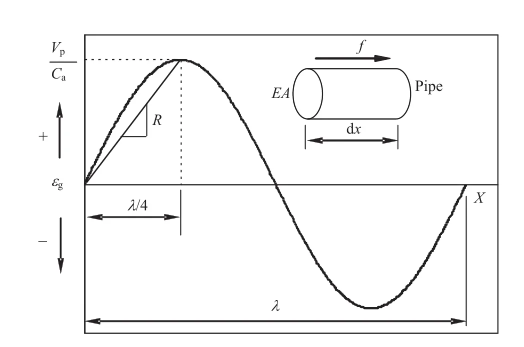
Fig.4.Sinusoidal wave interaction with pipe element(modifed after O’Rourke et al., 2004).
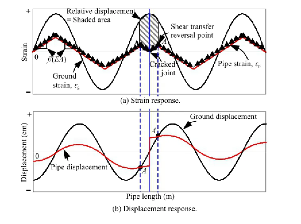
Fig.5.Sinusoidal wave interaction with a relatively rigid pipeline with a cracked joint.
3.2.FE simulation
FE analyses of surface wave interaction with JCCPs were performed using the program BSTRUT(Chang,2006).Fig.6 shows the FE model in which the pipeline was modeled with beam column elements that were connected to the ground by spring-slider elements capable of representing shear transfer as an elastoplastic process.The locally weak joint in the JCCP was modeled as a springslider element with a zero length and very low axial pullout resistance that for modeling purposes can be negligible.The FE model was composed of 1666 pipe elements and 1669 spring-slider elements over a distance of roughly 10 km for an element length of 6 m.
The strong motion recording at Central de Adastos-Ofcinas during the 1985 Michoacan earthquake in Mexico City,as shown in Fig.1,was used as ground motion inputs.Time records of strong motion were converted to displacement versus distance records by assuming thatx=Cpht,in whichxis the distance,andtis the time from the strong motion recording.The phase velocity,Cph,is taken as 120 m/s and the predominant period is 3.5 s.The seismic displacement versus distance record was superimposed on the spring-slider elements,which then conveyed the ground movement to pipeline.When the maximum slope of the displacement versus distance record(corresponding to the maximum ground particle velocity in the velocity record)was superimposed on the weak pipeline joint,the maximum axial slip of the joint was calculated.
The FE analysis was used to evaluate the performance of the 1829-mm-diameter jointed concrete Federal District transmission line in Mexico City,which was severely damaged during the 1985 Michoacan earthquake due to surface WP effects(Ayala and O’Rourke,1989).The pipeline is assumed to be buried in trench with a burial depth of 2 m measured from ground surface to pipe center.The backfll material surrounding the pipeline is assumed as sandy soil with a unit weight of 18.9 kN/m3and a frictional angle of 35°.The soil-pipe interface friction angle is assumed tobe the same as the soil frictional angle.
As recommended by the American Lifeline Alliance(ALA,2005), Fig.7 shows the relation between unit shear transfer and relative pipe-soildisplacement,whichwasmodeledasabilinearrelationship with a linear rise tofat a relative displacement of δs=3 mm and constantfthereafter.Values offare calculated according to the procedures summarized by O’Rourke(1998)for cohesionless backfll:

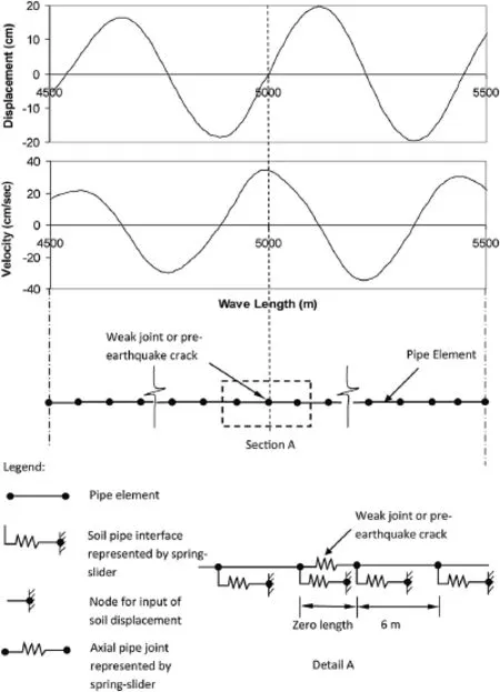
Fig.6.FE model for seismic wave interaction with pipeline.
wherezpis the burial depth to pipe centerline,γis the soil unit weight,K0is the coeffcient of at-rest horizontal soil stress (assumed as 0.5 in this calculation),δis the angle of interface frictional resistance,andDis the pipe outside diameter.
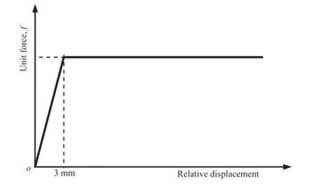
Fig.7.Elastoplastic model of shear transfer.
The unit shear transfer,f,is calculated as 39.5 kN/m and the value off/(EA)is calculated as 4.1×10⁻⁶m-1.It was assumed that the pipeline is orientated inparallel with the direction of WP,which results in the maximum joint pullout.Fig.8 shows the displacement and strain of ground soil and pipeline in the vicinity of the locally weak joint.The pipeline is not able to deform together with the ground soil and exhibits relatively rigid behavior.The relative joint displacement is the shaded area and is calculated as 16 cm. The high predicted relative joint displacement indicates a strong potential for joint pullout and disengagement of JCCPs under surface wave effects.
3.3.Dimensionless plot
Shi and O’Rourke(2008)and Wang and O’Rourke(2008)performed parametric studies of different pipe properties,seismic wave characteristics,and ground conditions,and summarized the results in Fig.9 with two dimensionless parameters,δ/δ0andf/(EAR).The parameterδ0is defned as the area under the seismic sinusoidal ground strain pulse and can be calculated asδ0=VpT/π, whereTis the predominant period of the seismic wave.The dimensionlessparameter,δ/δ0,indicatestherelativejoint displacement normalized with respect to a displacement index of the seismic wave characteristics.The dimensionless parameter,f/(EAR),represents a combination of key ground conditions,pipeline properties,and seismic wave characteristics.
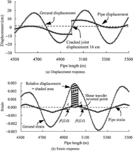
Fig.8.FE simulations of JCCP response to surface wave propagation effects.
When affected by body waves,pipelines generally exhibit relatively fexible behavior because the high apparent wave velocity drives the ground strain accumulation rate to be lower than the pipeline strain accumulation rate.When affected by surface waves,pipelines can be either relatively fexible or rigid.The behaviors of a relatively fexible pipeline under seismic wave effects can refer to O’Rourke et al.(2004)and Wang and O’Rourke (2008).
Withknownground conditions,pipelineproperties,and seismic wave characteristics,the values off/(EAR)andδ0can be calculated and joint displacement,δ,can be estimated directly using Fig.9.This chart can be used to facilitate the computation of the joint pullout movement of any conventional JCCPs affected by any seismic waves virtually.For the example used above,withVp=35 cm/s,Cph=120 m/s,T=3.5 s,λ=120 m/s×3.5 s=420 m,R=(Vp/Cph)/(λ/4)=2.78×10-5m-1,thenf/(EAR)=4.1×10-6/ (2.78×10⁻⁵)=0.148.From Fig.9,forf/(EAR)=0.148,δ/δ0=0.42, δ0=VpT/π=39 cm,thenδ=0.42×39 cm=16.4 cm,which has a difference of about 2%from 16 cm resulting from the FE simulation.More examples on the application of the dimensionless chart can refer to Shi and O’Rourke(2008)and Wang and O’Rourke (2008).
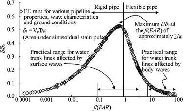
Fig.9.Dimensionless plot betweenδ/δ0andf/(EAR).
3.4.Concrete cracking effects
In previous section,it is assumed that the joints on either side of the cracked joint have full mortar connectivity to allow pipestraintoaccumulateacrossthejoints.Theconcrete mortar,poured in feld to seal joints,will be cracked when the straininthejointsexceedsitscrackingstrainlimit.The cracking of the concrete mortar will change the geometry of the pipeline and reduce the strain accumulation length.The joint displacement,therefore,is closely related to the concrete cracking strain.In this section,the effect of concrete cracking strain is explored.
Fig.10 illustrates the seismic ground strain interaction with a JCCP.Each partof Fig.10 shows the groundstrain,εg=V/Cph,plotted on the vertical axis.The horizontal axis plots the distance,x=Cpht,along the longitudinal axis of the JCCP.The velocity pulse shown in Fig.10 corresponds to half of a sinusoidal wave which develops tensile strains in the ground.
Fig.10 shows the evolution of a seismic wave at various times,t0throught4,as it approaches and moves into the ground surrounding a JCCP that terminates at an anchor point.When the seismic wave intersects with the pipeline,the strain begins to accumulate from pointOwith a slopef/(EA).Because the pipeline is relatively rigid,the pipe strain accumulation rate is slower than the ground strain accumulation rate,so the slope isf/(EA)everywhere on the pipeline untilt1,when the frst joint next to the anchor point reaches its tensile strain capacity,εp=(FJ+Lf/2)/(EA)=1.14×10-4, whereFJis the tensile capacity of normal joints and cracks (Fig.10b).
At the cracked joint,we have εp=0.To satisfy the force equilibrium,the strainwill accumulate fromthe pointOand the cracked joint,both of which havef/(EA),with the same slope of εp=(FJ+Lf/ 2)/(EA)=1.14×10-4,but in opposite directions,until εp=εT/2, where εTis the cracking strain at the joint.Therefore,at the middle of the pipe section between the cracked joint and pointO,the shear transfer is zero and the pipe displacement is equal to the ground displacement.
The shaded area in Fig.10b represents the integration of the differential strain between the pipeline and ground,which equals the relative joint displacement.In a similar fashion,the shaded areasinthesubsequentfguresrepresentrelativejoint displacement.As the seismic wave propagates,another joint on the left of the frst cracked joint exceeds its tensile strain limit att2(Fig.10c)and cracks at timet3(Fig.10d),which happens immediately aftert2.The distance between these two joints,L, can be determined by

whereVTis the particle ground velocity at which the ground strain is equal to εT,i.e.VT=εTCph.
On the right side of the newly cracked joint,the pipeline segment has zero strain at two cracked ends.To satisfy equilibrium, the strainwill accumulate linearly fromboth ends at the same slope off/(EA),until εp=εT/2.As the same reason,on the left side of the newly cracked joint,the strain will also accumulate linearly from both ends at the same slope off/(EA),until εp=εT/2.With continuous WP,the next joint will crack at a distance,L,left of the previously cracked joint(Fig.10e).This process repeats as the wave moves forward along the pipeline.
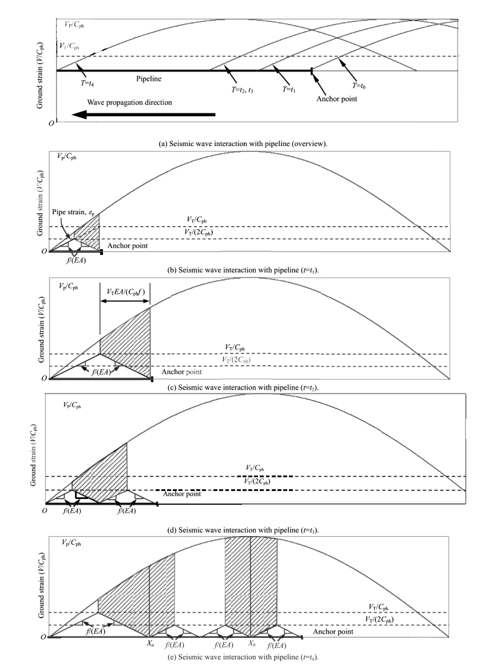
Fig.10.Surface wave interaction with a JCCP considering concrete cracking effects.
The two most critical cases for relative joint displacement are illustrated in Fig.10e.The relative joint displacement attains its frst local maximum atXajust before another joint left ofXacracks.The relative joint displacement,δa,can be calculated from the shaded area on the left of Fig.10e.The shaded area on the right of Fig.10e atXbillustrates the second possible maximum joint displacement,δb. This movement occurs when the PGV,Vp,passes across the cracked joint.The maximum relative joint displacement is larger than the two possible joint displacements.
Fig.11 illustrates a simplifed procedure for calculating the shaded areas in Fig.10e.The relative joint displacement for the frst potential maximum,δa,could be calculated by the integral of ground strain along a distance from(VT/Cph)(EA/f)to 5(VT/Cph)(EA/f)/2,subtracting the areas of triangles 1 and 2.Theintegral of the ground strain from(VT/Cph)(EA/f)to 5(VT/Cph)(EA/f)/2 is

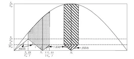
Fig.11.Simplifed view of seismic wave interaction with a rigid pipeline.
The areasA1andA2are calculated as

Substituting εT=VT/Cphandλ=CphTinto Eqs.(4)-(6)results in

Similarly,the relative joint displacement for the alternative maximum,δb,can be decomposed into two area components:

where

Substituting εT=VT/Cphinto Eqs.(9)and(10)results in

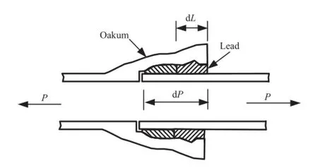
Fig.12.Schematic drawing of bell-and-spigot lead caulked joint.
Based on above analysis,when the maximum strain in a relatively rigid pipeline exceeds the limit of concrete cracking strain, the largest relative joint displacement is chosen from either Eq.(7) or Eq.(11).When the maximum strain in the pipeline is smaller than the concrete cracking strain,the relative joint displacement can be estimated using the universal relationship provided in Fig.9.
The cracking strain for concrete mortar ranges from 5×10⁻⁵to 1.5×10⁻⁴(Avram et al.,1981)with a typical value of 1×10⁻⁴.For the pipeline and surface wave used in Section 3.2,the maximum strain in the pipeline is calculated as[f/(EA)](λ/4)=4.3×10-4, which is larger than the cracking strain of concrete mortar.By accounting for the cracking of concrete mortar and choosing the cracking strain as 1×10⁻⁴,the joint displacements calculated by Eqs.(7)and(11)are 6.3 cm and 7 cm,respectively.Thus,the larger value,7 cm,provides a reasonable estimate of the axial joint slip for a segmented JCCP in the feld.This value is larger than the pullout capacity of the rubber gasket joint,which ranges typically from 2 cm to 5 cm.By accounting for the pipe orientation effects,it explains well that some of the rubber gasket joints with unfavorable orientation would be disengaged in the 1985 Michoacan earthquake.Joints with favorable orientation only had minor or no leakage with different degrees of loss of gasket compression.
The model presented in this section accounts for cracking where the tensile capacity of the pipeline joint is exceeded,and therefore is compatible with strain limits of the pipeline material.The cracking of joints transforms the pipeline from a continuous structure to a segmented one.The model,therefore,accounts for geometric nonlinearity.It is able to track changes in geometric properties,shear transfer,pipeline strain accumulation,and joint displacement during seismic wave propagation along the pipeline.
4.Surface wave interaction with CI pipelines
The previous section presents the surface WP effects on JCCPs which are composed of joints with brittle tensile failure behavior. This section discusses the surface WP effects on the CI pipelines which are composed of joints with ductile tensile behavior.
4.1.Characteristics of CI pipelines
The CI pipeline is one of the oldest and most commonly used segmented pipelines for water and gas transportation.The CI pipelines are typically composed of 3-6 m long pipe segments, jointed together with bell-and-spigot lead caulked joints.Fig.12 shows a schematic drawing of the joint.Fig.13 summarizes axial force vs.displacement data after Prior(1935)from a comprehensive testing program of lead caulked joints for water trunk and distribution pipelines.The axial force is expressed in terms of kN per circumferential distance.Two force-displacement models are provided corresponding to rigid and elastoplastic behaviors, respectively.Both models show that a very small axial displacement,0 for rigid and 2.5 mm for elastoplastic model,is needed to mobilize the full axial tensile capacity of the joints.The axial slip that the joint can sustain without reducing its tensile resistance depends on the depth of oakum packing,which typically ranges from 50 mm to 75 mm.The pullout capacity of the joint in terms of axial displacement to cause leakage depends on how much movement can occur before the lead caulking loses its compressive seal.El Hmadi and O’Rourke(1990)summarized the available information on joint performance and suggested a relative joint displacement corresponding to 50%of the total joint depth to cause leakage.The total joint depth typically ranges from 100 mm to 140 mm for pipe diameter ranging from 41 cm to 122 cm,resulting in an axial pullout movement of 50-70 mm to cause leakage.
4.2.Surface wave interaction with CI pipelines
For CI pipelines with ductile joints,the tensile force at both ends of the pipe barrel is limited by the joint tensile capacity which establishes the pipe barrel axial strain limit,above which further elongation occurs as joint axial slip.Furthermore,the joint capacity varies from joint to joint,due to the uncertainties associated with caulking and sealing materials,workmanship during installation, subsequent movements from external operation and/or thermal loads.The relative joint displacement during earthquakes is a consequence of variable pullout resistance among joints in a pipeline and is estimated using FE model.
The similar FE model as illustrated in Fig.6 is used to simulate the CI pipeline performance except that only one locally weak joint is modeled in the JCCP simulation in Fig.6 while every joint is modeled in the CI pipeline simulation.The joints are modeled as elastoplastic springs.The interrelation between joint pullout resistance and relative displacement is modeled as an elastoplastic process with linear rise to the joint tensile capacityFJat a relative displacement ofδJ=2.5 mm and constantFJthereafter.The variability of joint tensile capacity is considered by assuming all joints with the same capacity,except one locally weak joint with a reduced capacity.The weak joint has the lowest pullout resistance in the pipeline.Therefore,the highest joint pullout displacement will occur when the seismic wave peak tensile strain pulse passes the weak joint.Parametric studies are performed to the weak joint capacity which varies from the capacity of normal joints to 0.
The FE model is used to model the interaction of a 610-mm outside diameter,22.4-mm wall thickness CI pipeline interacting with a surface wave withVp=30 cm/s,Cph=120 m/s andT=3.5 s. The pipeline burial depth is 1 m to pipe crown.The surrounding soil is cohesionless backfll with a unit weight of 18.9 kN/m3and frictional angle of 35°.The soil-pipe interface frictional angle is assumed as 30°.The tensile capacity of joints is calculated as 287 kN using a pipe diameter of 610 mm and a normalized tensile capacity of 0.15 kN/mm of circumferential distance as provided in Fig.13.The FE model is composed of 800 pipe elements,1600 spring-slider elements to model soil-pipe interface,and 800 spring elements to model joints over a distance of 3.66 km for a pipe segment length of 4.57 m.
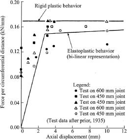
Fig.13.Axial force vs.displacement data for lead caulked joints(after Prior,1935).
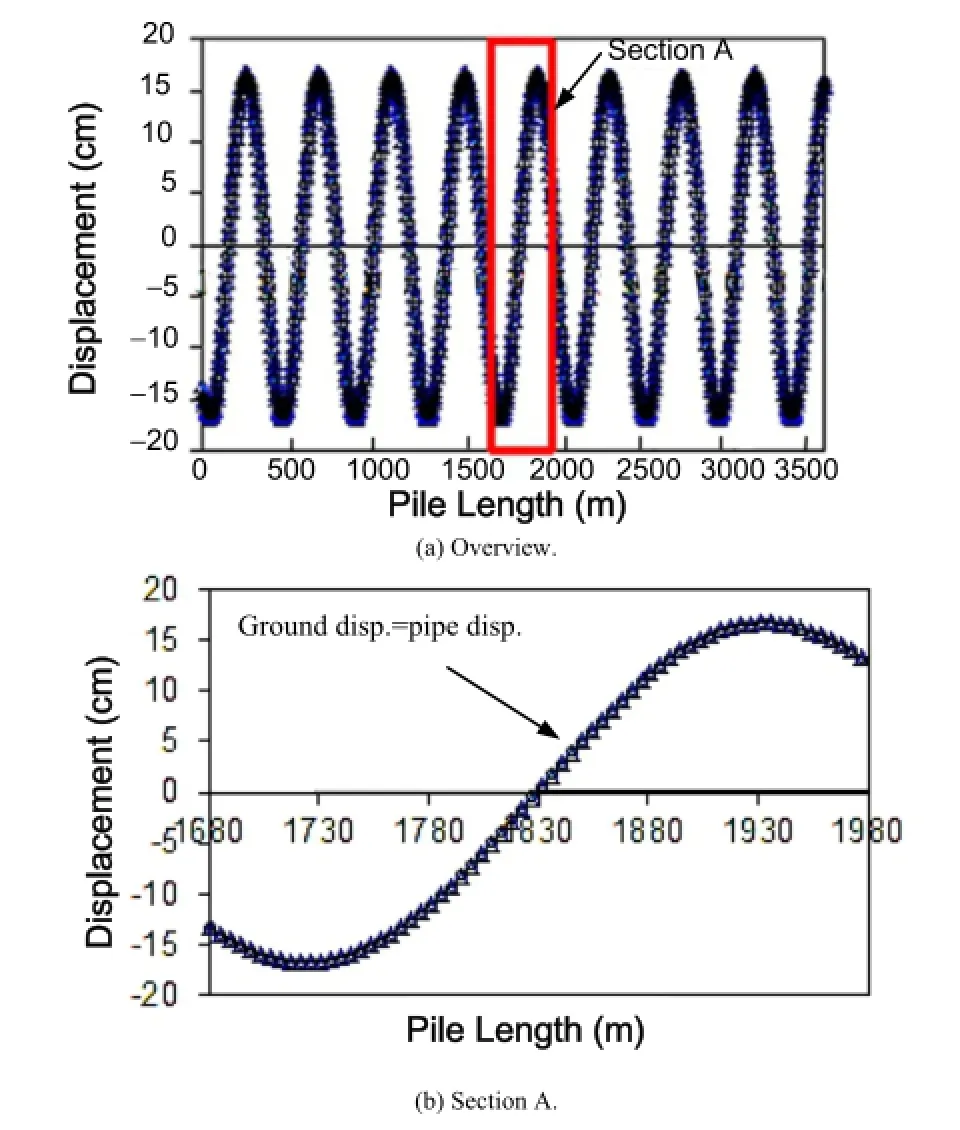
Fig.14.Ground and pipe displacements when all joints have the same tensile capacity.
Figs.14-16 show the seismic response of the CI pipeline when the weak joint has the same tensile capacity as the normal joint,i.e.FW=FJ=287 kN,whereFWis the tensile capacity of weak joint. Fig.14 plots the displacement of pipe segment and ground at the locations of each pipe segment center.Same as Figs.14-19,both anoverview along the entire pipeline and a detailed view in the middle part of the pipeline are presented.Fig.14 shows that,due to the low axial stiffness of the joints,the pipeline deforms together with ground and the pipe displacement is equal to ground displacement at each pipe segment.The ground strain along segmented pipelines is accommodated by a combination of pipe strain and relative axial displacement at joints.
Fig.15 shows the strain in pipe barrels.The pipe strain increases linearly from 0,where the ground strain equals 0,until the axial force in the joint reaches the joint tensile capacity.Thereafter,the strain cannot accumulate linearly along the whole pipe segment because the axial strain at both ends of pipe barrel is limited by the joint capacity and is equal toFJ/(EA).The strain can only accumulate from both ends of the pipe barrel at a rate off/(EA),with different directions towards the middle of the pipe barrel,where the strain reaches its maximum value,and the direction of strain accumulation reverses.The maximum strain at the middle of pipe barrel can be approximated as εp=(FJ+Lf/2)/(EA)=1.14×10-4.The pipe strain is a local maximum at the middle of the pipe segment,which means there is no relative displacement between pipe and ground at the middle of the segment.The same situation happens to every pipe segment until the joint axial force is smaller thanFJ/(EA).
Fig.16 shows the relative joint displacement along the pipe length.The relative joint displacement increases linearly from 0 to 2.5 mm(the elastic displacement limit of the joint),after which its variation follows a sinusoidal curve trend.The maximum joint displacement occurs at the locations where the ground strain reaches peak and is relatively small(1.1 cm).
Figs.17-19 show the seismic response of the pipeline when the tensile capacity of the locally weak joint is reduced to 57 kN,1/5 of 287 kN,the tensile capacity of normal joints.Fig.17 shows the displacements of pipeline and ground.This fgure shows that the pipeline deforms together with the ground except in the vicinity of the weak joint.At the weak joint,the ground displacement is 0 andthe pipe displacement is higher than the ground displacement.The relative displacement between pipe ends and ground occurs as the pullout movement of the weak joint.
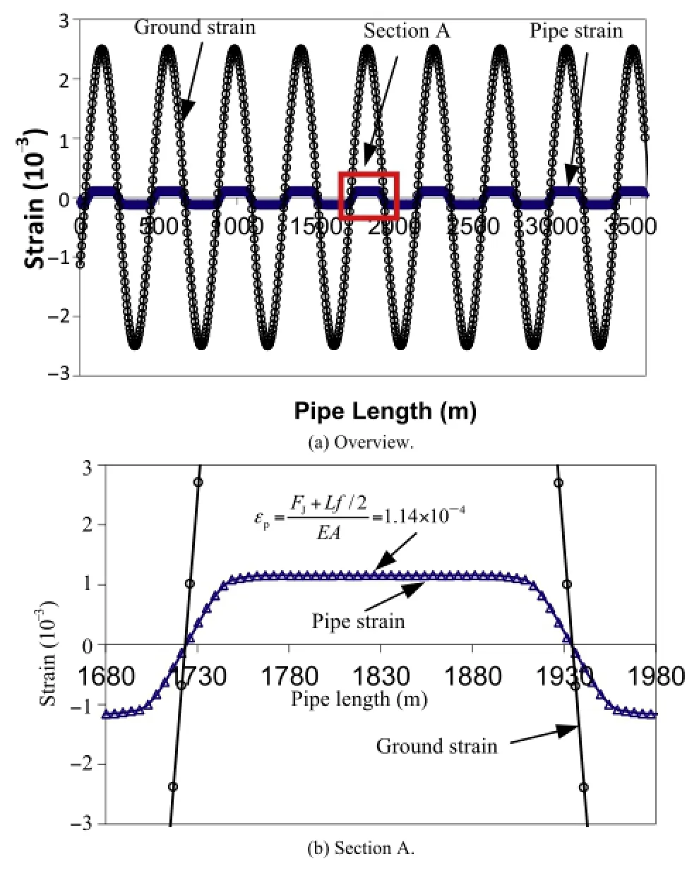
Fig.15.Ground and pipe strains when all joints have the same tensile capacity.
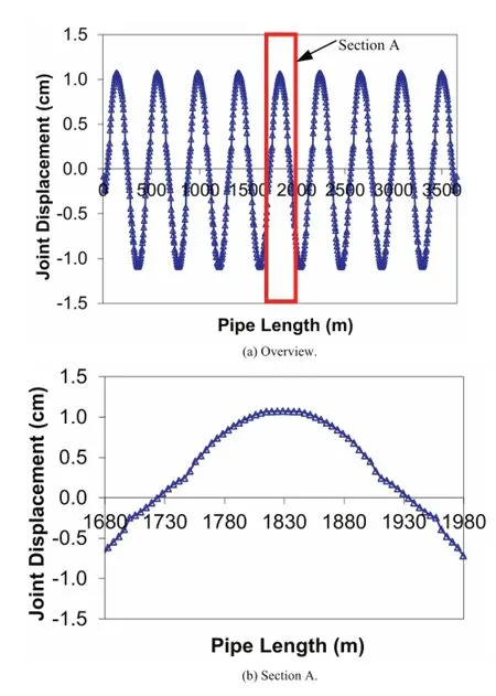
Fig.16.Relative joint displacement when all joints have the same tensile capacity.
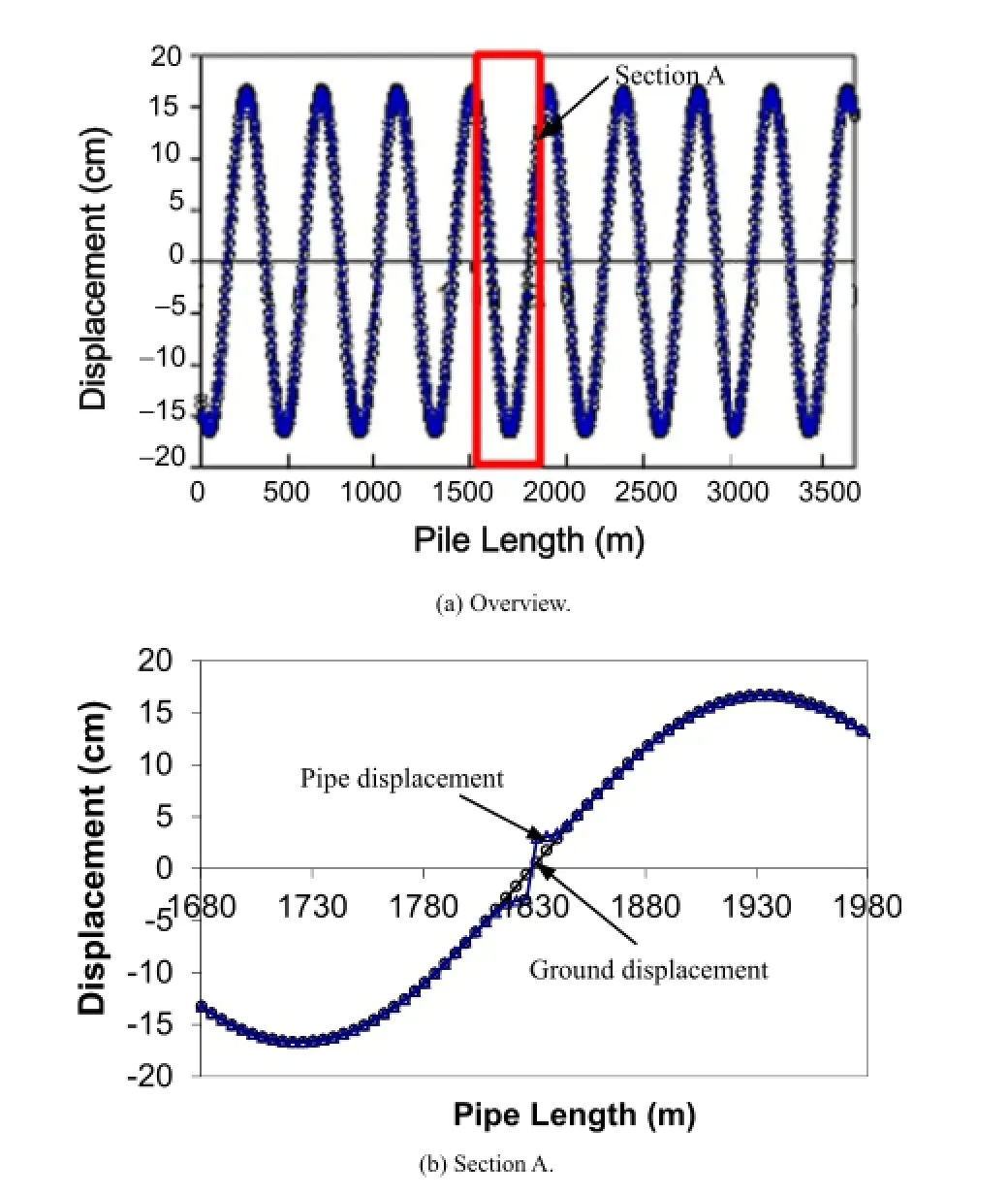
Fig.17.Ground and pipe displacements with one locally weak joint.
Fig.18 shows the strain of pipe barrels.As the seismic wave passes across the weak joint,axial strain in the barrel on either side of the weak joint accumulates linearly from εp=FW/(EA)= 1.98×10⁻⁵,with a slope off/(EA)until εp=(FJ+Lf/2)/ (EA)=1.14×10⁻⁴.The integration of the differential strain between pipe barrel and the ground from the weak joint to the middle point of the pipe barrel,pointAin Fig.18b,at which the pipe displacement reaches the ground displacement frst time,as represented by half of the shaded area in Fig.18b,is the relative displacement between the pipe barrels and ground,which occurs as the displacement of the joint,connecting adjacent pipe barrels.
Fig.19 shows the relative displacement of joints along the pipe length.This fgure shows that,in the vicinity of the locally weak joint,the joint displacement accumulates at the locally weak joint, resulting in a large joint displacement,5.9 cm,at the locally weak joint but very small displacements of other joints.The joint with a relative displacement of 5.9 cm would likely be a leak.
Fig.20 shows the relationship between the relative joint displacement and the tensile capacity of the weak joint for different seismic waves,characterized by the peak ground strain.The capacity of the weak joint is normalized with the capacity of normal joints.The relative joint displacement approximately linearly increases with the reduction of the capacity of the locally weak joint. The joint displacement reaches its maximum when the weak joint has zero tensile capacity.
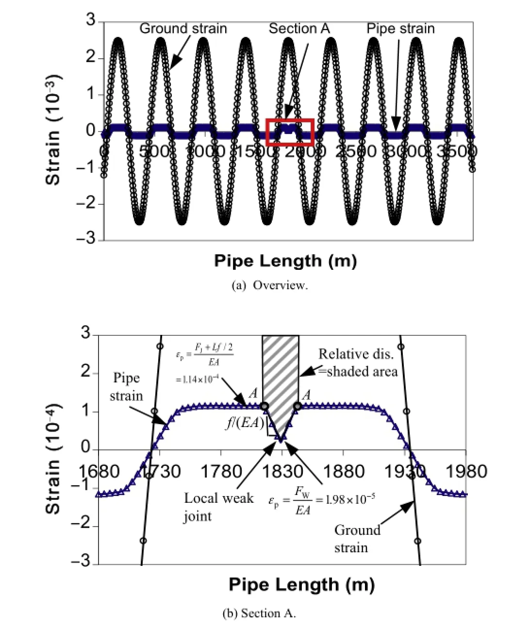
Fig.18.Ground and pipe barrel strains with one locally weak joint.
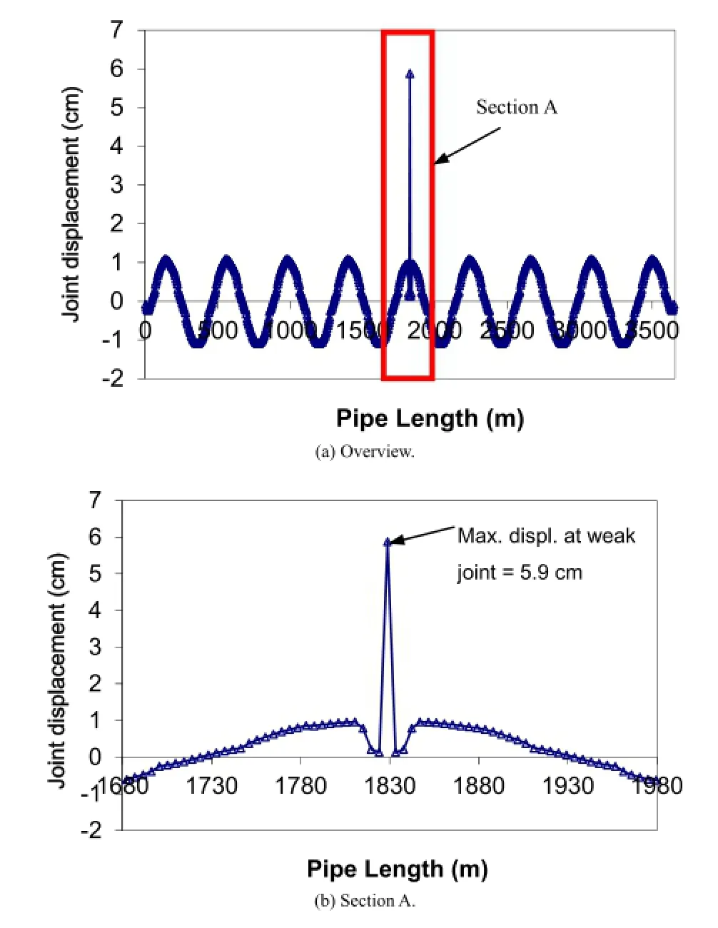
Fig.19.Relative joint displacement with one locally weak joint.
4.3.Simplifed analytical equation for the maximum joint pullout
When there is a locally weak joint with reduced tensile capacity in the pipeline,the relative displacement between pipe barrels and ground,asshownintheshadedareainFig.18b,isaccommodatedby the axial displacement of the joints in the vicinity of the weak joint. The axial displacement of joints accumulates at the weak joint.The axial displacement of joints next to the locally weak joint is within the elastic region and is relatively small.A parametric study shows that when the peak ground strain is higher than 0.001,the axial displacement of the normal joints can be neglected and the shaded area can be approximated as the displacement of the locally weak joint.Fig.21 provides an estimate of the relative joint displacement, δj,which can be decomposed into two area components:

where

Please note thatA1is simplifed as a rectangle with the height ofVp/Ca-(FJ+Lf/2)/(EA).The error associated with this simplifcation is very small,less than 5%.
Combination of Eqs.(12)-(14)results in

Eq.(15)shows the relative joint displacement is a function of ground strain,capacity of the normal joint and weak joint,pipesegmental length,pipe axial stiffness,and unit shear transfer.The error of the analytical results increases with the decrease in peak ground strain.The error is about 25%when the peak ground strain is about 0.001.Thus it is proposed to use the simplifed equation to estimate the axial displacement of the weak joint when the peak ground strain is higher than 0.001.
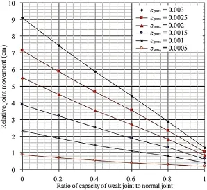
Fig.20.Relationship between weak joint capacity and relative joint displacement.
5.Conclusions
In this paper,both analytical and FE models are developed to analyze the joint pullout movement of JCCPs and CI pipelines under surface WP effects.When surface waves propagate along JCCPs,the JCCPs typically perform as a relatively rigid pipeline which cannot deform together with the ground.The joint displacement of a relatively rigid pipeline is determined by soil-structure interaction and can be estimated by FE simulation.A relative joint displacement as large as 16 cm is predicted for a 1829-mm-diameter JCCP interacted with surface waves from strong motion recording during the 1985 Michoacan earthquake,assuming that the joints on either side of the cracked joint have full mortar connectivity to allow pipe strain to accumulate across the joints.The high predicted relative joint displacement indicates strong potential for joint pullout affected by surface waves.
By accounting for the cracking of concrete mortar,the relative joint displacement will be reduced signifcantly,because the cracking of the joints will not allow suffcient pipe length for the strain accumulation.Simplifed analytical solutions are provided for estimating the maximum joint pullout considering the concrete cracking effects.Roughly 7 cm of relative joint displacement is estimated for the 1829-mm-diameter JCCP under the interaction with surface waves recorded during the 1985 Michoacan earthquake.This amount of relative joint displacement will cause the disengagement of the JCCP joints and is consistent with the feld observations.
The relative joint displacement of CI pipelines is mainly affected by the variability of the joint tensile capacity.When all the joints have the same tensile capacity,the maximum joint displacement is relatively small,about 1 cm,for the examples used in this study. When there are locally weak joints with reduced tensile capacity in the pipeline,the joint displacement accumulates at the locally weak joints.The displacement of the locally weak joints increases almost linearly with the reduction of its tensile capacity.Simplifed analytical equation is developed for estimating the pullout movement of locally weak joints.
Confict of interest
The author wishes to confrm that there are no known conficts of interest associated with this publication and there has been no signifcant fnancial support for this work that could have infuenced its outcome.
Acknowledgments
This research was funded by the Earthquake Engineering Research Centers Program of the National Science Foundation (NSF),under grant number EEC-9701471,through the Multidisciplinary Center for Earthquake Engineering Research(MCEER).The fnancial support from the NSF and MCEER is gratefully acknowledged.The author would like to thank Prof.O’Rourke at Cornell University and Prof.Yu Wang at the City University of Hong Kong for their contributions to the work.
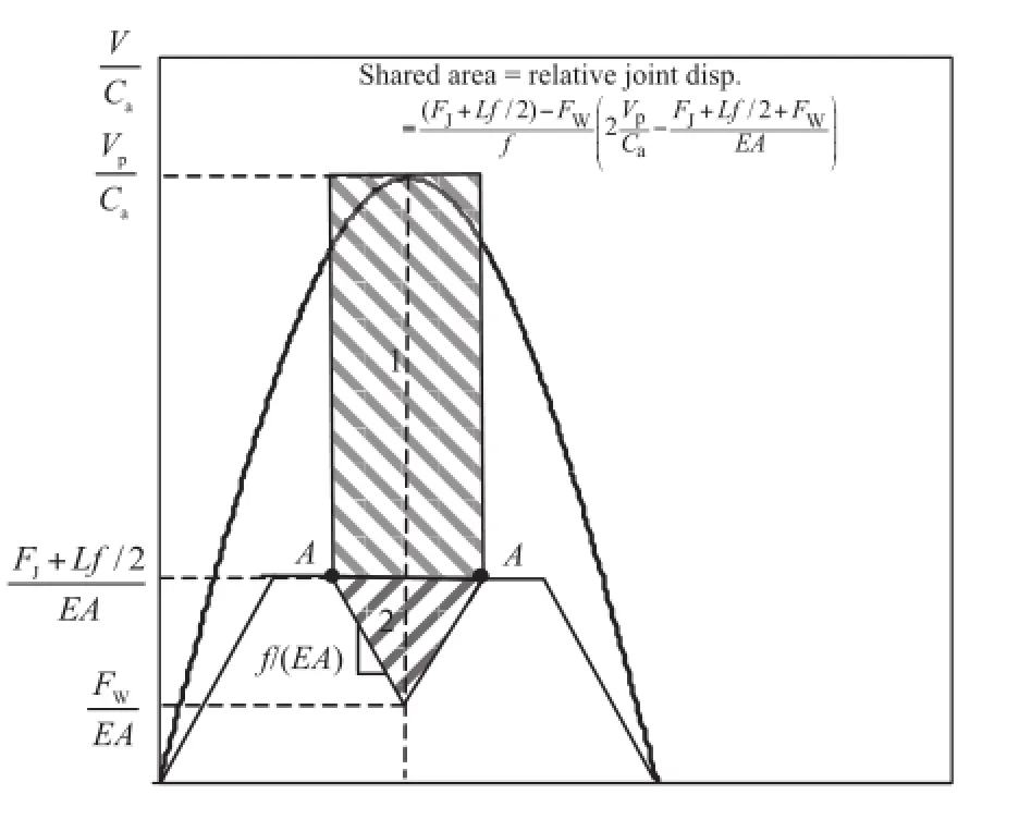
Fig.21.Simplifed model for seismic wave interaction with CI pipelines with one locally weak joint.
American Lifeline Alliance(ALA).Design guidelines for seismic resistant water pipeline installations.FEMA and National Institute of Building Sciences, 2005.
Avram C,Facaoaru I,Filimon I,Mirsu O,Tertea I.Concrete strength and strains. Elsevier Science Ltd.;1981.
Ayala AG,O’Rourke MJ.Effects of the 1985 Michoacan earthquake on water system and other buried lifelines in Mexico City.Technical Report NCEER-89-0009. New York,USA:Multidisciplinary Center for Earthquake Engineering Research; 1989.
Chang JF.P-Y modeling of soil-pile interaction.PhD Thesis.Ithaca,USA:School of Civil and Environmental Engineering,Cornell University;2006.
El Hmadi K,O’Rourke MJ.Seismic damage to segmented buried pipelines.Earthquake Engineering and Structural Dynamics 1990;19(4):529-39.
Iwamoto T,Wakai N,Yamaji T.Observation of dynamic behavoir of ductile iron pipelines during earthquakes.In:Proceedings of the 8th World Conference on Earthquake Engineering,Vol.VII.San Francisco,USA;1984. p.231-8.
Newmark NM.Problems in wave propagation in soil and rock.In:Proceedings of the International Symposium on Wave Propagation and Dynamic Properties of Earth Materials.Albuquerque,USA:University of New Mexico Press;1967.p.7-26.
O’Rourke MJ,Liu X.Seismic design of buried and offshore pipelines.Technical Report MCEER-12-MN04.Buffalo,USA:Multidisciplinary Center for Earthquake Engineering Research;2012.
O’Rourke TD.An overview of geotechnical and lifeline earthquake engineering.In: Proceedings of Geotechnical Earthquake Engineering and Soil DynamicsConference.Reston,USA:American Society of Civil Engineers(ASCE);1998. p.1392-426.
O’Rourke TD.Geohazards and large geographically distributed systems.Geotechnique 2010;60(7):503-43.
O’Rourke TD,Wang Y,Shi P.Advances in lifeline earthquake engineering.In:Proceedings of the 13th World Conference on Earthquake Engineering,Vancouver, Canada;2004.Paper No.5003.
Papageorgiou AS,Kim J.Propagation and amplifcation of seismic waves in 2-D valleys excited by obliquely incident P-and SV-waves.Earthquake Engineering and Structural Dynamics 1993;22(2):167-82.
Prior JC.Investigation of bell and spigot joints in cast iron water pipes.Bulletin 87. Ohio State University;1935.
Shi P,O’Rourke TD.Seismic response modeling of water supply systems.Technical Report MCEER-08e0016.Multidisciplinary Center for Earthquake Engineering Research;2008.
Wang LRL.Some aspects of seismic resistant design of buried pipelines.In: Lifeline earthquake engineering:buried pipelines,seismic risk,and instrumentation(PVP-34).AmericanSocietyofMechanicalEngineers;1979. p.117-31.
Wang Y,O’Rourke TD.Seismic performance evaluation of water supply systems. Technical Report MCEER-08e0015.Multidisciplinary Center for Earthquake Engineering Research;2008.

Dr.Peixin Shiis a professor in the School of Urban Rail Transportation at Soochow University.He obtained his BS degree in Civil Engineering at Beijing Jiaotong University in 1998,MS degree in Geotechnical Engineering at the same university in 2001,and Ph.D.degree in Georechnical Engineering at Cornell University in 2006.Before joining Soochow University,Dr.Shi worked as a senior geotechnical and tunneling engineer in Parsons Brinkerhoff New York offce from February 2006 to November 2013.As a registed professional engineer in USA,he has extensive experience in the design of geotechnical and underground structures includingroadwaypavement,railroadembankment, shallow and deep foundations,cut-and-cover tunnels,TBM tunnels,immersed tube tunnels,and large underground caverns.Dr.Shi is also capable of managing large underground infrastructure constructions after serving as the construction manager for two subway projects in New York City.He had worked on several multi-billion geotechnical and tunneling projects including Eurasian Tunnel,Istanbul,Turkey;Elizabeth River Tunnels,Virginia,US;Second Avenue Subway,New York,US;Trans-Hudson Express Tunnels,New Jersey,US; East Side Access,New York,US,etc.His current research interests include lifeline earthquake engineering,risk assessment of urban tunnel and underground cavern construction,ballasting resistant tunnel and cavern design,and aseismic design of subsea tunnels.He has authored/co-authoredover 30publications.Hisresearchwork on earthquake simulation of water supply system has been published as a monograph by the Multidisciplinary Center for Earthquake Engineering Research(MCEER).
*Tel.:+86 13511601281.
E-mail address:pxshi@suda.edu.cn.
Peer review under responsibility of Institute of Rock and Soil Mechanics,Chinese Academy of Sciences.
1674-7755©2015 Institute of Rock and Soil Mechanics,Chinese Academy of Sciences.Production and hosting by Elsevier B.V.All rights reserved.
http://dx.doi.org/10.1016/j.jrmge.2015.02.011
 Journal of Rock Mechanics and Geotechnical Engineering2015年4期
- Journal of Rock Mechanics and Geotechnical Engineering的其它文章
- A theoretical derivation of the Hoek-Brown failure criterion for rock materials
- Strength properties of soft clay treated with mixture of nano-SiO2and recycled polyester fber
- Case studies of high-sensitivity monitoring of natural and engineered slopes
- Key technologies of drilling process with raise boring method
- Analysis of horizontal displacement distribution caused by single advancing longwall panel excavation
- Susceptibility assessment of debris fows using the analytic hierarchy process method-A case study in Subao river valley,China
