Case studies of high-sensitivity monitoring of natural and engineered slopes
Werner Lienhart
Graz University of Technology,Graz,Austria
Case studies of high-sensitivity monitoring of natural and engineered slopes
Werner Lienhart*
Graz University of Technology,Graz,Austria
A R T I C L E I N F O
Article history:
Received 19 December 2014
Received in revised form
28 February 2015
Accepted 2 April 2015
Available online 8 May 2015
Structural health monitoring
Fiber optic sensors
Brillouin optical frequency domain analyzer
(BOFDA)
SOFO sensors
Reinforced earth structures
Geogrid
Landslides
High-sensitivity monitoring solutions are crucial for early warning systems of earth structures.In this paper,we discuss the design and implementation of such systems for natural and engineered slopes using two case studies.At the Gradenbach Observatory,one key element of the monitoring system is a large fber optic strain rosette embedded in the slope.We demonstrate that the strain rosette can depict landslide deformations much earlier than geodetic sensors like GPS or total stations and is therefore well suitable for an early warning system.In a second application we report the construction of a reinforced earth structure using geogrids.A distributed fber optic measurement system was installed to measure the current operating grade of the geogrids within the earth structure.About 2 km of Brillouin sensing cables were installed in the project area.It is demonstrated that the developed monitoring system is well suited for assessing the current state of health of reinforced earth structures.
©2015 Institute of Rock and Soil Mechanics,Chinese Academy of Sciences.Production and hosting by Elsevier B.V.All rights reserved.
1.Introduction
Alpine countries like Austria are especially vulnerable to natural phenomena like landslides which can cause severe damages (Fig.1).Today,the understanding of the sequence of accelerations and decelerations of natural slope movements is limited and reliable prediction models do not exist.Therefore,high-sensitivity early warning systems are required which detect changes in the deformation behavior at an early stage.Suffcient warning time allows counter actions or at least can reduce the number of lost human lives.
Another challenge in alpine areas is the construction of roads or railway tracks in steep terrain.Today,reinforced earth structures are more and more used instead of conventional retaining walls. However,failures of such structures are known(Fig.2).One key element of an early warning system for reinforced earth structures is the high-sensitivity monitoring of the internal strain distribution of the embedded geogrids.
In this paper,wereportthe development and implementation of monitoring systems for both applications using internal fber optic measurements.
2.High-sensitivity landslide monitoring
2.1.The Gradenbach Observatory
The Gradenbach landslide(Fig.3)is a deep-seated mass movement in the south of Austria.Its active deformation zone covers an area of approximately 800 m×1800 m.The main scarp is located slightly below the mountain ridge with a height of 2268 m above sea level.The Gradenbach landslide has been monitored using epoch-wise measurements for more than 50 years.The landslide is constantly moving with a typical velocity of about 12 cm/year.The steady movement is interrupted by sudden acceleration and deceleration phases(Brückl et al.,2006).
Since 1999,monitoring activities increased within the IDNDR (International Decade for Natural Disaster Reduction)and ISDR (International Strategy for Disaster Reduction)research programs of the Austrian Academy of Sciences(OeAW).As a result,the Gradenbach Observatory was installed(Brückl et al.,2013).
This observatory consists of a geodetic component,a hydrometrological component(precipitation,temperature,snow cover) anda seismic component.An overviewof all sensors installed at the Gradenbach Observatory is given in Fig.4.The Institute of Engineering Geodesy and Measurement Systems(IGMS)of Graz University of Technology is responsible for the GPS measurements,the terrestrial surveys and the local strain measurements.The measurements are carried out epoch-wise or continuously and the resultsareaccessibleonthehomepageoftheGradenbach Observatory(http://gbonline.tugraz.at).
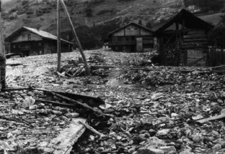
Fig.1.Damages in the village Doellach in Austria as a consequence of the Gradenbach landslide.
2.2.Fiber optic strain rosette
2.2.1.Development and installation
Absolute displacements of the landslide can be determined with the continuous GPS monitoring system and the implemented height correction models with an accuracy of less than 1 cm (Gassner et al.,2002).This accuracy is well suited to determining the long-term behavior.For the determination of local deformations,measurement systems with higher precisions and higher resolutions are required.Fiber optic sensors fulfll these requirements and are robust enough to be embedded in landslides. One successful application of fber optic measurements for the determination of the location of the boundary between stable and sliding areas of a landslide in Switzerland was reported in Iten et al. (2009).In case of the Gradenbach Observatory,the focus was placed on the early detection of an acceleration of the landslide. Therefore,a large fber optic strain(LFOS)rosette was embedded in the central landslide area to detect local compression and decompression.
The LFOS rosette is composed of three SOFO sensors with a length of 5 m.Alternatively fber Bragg grating(FBG)sensors can also be used.The SOFO sensors are based on an interferometric measurement principle.Each SOFO sensor consists of a stretched fber and a loose fber.A length change between the two anchor points of the sensor only affects the strained fber.On the contrary, a temperature change has an infuence on both fbers.Since the measurement result is the length difference of both fbers,the temperature infuence is eliminated.In our application,the sensors were separated to each other by an angle of about 120°to form a rosette in analogy to strain rosettes used in classic mechanical stress analysis(Fig.5).
The sensors were installed in 2007,parallel to the surface below the frost penetration depth at a depth of about 2 m(Fig.6).One sensor(sensor A)was oriented in the direction of movement of the landslide.More details about the development of the fber optic strain rosette can be found in Wöllner et al.(2011)and Woschitz and Brunner(2008).

Fig.2.Failure of reinforced earth structure at the road B320,Austria(Liezen Online, 2011).
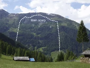
Fig.3.Deep-seated mass movement in Gradenbach landslide.
2.2.2.Results
Long-term strain measurements with the static SOFO reading unit can be performed with a precision of 2μm according to the specifcations of the manufacturer(Inaudi,2004).This was also confrmed by our own investigations(Lienhart,2005).This corresponds to a precision of strain measurements of 0.4μm/m taking into account the length of the sensors(5 m).The principal strain values ε1and ε2as well as their orientation φ can be derived from the strain measurements εA,εBand εCof the individual sensor using the following equations:


Fig.4.Monitoring installations of the Gradenbach Observatory.

Fig.5.Fiber optic strain rosette.

The LFOS measurements at the Gradenbach Observatory are usually performed automatically every 15 min from spring to autumn.In this paper,we focus on three measurement epochs where additional geodetic measurements are available.Fig.7 displays the resulting strain ellipses with respect to the reference epoch June 2007.It can be seen that almost no strain changes occurred between June 2007(epoch#1)and July 2008(epoch#2). However,a signifcant compression occurred between July 2008 and July 2009(epoch#3).
This is a typical result for the Gradenbach landslide.During the period of constant movements(2007-2008),no local strain changesoccurred.However,incaseofacceleration phases, the upper parts of the landslides are faster than the lower parts (2008-2009)and therefore local compression occurred.
2.2.3.Comparison with geodetic measurements
A local terrestrial geodetic network was established to check the results of the fber optic strain rosette for plausibility since such a LFOS rossette was installed in a landslide for the frst time.This network was measured three times(June 2007,July 2008,and July 2009)with a total station.To compare the data of the geodetic network and the fber optic strain rosette,the movements determined by the terrestrial measurements were interpolated to the end points of the strain rosette.
Fig.8 shows a comparison of the strain ellipses derived from the twodifferentmeasurementtechniques.Theprincipalstrain determined by the LFOS rossette is(-261±0.6)μm/m,and (-245±28)μm/m from the geodetic network.The difference is statistically not signifcant.However,geodetic measurements only provide a qualitative control of the fber optic measurements due to the 50 times lower precision of the geodetic measurements.
The importance of the fber optic measurements can also be seen when compared to the GPS measurements.The distance changes between the GPS points MA and MC(Fig.4)can be convertedinto strain changes.Since the orientation of the line between points MA and MC corresponds to the orientation of sensor A,the strain values can directly be compared.It can be seen in Fig.9 that the GPS measurements depict the overall trend of the strain changes,however,detailed strain analysis is impossible due to the high noise of the GPS data.This confrms that the high resolution fber optic strain measurements are crucial for depicting the early phase of a change in moving behavior of the landslide.

Fig.6.One anchor point of the fber optic strain rosette.

Fig.7.Strain ellipses derived from the fber optic strain rosette shown for three epochs (epoch#1:June 2007;epoch#2:July 2008;epoch#3:July 2009).
3.High-sensitivity monitoring of reinforced earth structures
3.1.The Longsgraben disposal site

Fig.8.Fiber optic measurements and interpolated strain ellipses derived from geodetic network.
The New Semmering Base Tunnel is a key project of the upgrade of the Austrian North-South railway connection.Prior to tunnel excavation,preparatory works had to be completed including theconstruction of the Longsgraben disposal site.This disposal site covers an area of approximately 2×10⁵m2at depths of 1.05-1.25 m above sea level.During operation of the site,the valley will be flled up to a height of 50 m.Afterwards,the site will be covered with earth and afforested.
Prior to establishing the disposal site,the small mountain stream running at the valley foor had to be relocated to a new bed at the edge of the site,up to 50 m above the current valley bottom (Fig.10).Therefore,reinforced earth structures with a length of 1.22 m were constructed on the steep valley side.
Additionally,a maintenance road was constructed with a reinforced earth ramp(Fig.11)with a maximum height of 25 m and a length of 80 m.

Fig.9.Strain changes derived from GPS and fber optic measurements.
3.2.Distributedfber optic measurement system
3.2.1.Development and installation
The reinforced earth structures were monitored during construction based on the observation method of Eurocode 7.Therefore,prism targets were mounted on the surface of the structure. The absolute movements of the prisms were measured epoch-wise twice per week with total stations.Additionally,a distributed fber optic measurement system was installed to measure the current operation grade of the geogrids within the earth structure.
Up to now,several different types of geotextiles with integrated fberopticsensing cables are available(Artiereset al.,2010;Krebber et al.,2012).However,these geotextiles were not suitable for the Longsgraben disposal site.The challenge in this application was to determine the operation grade of the specifc geogrids which were used to build the structure.Therefore,we developed a monitoring system with adapters that connect fber optic sensing cables to standard geogrids.In total 2 km of sensing cables were installed in the project area.The BRUstrain V4 from Brugg cables was selected to monitor three cross sections of the reinforced earth structure.In each cross section,up to fve geogrid levels were equipped with the sensing cables.Across section of one measurement profle is shown in Fig.12.The end point of each measurement level was directly connected to a geodetic observation point to relate the internal strain measurements to displacements measurements of the surface of the structure.The sensing cables were connected to the geogrids with adapters developed at IGMS in distances of more than 1 m.
A loop confguration with a stretched and a loose fber(Fig.12) was implemented in each measurement level.The stretched fber is sensitive to length changes between the adapters and to temperature changes,whereas the loose fber is only sensitive to temperature changes.By combining both measurement signals,the temperature infuence can be eliminated.The cables were locally protected between the adapters in order to guarantee constant strain of the stretched fber and to avoid trans-axial pressure to the cable.All sensing cables were connected to one single 2 km loop to measure all cross sections simultaneously with one distributed fber optic sensing unit.
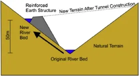
Fig.10.Relocation of the Longsgraben stream using reinforced earth structures.
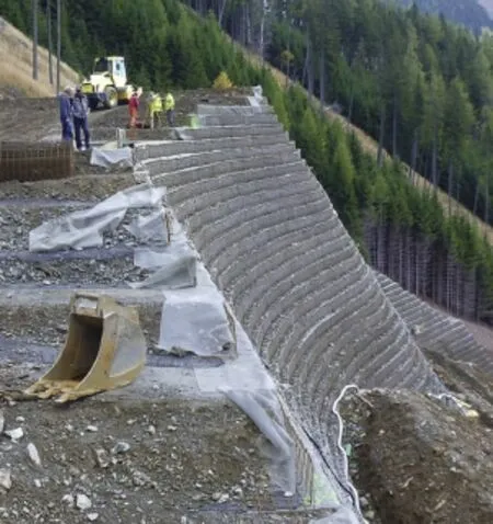
Fig.11.Construction of the reinforced earth ramp of the maintenance road.
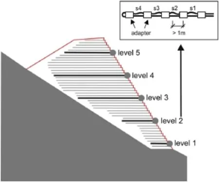
Fig.12.Monitoring levels in cross section CS2.Solid black lines:Geogrid with sensor cable;Gray dots:Geodetic prisms for conventional monitoring.
Fiberoptic measurements systemsprovide new insights into the behavior of geotechnical structures(Iten,2011),and distributedsensing is especially suited for large structures.Distributed fber optic sensing can be based on Rayleigh,Raman or Brillouin scattering(Bao and Chen,2012).Brillouin scattering occurs when light traveling in a single-mode optical fber is refected by the refractive index modulations produced by acoustic waves(Horiguchi et al., 1989).BOTDA(Brillouin optical time domain analyzer)and BOFDA(Brillouin optical frequency domain analyzer)systems use a loop confguration where one end of the fber is connected to a continuous wave pump laser and the other end to a laser which emits light pulses(BOTDA)or amplitude modulated light waves (BOFDA).In BOFDA,the light pulse is replaced by sinusoidal waves of a tunable frequency and the response to these frequencies is measured(Galindez-Jamioy and Lopez-Higuera,2012;Nöther and v.d.Mark,2012).In theory,a Fourier transform of the measurement data of a BOFDA system yields the same strain and temperature profles along the sensing fber as is measured with a BOTDA system(Nöther,2010).In our monitoring setup,a FibrisTerre BOFDA reading unit was placed into a central measurement container (Fig.13).
3.2.2.Results
The measured Brillouin frequencies along the 2 km sensing cable are shownin Fig.14.The zoomwindowdisplaysthe measured Brillouin frequencies of level 2 in cross section CS2.This level consists of four measurement segments(s1-s4,with s1 closest to the surface).Clearly visible is an increase of the strain with increasing distance from the surface of the structure.
During the construction phase,internal monitoring measurements were carried out weekly and reported to the geotechnical engineer.After the construction was fnished,the measurement interval was extended to monthly measurements.The strain development of one selected monitoring level(level 2 in cross section CS2)is shown in Fig.15.It can be seen that the strain increased up to 1%during the construction phase.As already discussed before,the strain increased with increasing distance from the surface of the structure.After the construction phase has fnished,the strain increase slowed down and stabilized.
The new internal strain measurements provided important insights into the behavior of the reinforced earth structure.The nonlinear strain distribution inside the structure cannot be detected using conventional geodetic measurements on the surface. Currently,the measurements are used to calibrate the numerical results of fnite element method of the structure.One year after installation,the fber optic monitoring system is still fully operational and will be used to monitor the internal strain development until the disposal site is completely covered with the tunnel excavation material.

Fig.13.Monitored cross sections at the Longsgraben disposal site.

Fig.14.Brillouin frequencies along the 2 km sensing cable.
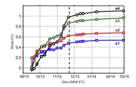
Fig.15.Strain development in level 2 of cross section CS2.
4.Conclusions
We presented two applications of high-sensitivity fber optic monitoring installations for natural and engineered slopes.The great advantage of fber optic sensors compared to traditional geodetic sensors is that the fber optic sensors can be embedded in the structure and therefore deliver deformation information at locations that are otherwise not accessible.Furthermore,in many cases deformation changes at an early stage can only be detected with fber optic sensors due to their high resolution and high precision.Conventional geodetic sensors and fber optic sensors complement each other.Geodetic sensors are well suited to depicting position changes of objects whereas fber optic sensors are better suited to determining internal strain changes.
Confict of interest
The author wishes to confrm that there are no known conficts of interest associated with this publication and there has been no signifcant fnancial support for this work that could have infuenced its outcome.
Acknowledgments
The author is grateful to the Austrian Academy of Sciences (OeAW)for funding the landslide monitoring project for several years.Additionally,I want to thank the Austrian Federal Railways (ÖBB)for the funding of the geogrid monitoring project,especially the participating departments of ÖBB-Infrastruktur AG:Tunneling, Surveying and Data Management,Research and Development.
Artieres O,Beck YL,Khan AA,Fry JJ,Courivaud JR,Guidoux C,Pinettes P.Assessment of dams and dikes behavior with a fbre optic based monitoring solution.In: Garcia RR,Mir MA,Bitrian FH,Dios RL,Caballero MRC,editors.Dam Maintenance and Rehabilitation II,Proceedings of the 2nd International Congress on Dam Maintenance and Rehabilitation.Leiden:CRC Press/A.A.Balkema;2010.p.8.
Bao X,Chen L.Recent progress in distributed fber optic sensors.Sensors 2012;12(7):8601-39.
Brückl E,Brunner FK,Kraus K.Kinematics of a deep-seated landslide derived from photogrammetric,GPS and geophysical data.Engineering Geology 2006;88(3-4):149-59.
Brückl E,Brunner FK,Lang E,Mertl S,Müller M,Stary U.The Gradenbach Observatory-monitoring non-stationary deep-seated gravitational creep by geodetic, hydrological,and seismological methods.Landslides 2013;10(6):815-29.
Galindez-Jamioy CA,Lopez-Higuera JM.Brillouin distributed fber sensors:an overview and applications.Journal of Sensors 2012.http://dx.doi.org/10.1155/ 2012/204121.Article ID 204121.
Gassner G,Wieser A,Brunner FK.GPS software development for monitoring of landslides.In:Proceedings of FIG XXII Congress Washington,D.C.,USA;2002 [CD-ROM].
Horiguchi T,Kurashima T,Tateda M.Tensile strain dependence of Brillouin frequency shift in silica optical fbers.IEEE Photonics TechnologyLetters 1989;1(5):107-8.
Inaudi D.Testing performance and reliability of fber optic sensing system for longterm monitoring.In:Proceedings of SPIE Volume 5502,the 2nd European Workshop on Optical Fibre Sensors.Spain:Santander;2004.p.552-5.http:// dx.doi.org/10.1117/12.566713.
Iten M.Novel applications of distributed fber-optic sensing in geotechnical engineering.PhD Thesis.Zürich,Switzerland:ETH Zürich;2011.
Iten M,Schmid A,Hauswirth D,Puzrin AM.Defning and monitoring of landslide boundaries using fber optic systems.In:Prediction and Simulation Methods for Geohazard Mitigation:Proceedings of the International Symposium on Prediction and Simulation Methods for Geohazard Mitigation(IS-Kyoto2009). Kyoto,Japan:CRC Press;2009.p.451-6.
Krebber K,Lenke P,Liehr S,Nöther N,Wendt M,Wosniok A.Structural health monitoring by distributed fber optic sensors embedded into technical textiles. In:Proceedings of SPIE,the International Society for Optical Engineering;2012. http://dx.doi.org/10.1117/12.868052.
Lienhart W.Experimental investigation of the performance of the SOFO measurement system.In:Structural Health Monitoring 2005,Proceedings of the 5th International Workshop on Structural Health Monitoring.Stanford,USA:DES-tech Publications,Inc.;2005.p.1131-8.
Nöther N.Distributed fber sensors in river embankments:advancing and implementing the Brillouin optical frequency domain analysis.BAM Dissertations 64. Berlin:BAM Bundesanstalt für Materialforschung und-prüfung;2010.
Nöther N,v.d.Mark S.Displacement and settlement monitoring in large geotechnical structures with novel approach to distributed Brillouin sensing.In:Proc. Civil Structural Health Monitoring Workshop(CSHM-4),Berlin,Germany;2012. Online Liezen.Hangrutschung in Schladming.2011.www.blo24.at/nachrichten/ aktuelles-aus-dem-bezirk/item/936-hangrutschung-in-schladming.
Wöllner J,Woschitz H,Brunner FK.Testing a large fber optic strain-rosette, embedded in a landslide area.In:Proc.8th Int.Symp.Field Measurements in GeoMechanics(FMGM-8),Berlin,Germany;2011.
Woschitz H,Brunner FK.Monitoring a deep-seated mass movement using a large strain rosette.In:Proceedings of the 13th FIG Symposium on Deformation Measurements and Analysis,Lisbon,Portugal;2008.

Werner Lienhartreceived his MS degree in Surveying from Graz University of Technology in 2001.Following his studies he was university assistant for fve years at the Institute of Engineering Geodesy and Measurement Systems at Graz University of Technology.At this position he was involved in various monitoring projects including internal and external sensors.In 2006 he received his Ph.D. degree in Surveying from Graz University of Technology.In the same year he joined the product management group at Leica Geosystems at the headquarter in Switzerland.At Leica he was responsible for the development of the Galileo and GPS L5 capable receivers and the Leica imaging total stations.His current position is Head of the Institute of Engineering Geodesy and Measurement System at Graz University of Technology.The institute has a renowned measurement laboratory for the calibration of geodetic measurement devices.His main research interests are geodetic and fber optic sensors and the analysis of structural monitoring data.He is member of several scientifc commisttees like the Austrian Geodetic Commission,the Society for the Calibration of Geodetic Devices(GKGM)and council member of the International Society for Structural Health Monitoring(ISHMII).
*Tel.:+43 3168736321.
E-mail address:werner.lienhart@tugraz.at.
Peer review under responsibility of Institute of Rock and Soil Mechanics,Chinese Academy of Sciences.
1674-7755©2015 Institute of Rock and Soil Mechanics,Chinese Academy of Sciences.Production and hosting by Elsevier B.V.All rights reserved.
http://dx.doi.org/10.1016/j.jrmge.2015.04.002
 Journal of Rock Mechanics and Geotechnical Engineering2015年4期
- Journal of Rock Mechanics and Geotechnical Engineering的其它文章
- A theoretical derivation of the Hoek-Brown failure criterion for rock materials
- Strength properties of soft clay treated with mixture of nano-SiO2and recycled polyester fber
- Key technologies of drilling process with raise boring method
- Analysis of horizontal displacement distribution caused by single advancing longwall panel excavation
- Susceptibility assessment of debris fows using the analytic hierarchy process method-A case study in Subao river valley,China
- Optimal design of anchor cables for slope reinforcement based on stress and displacement felds
