Field investigations of high stress soft surrounding rocks and deformation control
Weijin Yu,Weijun Wng,Xinyun Chen,Shohu Du
aHunan Provincial Key Laboratory of Safe Mining Techniques of Coal Mines,Hunan University of Science and Technology,Xiangtan,Hunan 411201,China
bSchool of Energy and Safety Engineering,Hunan University of Science and Technology,Xiangtan,Hunan 411201,China
Field investigations of high stress soft surrounding rocks and deformation control
Weijian Yua,b,*,Weijun Wanga,Xinyuan Chenb,Shaohua Dub
aHunan Provincial Key Laboratory of Safe Mining Techniques of Coal Mines,Hunan University of Science and Technology,Xiangtan,Hunan 411201,China
bSchool of Energy and Safety Engineering,Hunan University of Science and Technology,Xiangtan,Hunan 411201,China
A R T I C L E I N F O
Article history:
Received 5 August 2014
Received in revised form
16 March 2015
Accepted 30 March 2015
Available online 4 June 2015
High stress
Soft surrounding rocks
Roadway deformation
Field investigation
Control technology
Field investigations of high stress soft rock deformations show that the high stress soft rock roadway can slide with large deformation.Severe extrusion and foor heave can also be subsequently observed.The supported roadway can be locally damaged or completely fail,where the foor has a large deformation and/or is seriously damaged.The factors inducing large deformation of surrounding rocks in deep roadway are rock strengths,structure face cutting types,stress states,stress release,support patterns, and construction methods.Based on the deformation characteristics of high stress soft rock roadway,a comprehensive support scheme is proposed.The overall support technology of“step-by-step and joint, hierarchical reinforcement”for roadway is presented,and the anchor cable and bolt parameters to check the design methods are also given.Finally,the proposed comprehensive support method“bolt+metal mesh+U-steel arch+shortcrete+grouting and cable”is used in the extension section of east main haulage roadway at-850 m level of Qujiang coal mine.The 173-day monitoring results show that the average convergence of sidewalls reaches 208 mm,and the average relative convergence of roof and foor reaches 448 mm,suggesting that this kind of support technology for controlling large deformation of high stress soft surrounding rock roadway is effective.
©2015 Institute of Rock and Soil Mechanics,Chinese Academy of Sciences.Production and hosting by Elsevier B.V.All rights reserved.
1.Introduction
Under high in-situ stress,the soft surrounding rocks are basically characterized by great deformation rate,large and long-term deformation.At present,the deformation control technology of soft surrounding rocks in high in-situ stress environments is a hot and challenging issue.With respect to deformation mechanism, Chen et al.(2011)used the Lagrange multiplier method to model large deformation and nonlinear frictional contact of excavation boundary in a deep soft rock tunnel.The deformation of the transportation tunnel was asymmetrical due to the inclination of rock strata.The procedures for design of supports and stabilization measures in roadways were described byˇSˇnupárek and Koneˇcný (2010).He et al.(2007)summarized the causes of supporting failure of deep soft rock roadway as follows:low strength of wall rock, inadequate support,water effect,and structure stress effect.Kanji (2014)discussed the efforts made to investigate soft rocks,and stated that soft rocks have intermediate strength between soils and hard rocks.Gonzalez-Nicieza et al.(2008)adopted a numerical method to analyze convergence and constraint procedure for different section shapes and overburden depths.Hayano et al. (1999)suggested that the most typical characteristic of deep soft rocks is the long-term creep behavior,and discussed it through the observations of laboratory experiment.Bai et al.(2007)used the exponential creep model to analyze the changing behavior of stress and deformation rate of surrounding rocks with elapsed time,the effects of secondary supporting time and the intensity of surrounding rocks on deformation.With respect to the control of concentrated stress in surrounding rocks and reduction of rock crushing area,Wang et al.(2011)argued that the main reason of severe deformation is due to the active pressure and low intensity of the original support.Verma and Singh(2010)discussed the stability of tunnel and stress pattern,and performed numerical analyses for stress-strain distribution of tunnel excavation and associated support systems.
As for the control measures,Wang et al.(2011)proposed a supporting technology of fexible layer with rigid gap(He et al., 2005),the large deformation coupling support(He et al.,2013) and the anchor bolt with constant resistance and large deformation.The comprehensive support method of“bolt+metal meshes+pouring cover+anchor+grouting+foor anchor”was selected to rework the main roadway(Yu et al.,2014),based on theoverlap arch bearing body strength theory for deep soft surrounding rocks(Yu et al.,2010).In addition,large deformation control of soft surrounding rocks of roadway with high stress and stability of support structure are important issues associated with increasing support strength(Xie et al.,2010).
The cases studied are mainly concerning deep rock mass deformation characteristics,for which reasonable control measures are proposed.However,due to complex geological conditions and lithology differences,the deformation characteristics of surrounding rocks in deep mining are not fully understood,which sometimesmakesthedesignofcontrolmeasuresandsupport parameters impractical,resulting in serious deformation and/or failure.In this regard,we examine several typical haulage ways of deep mines in Jinchuan,Qujiang and Pingdingshan with respect to failure modes based on site investigations.The investigations include rock strength,structure face cutting type,stress state, support pattern,construction method,and other factors that have impacts on deep roadway stability to provide real data for roadway support design and control measures adopted.
2.Roadway failure modes
The details of typical deep mines in Jinchuan,Qujiang,and Pingdingshan are shown in Table 1.
Soft rocks under high in-situ stress can lead to overall instability of surrounding rocks.The soft rock deformation characteristics under high in-situ stress can be summarized as follows:
(1)The two sidewalls of tunnel were severely squeezed under high in-situ stress,triggering large deformation of the two sidewalls and even cracking.The failure was mainly induced by large horizontal and lateral pressures.Longitudinal fssures were observed at two sidewalls,and their length basically exceeded the convergence value of 50 mm,whilst the sidewalls deformed inward and the roadway vault was damaged or crushed.The supporting arch deformed upward,thus a peach-shapedorpointedarchundershearingcanbe observed.If the two sidewalls deform signifcantly and ultimately spalling occurs,a cavity can be formed between the shotcrete and surrounding rocks.In this case,installed wire mesh can be twisted along with any kind of spray anchor network.The U-steel yieldable arch can also be bent or broken. Ultimately,the spray layer was broken into pieces,and the surrounding rocks were extruded as shown in Fig.1a and b.
In addition,because rock mass loosening occurred on the two sidewalls,serious collapse at the bottom of roadwaycould be observed.In the Qujiang coal mine,the collapse in the zone from the upper to the corner of roadways was also serious. Sometimes the entire sidewall of roadway showed strong caving as illustrated in Fig.1c and d.When serious collapse occurred,a cavity was formed between local anchor support structure and surrounding rocks.In a form of twisting,the steel bars strongly twisted in association with large deformation.Based on feld monitoring and observations,the fnal deformation of the two sidewalls of roadways was approximately 350-520 mm after one month of completion.
(2)Most roadway roofs failed with large deformation.Under high in-situ stress,when the roadway roof experienced a large deformation due to overburden stress,bolts,shotcrete,concrete lining,U-steel,and scaffolding tended to yield,causing local or global failure and/or damage.In addition,due to horizontal stress,roadway vault also experienced a large upward displacement.The roadway could not adapt to this large deformation and thus failed,as shown in Fig.2.
(3)The foor and bottom corners of roadway were damaged by strong foor heave.Under high in-situ stress,large deformation of surrounding rocks induced by the foor heave can be observed in concrete-uncovered or inverted arch-missing regions.The deformation in these regions is larger than 500 mm or even up to 1000 mm.The larger deformation of surrounding rocks can result in severe uneven deformation of the two sidewalls of the roadway,represented by violent destruction of concrete foor rising from the middle or corners.However,in the roadway with back cover and/or inverted arch,the roadwayfoor corner will also undergo large deformation under high insitu stress,leading to bending failure of the whole roadway as shown in Fig.3.

Table 1Basic information of investigated mines.

Fig.1.Deformations of sidewalls of a roadway.
3.Failure mechanism analyses of deep roadway
3.1.Effect of soft rock on roadway deformation
The soft rock concept has been proposed and discussed in many studies,e.g.He(2014)and Kanji(2014).Soft rocks have low to extremely low strength,which basically contain clayey minerals of kaolinite,montmorillonite,and illite.Soft rocks under low stress level(e.g.uniaxial compressive stress of 15 MPa)can experience signifcantly large deformation.Soft rock can thus be regarded as low strength engineered rock,in which the argillaceous rocks are the main component,and the clay minerals can slip and expand under high stresses.Second,due to weak structural face development in rocks,such as small-size faults,interlayer shear surface, bedding plane and joint fssure,rock strength can be signifcantly reduced.In addition,structural surfaces are usually covered with claylayer,and thus under the action of groundwater,the material of interface will experience softening or argillization,resulting in instability or failure of rock mass.In presence of structural surface, the surrounding rock can be classifed as bedded cataclastic structure,cataclastic structure,loose structure,and broken structure(Cai et al.,2013).
The soft rock has the characteristics of plasticity,swelling, disintegration,dispersion,rheology,thixotropy and ion exchange. Unloading effects due to excavation on the rock mass will change the stress state of the surrounding rocks,from three-dimensional (3D)to two-dimensional(2D)because of the release of a directional stress.In order to illustrate the infuence of surrounding rocks on roadway stability,some investigations and deformation monitoring of deep roadway in each mining area were carried out, and the cross monitoring method with the vertical line and the laser range instrument was used.The deformation curves and deformation rate curves fordifferent lithologyconditions at a depthof 900 m are shown in Figs.4 and 5.According to the monitoring results,some conclusions can be drawn as follows:

Fig.2.Deformation of roadway roof.
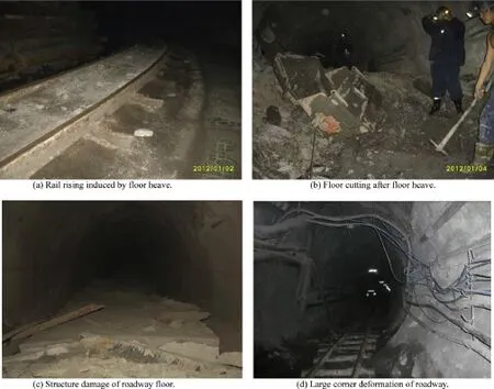
Fig.3.Deformations of roadway foor.

Fig.4.Roadway deformation curves of argillaceous rock mass.
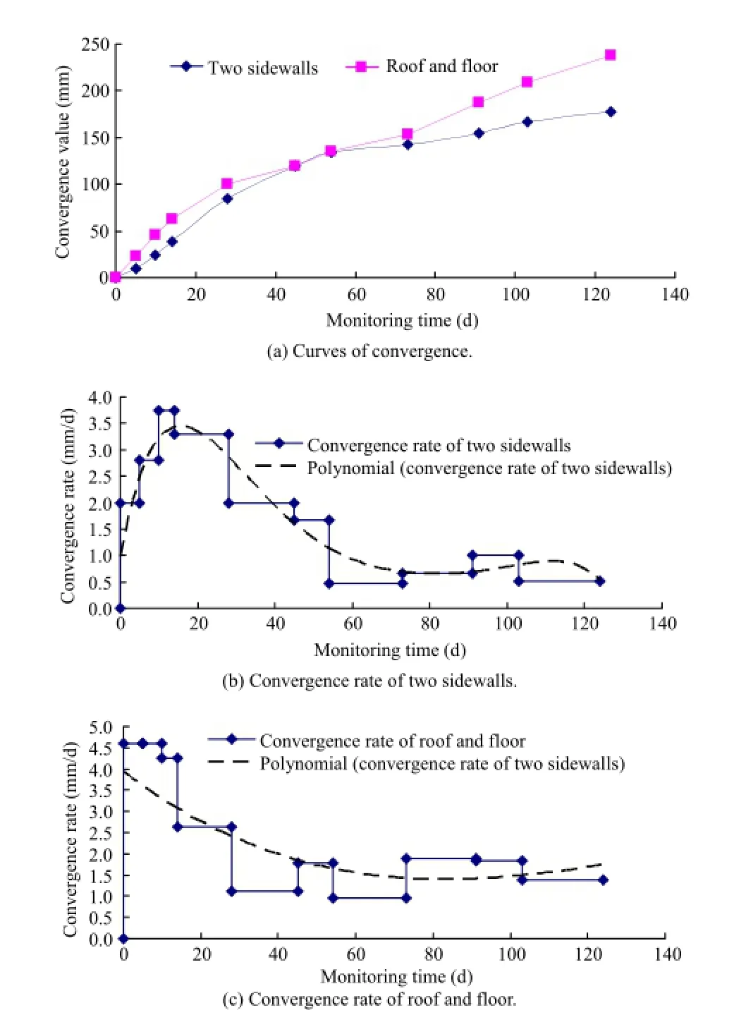
Fig.5.Roadway deformation curves of arenaceous rock mass.
(1)For rocks with low strength(e.g.argillaceous rock),under the conditions of high stress,the deformation was signifcantly large at two sidewalls,roof and foor.Fig.4 shows that under the action of high stress,the convergence of two sidewalls reached 1102 mm after 183 days,and that of roof and foor reached 766 mm.After that,the deformation rate was larger than 3 mm/d,and was still unstable at deformation stage.
(2)For rocks with high strength(e.g.arenaceous rock)under high stress,the deformation was signifcantly smaller than that with low strength.It can be seen in Fig.5 that under the action of high stress,sidewalls convergence reached 178 mm after 124 days,while roof and foor convergence reached 239 mm.After that,the deformation rate was less than 1.5 mm/d,and was stable at deformation stage.
3.2.Effects of cutting type and weak interlayer on roadway deformation
3.2.1.Effects of thin layered rock on roadway deformation
There are basically three kinds of thin layered rocks for mine roadway:horizontal,oblique,and vertical(Fig.6).In general,when the horizontal stress acts on the layered rock mass,it is very easy to slidebecauseofweakbondingforcebetweenlayers.For surrounding rocks in deep roadway,due to the large horizontal stress,layered rock will slip to the roadway space when the directions of the layered rock mass and the horizontal stress are similar.In this case,the sidewalls of roadway heaved as shown in Fig.6a.When the angle between the layered rock mass and the horizontal stress is relatively large,the upper thin layered rock mass on one sidewall will slip more than the lower rock mass, which is induced by the horizontal stress as displayed in Fig.6b. When the horizontal stress acts in the direction normal to the layered rock mass,the stress state of surrounding rocks is roughly uniform associated with the smallest deformation.However,under high stress conditions,soft rock roadway may present the deformation characteristics as shown in Fig.6c.
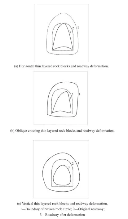
Fig.6.Failure modes of roadway in thin layered rock mass.

Fig.7.Existing modes of rock block and failure modes of roadway.
3.2.2.Relationship between rock block and deformation of roadway
Each block cut by joints has a major effect on roadway stability, especially the rock blocks located on the top of roadway as shown in Fig.7a.Therockmassseparatedfrombedrockwillposedirectlystress on support structure through gravity.If support strength is weak, rock block falls and free space on the top of roadway occurs.The upper rock on sidewalls of roadway also has a signifcant effect on roadway stability,which is easy to be separated from the bedrock to producemassiverock.Inthisregard,upperlooseblocksareformedin roadway and are free to side in a form of big blocks.It can be noted that the loose region is considerably large as shown in Fig.7b.
When the block rock is separated from bedrock,the roadway surface will be signifcantly uneven.Small contact area between surrounding rocks and support structure can be observed and stress concentration will be induced consequently under high stress.In this instance,it is most likely to destroy the support structure and the roadway.
3.2.3.Relationship between loose fractured rock mass and deformation of roadway
In the structurally damaged zone of engineered rocks,typical expansion will be triggered under high stress.The surrounding rocks associated with joints and fssures will gradually expandunder the combining actions of tensional,compressive and shear stresses,and thus the joints are dislocated with large displacement. The increase of rock volume induced by rock block rotation and joint expansion are termed as deformation.The fragmentation and expansion of surrounding rocks can lead to excessive deformation or failure of roadway which is categorized as the key block failure around roadway,side shearing failure,combination failure,etc.
In addition,loose fractured rock mass can easily collapse under the action of high stress through stress release.As for the loose rock mass with large porosity,adhesive force among the particles is very low.Afterexcavation of roadway,the surrounding rocks wouldbreak very quickly,and form a collapse circle after expanding.Roadway excavation in the original rock mass can break the existing 3D stress stateofsurroundingrocks,andthestressisredistributedbyreducing radial stress to zero,increasing shear stress and generating stress concentration,untilanewequilibriumof3Dstressstateisreached.In this regard,the stress state of surrounding rocks is changed,and the soft rock strength is signifcantly reduced.Due to its very low strength,rock fails when the concentrated stress is greater than the strength of surrounding rocks,thus the damaged zone extends from theperipherytothedeepfracturedzone,whichcanbecalledcollapse circle of surrounding rocks.Field observations show that the surrounding rocks of roadway have a widespread collapse circle due to excavation-induced stress distribution,which can be also calibrated throughlaboratorysimulationtests.Largecollapsecirclemeansgreat convergence,andthereforeitismorediffculttosupporttheroadway after excavation.Generally,the collapse circle is the natural characteristic of soft rock roadway.The thickness of collapse circle of surrounding rocks is the function of stress and strength of surrounding rocks,refecting the diffculty in rock supporting.
Moreover,for the low strength surrounding rocks,large plastic deformation can be induced under a certain small stress,and it will undergo continuously increasing plastic deformation.The large plastic deformation can result in height reduction of roadway, extrusion of two sidewalls,cross-sectional reduction,etc.It is rather diffcult to use low strength supports for the synchronous deformation of surrounding rocks and supports,and therefore large deformationandfailureofroadwaycannotalwaysbeeffectivelycontrolled. In this instance,large loose region and large granular pressure of surrounding rocks lead to damage of roadway.When using highstrength supports,the ground pressure imposed on supports would increase with increasing deformation.If the pressure exceeds the limit of support strength,deformation-induced damage to supports wouldoccur.Accordingtotheanalysesofavarietyofroadways,itcan benoted that inloose surrounding rocks of roadways,roof damage is caused by dispersed ground pressure,and the damage of sidewalls is caused by shear deformation.After that,the roof falls even if highperformance concrete structures are employed for roadway support due to signifcantly high shear stress in sidewalls,and a large-scale shear failure would occur in the support structures.
3.2.4.Relationship between weak interlayer and roadway damage
If weak interlayer goes through the roadway as shown in Fig.8, shear stress concentration can be generated under high stress, which can lead to larger shear stressthan the limit shear strength of structural planes.Thus rock mass structure would slip along the structural planes,and rock mass fails.In particular,soft interlayer would extrude outward under high geo-stress,resulting in local failure or damage of roadway.
3.3.Relationship between geo-stress release and roadway deformation
Another key factor that can induce large deformation of roadway is the presence of geo-stress.Before excavation of rocks, the geo-stress is in a 3D compression.After excavation,the rocks have a free face,suggesting that the 3D stresses are changed to 2D stresses in association with stress release close to roadway surface. In this case,tensile and shear stresses are generated,which can produce large deformation of surrounding rock or roadway damage.
In order to analyze the relationship between geo-stress release mode and roadway deformation,investigations are made on deephigh stress deep roadway,which can be roughly described as follows:
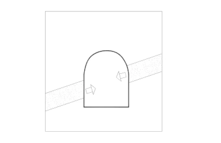
Fig.8.Soft weak interlayer through the roadway.
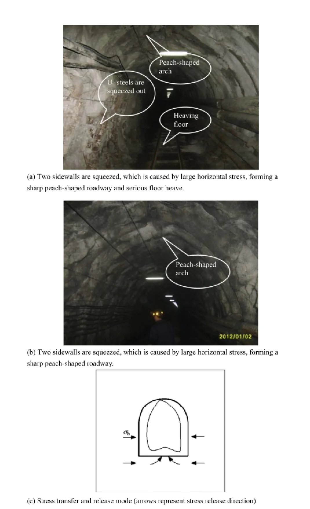
Fig.9.The actual deformation and stress release mode caused by large horizontal stress.
(1)Sidewalls of roadway are squeezed by large horizontal stresses, and a sharp peach-shaped roadway can be formed.If the foor support strength is insuffciently high,stress can be released from the foor,and serious foor heave can be induced subsequently as shown in Fig.9.The stress redistribution and roadway damage modes are mainly induced by large horizontal stress imposed on two sidewalls,resulting in serious extrusion of sidewalls,and thus a sharp peach-shaped roadway is formed.
(2)Roadway roof subsidence is caused by large vertical stress;at the same time,stress is transferredtosidewalls and foor.In this case,the stressis released gradually,but the global convergence of roof and foor increases as shown in Fig.10.Due to the large vertical stress acting on the roof,the roof deforms signifcantly and subsidence is induced subsequently.In addition,the bottom of the roadway is weakly supported,therefore high stress is released and transferred to sidewalls and foor,suggesting that the foor and sidewalls will deform or extrude more or less.
(3)Although minor difference may exist between vertical and horizontal stresses,the whole section will also deform under high in-situ stress(>20 MPa).In this condition,stress is basically released to the excavation space as it continuously acts on support structure.The support structure and surrounding rocks deform towards the excavation space,thus some smaller fullsection roadways are formed.The deformation and stress release are shown in Fig.11.
(4)When the maximum principal stress intersects with the roadway at a specifc angle as shown in Fig.12,the deformation matches the maximum stress direction.If the section of roadway is symmetric,the stress release is also symmetric, causing substantive foor heave when the stresses are transferred to the foor.
3.4.Relationship between roadway deformation and support patterns
Bolting-mesh-spray,cable,U-steel,grouting and other supporting patterns are commonly used for surrounding rocks in high stressroadway.However,it is impossible to solve largedeformation problem using a single pattern,where the combining support patterns are needed in order to achieve more desirable results.But in actual operation,one support pattern or combining patterns is frequently reported due to various reasons,e.g.lack of construction cost,or the rocks are not supported timely.According to feld investigation and related information analysis,different support patterns of roadway in comparison of deformation of surroundingrocks with different characteristics(see Fig.13)can be specifed as follows:

Fig.10.The actual deformation and stress release mode caused by large vertical stress.

Fig.11.The actual deformation and stress release mode when the vertical stress is approximately equal to the horizontal stress.
(1)When the support pattern of“bolt+wire mesh”is employed for roadway under high stress,the surrounding rocks quickly produce dilitancy after excavation,and thus large deformation can be induced.Various cracks can also be observed in roadway. Although the“bolt+wire mesh”support pattern is adopted, exposed rocks can be easily weathered or deteriorated because of lack of full-section support of the surrounding rocks.In the roadway containing clay minerals,rock argillization,hydration and swelling can be produced if water is encountered,resulting in side foor heave and roof subsidence.In addition,the support type of roadway can also result in crack extension in soft rock, separated sidewalls,and roofseparation.It should be noted that for the“bolt+wire mesh”support,the deformation of surrounding rocks increases linearly till failure,as shown in Fig.14a.
Therefore,for the support pattern of“bolt+wire mesh”under high stress,the surrounding rocks deform very quickly after roadway excavation in a very short period of time.This support pattern is suitable for temporary support of roadway, but if the secondary support is not carried out in time,surrounding rocks will deform rapidly under the action of high stress till failure of roadway as shown in Fig.14a.
(2)The support pattern of“bolt+wire mesh+shotcrete”is better than the“bolt+metal mesh”support pattern after full-section support(closure)of surrounding rocks is properly considered. In the initial monitoring period,the deformation rate was small;but the loose circle expanded rapidly with the increasing surrounding rock deformation when only bolt support was used.In the later stage,the deformation was in an acceleration stage,resulting in large deformation and instability of roadway. The deformation of roadway is shown in Fig.14b.
Generally,roadways using this kind of support pattern are mainly damaged at sidewalls at the beginning.As the damage of sidewalls increases,shotcrete can be separated fromroadway surface and its support capability can then be lost.Therefore, the deformation of roadway develops rapidly,and thus rock squeezing,roof subsidence and foor heave occur as shown in Fig.14b.
(3)Whenthecombiningsupportpatternof“bolt+wire mesh+shotcrete”(the frst support)and“anchor”(the secondary support)is adopted,the surrounding rocks will remain relativelystable.Evidently,the frst support system(bolt+wire mesh+shotcrete)plays a major role in formulating a temporary support,improving initial bearing capacity of the surrounding rocks so as to maintain the integrity of surrounding rocks.In addition,the secondarysupport(anchor)plays a major role in the permanent support of load-bearing arch structure so as to form a stable structure.Therefore,this support system makes the surrounding rocks more stable,maintaining a constant deformation rate(Fig.14c).However,due to the high stress state,the deformation would increase with elapsed time, and the anchor or bolt is ultimately broken or cut as shown in Fig.14c.

Fig.12.The actual deformation and stress release modes when the vertical stress has a certain angle with the horizontal stress.

Fig.13.Roadway deformation regulations of different support patterns.
(4)When the support pattern of“bolt+wire mesh+U-steel+shotcrete”is adopted,the objective is frst to allow rock deformationandthento reducerockdeformation.The“bolt+wire mesh”support is fexible,but the U-steel frame support is rigid.They are integrated to combine“soft”bolt and“rigid”support.Initially,interaction between surrounding rocks and U-steel is weak,and the deformation rate is high. When the deformation increases to a certainvalue,the pressure of U-steel imposed on surrounding rocks starts to increase and grows larger with increasing deformation to resist the deformation of the surrounding rocks,signifcantly reducing the deformation rate.However,the U-steel would yield with the increasing deformation if it could not resist the pressure applied by the surrounding rocks.This can result in gradual increase of the deformation rate of the surrounding rocks and eventually lead to instability.The actual deformation of roadway with this support is shown in Fig.14d.
(5)When the support pattern of“bolt+wire mesh+shotcrete”and“grouting”reinforcement is adopted,the grouting can play a major role in support.The grouting can fll the fractures of jointed rock mass and improve the integrity and strength of the surrounding rocks.Thus groutingin associationwith wiremesh can greatly improve the self-bearing capacity of surrounding rocks.For simplicity,surrounding rocks with the support pattern of this type can remain relatively stable,as shown in Fig.14e.However,if the surrounding rocks have characteristic of strong rheology,rock deformation will increase under the action of high stress;therefore the roadway can also produce large deformation until instability(Fig.14e).In addition,the sidewalls,roof and foor can undergo serious deformations when the horizontal stress is high.

Fig.14.Roadway damage characteristics of different supporting forms.
3.5.Infuence of excavation disturbance on roadway deformation
In mining engineering,underground excavations are complex due to many roadways and chambers close to each other.Thus mining excavation would have an important infuence on the stability of surrounding rocks.When blasting is employed,the blasting-induced stresscan havedamagestothe surrounding rocks, leading to the instability of roadway and chambers.
The monitoring curves of haulage roadway and rail roadway before and after excavation in Qujiang coal mine with a mining depth of 886 m are studied,respectively.Two roadways have a parallel spacing of about 20 m,and the haulage roadway is 100 m ahead of rail roadway.The host rock consists of mudstone and silty, black grayish,and thin to medium-thick bedding rocks.The joints arewell developed with lowstrength.The drill-and-blast method is used for full-section excavation.
The infuence of excavation disturbance on roadway deformation can be summarized as follows:
(1)The drill-and-blasted roadways with a parallel spacing of 20 m have a signifcantly large impact on pre-existing roadway with a range of around 10-20 m from the heading face center.The impact is characterized by larger displacement and greater deformation rate than other roadways.In this period of time, the distance of the drill-and-blasted roadways with a parallel spacing of 20 m is just about 15 m from the heading face center.
(2)The largest disturbance during roadway excavation happens at a distance approximately25 m awayfromtheworking face.The displacement rate is generally greater than 4 mm/d,and is signifcantly reduced when the advancing is away from the monitoring point.In addition,excavation disturbance to drilland-blasted roadways is higher than that to adjacent roadways.
(3)It is well known that when the two roadways are excavated in close proximity,the excavation-induced disturbance is clearly evident.According to feld surveys,when the spacing of roadways is within 30 m(dependent on blasting scale and rock strength),excavation-induced disturbance is large.Deformation of roadway at different distances from the working face is shown in Fig.15.Excavation zones can be divided into the following ones:excavation damaged zone,major infuence zone,minor infuence zone,and non-disturbance zone.Thus it can be noted that the excavation damaged and disturbed zones are basically within 30 m from the excavating face.
(4)Roadway deformation and failure induced by excavation basicallyhave the samecharacteristicstoa certaindegreeaccording to feld observation.When excavated roadways are adjacent and parallel to pre-existing roadways at nearly the same elevation,one sidewall or arch of roadway will deform,or rock slabbing or spalling will occur.
4.Support guidelines and control measures of large deformation roadways under high stress
4.1.Support guidelines of roadway
According to roadway damage states and related theories, support guidelines of roadway under high stress can be listed as follows:
(1)The primary support stiffness and strength should be signifcantly improved.This can effectively control the increasing deformation of surrounding rocks,which includes two parts. The frst one is the slide along structural surface,crack opening and expansion,which belong to discontinuous deformation. The second is the elastoplastic deformation of rocks before the peak strength is reached,including the global deformation of anchorage zone,which belongs to the continuous deformation. Because of lowstrength of structural plane,reasonable roadway supporting pattern can be considered as follows:
(i)The initial stiffness and strength of support system are greatlyimprovedtoeffectivelycontroldiscontinuous deformation of surrounding rocks.In this regard,the integrity of surrounding rocks can be roughly maintained.
(ii)Support system should use suitable technologies,allowing continuous large deformation of surrounding rocks to release high stress.
Compared with traditional support concept of“frst using fexible and then rigid”support system,i.e.frst to allow and then restrain rock deformation,the support concept in deep and complex roadways is rather different. We should use the principle of“frst rigid,then gentle,and fnally rigid”.The concept can be interpreted that support system should frst provide resistance,and then allow rock deformation to a certain degree,and fnally limit rock deformation in order to maintain the integrity of surrounding rocks and keep the strength of surrounding rocks as possible.
(2)The support stiffness should be improved to form high bearing capacityof prestressed structure at the earliest.Prestressed bolt support mainly plays a role in controlling sliding and moving of surrounding rocks of anchorage zone and reducing crack initiation and propagation.In this instance,the surrounding rocks are in a state of compression to reduce tensile-and-shear failure and bending deformation of rocks.The prestressed bearing structure of high rigidity should be kept in the anchorage zone in order to prevent separation of layers outside the anchorage zone and to improve stress distribution in deep rocks.
(3)The bolt plate,steel belt and wire mesh can be employed to increase prestressed area and to support surrounding rocks. According to site-specifc conditions of roadway,the key of the support design is to obtain an effective prestress loss when determining reasonable scheme.The scope of one single bolt prestress is very limited,thus the plate,steel belt and wire mesh can be used to transfer stress to far-feld surrounding rocks.For the roadway surface,even a small magnitude of support force can signifcantly keep the integrity of the roofand-rock structure and reduce the deformation of surrounding rocks.
(4)Engineers should adopt the support pattern of“bolt and cable”in association with high prestress,high strength and high stiffness,to effectively control rock deformation and failure and toavoidsecondarysupportorunexpectedroadway maintenance.
(5)If necessary,grouting can be used to improve the strength and integrity of broken rock mass so as to keep the integrity of loose zone.

Fig.15.Roadway deformation curve at different distances from working face.
4.2.Control measures
Based on the above analyses,the core idea of this kind of roadway support is to improve internal rock strength as possible, and prevent concentrated stress of surrounding rocks transferring to other zones.The overall support technology of roadway can thus be determined by strengthening the support system incrementally. Therefore,according to the deformation characteristics of surrounding rocks,a comprehensive support method of“bolt+wire mesh+U-steel arch bracket+shotcrete+grouting and cable”can be used for the whole section.
The following scheme can be applied according to site-specifc conditions in different roadways,thus the parameters and construction method will also differ:
(1)Primary support:bolt,wire mesh,U-steel arch bracket,shotcrete,and ladder beam.
(2)Secondary support:two-step grouting,anchor and cable beam with leg lock.
(3)Integrated technology of foor reinforcement:lock legs in middle position of each U-steel frame by using lap type cable, and the U-steel bracket tomaintain the integration of thewhole roadway section.
5.Case studies
Taking the-850 m level roadway in Qujiang mine for example, the main haulage roadway extends to a new excavation section, which is mainly composed of weathered layer of siltstone.The lithology of soft rocks is black,thin to medium-thick beddingassociated with thinmudstone and fne sandstonebelt.Itcontains a small amount of siderite concretions,and joints are well developed. From the monitored deformation data of pre-existing roadways,it is known that large deformation of surrounding rocks could last for a long time.Thus the roadwaywas repaired for many times,and the maintenance work was very large.The support and repair cost reached more than 20,000 RMB/m.In order toaddress the problem, a new support scheme should be considered for these roadways,i.e. a comprehensive support method of“bolt+wire mesh+U-steel arch bracket+shotcrete+grouting”+“cable”.
(1)Bolt support parameters
Thread bar bolt without longitudinal rib ofthe size of φ22 mm×2200 mm associated with BHRB500 rebar without longitudinal rib was used for this project.Three K2350 resin anchoring agents were used for each bolt with anchoring force not less than 70 kN.The spacing was 700 mm×700 mm as shown in Fig.16a.Full-section was considered with wire mesh and steel ladder beam.The wire mesh has a diameter of 6 mm and the spacing of 100 mm×100 mm,which was determined according to specifcations for the wire mesh of the size of 1000 mm×800 mm. Wire mesh junction must be bolted,and each neighboring lap length is no less than 100 mm.The steel ladder beam was welded by round steel with the diameter of 12 mm.
(2)U-steel bracket
U29 type steel bracket was employed in this project with the spacing of 700 mm.The U-steel bracket has the advantages of high resistance,shrinkage and strong protection surface,but as a kind of passive support it is not able to control and adapt to the complex deformation characteristics of roadway.Thus the weakness of the structure should be considered and reinforced.To lock legs in the waist of each U-steel frame,using lap type clip can form continuous constraints to sidewalls(Fig.16b).
The U-steel bracket of leg lock mainly has the following two roles:(i)similar action to pull bar by connecting the brackets to improve the integrity and stability of the whole support system; and(ii)insertion into the stable surrounding rocks to increase the capacity to resist lateral pressure,which can effectively control the inward roadside deformation.
(3)Cable support
Cable with steel strand was used with the diameter of 21.6 mm, and the length of 6.3 m,as shown in Fig.16a.The spacing is 1000 mm×1500 mm.End resin anchorage was used with the anchorage length of 1600 mm.Four K2350 resin anchoring agents wereused foreach cable,andthe anchoring forceof eachcable is no less than 120 kN.The size of two anchor plates with two pad stacks was 350 mm×350 mm×10 mm and 150 mm×150 mm×10 mm, respectively.The large one was placed in an upper position and smaller one below.The cable clip used to lock leg was considered with pressed steel thickness of 10-15 mm and width of 15-20 mm. A single cable clip was used to lock a single U-steel,and holes were drilled at the two cable(bolt)ends.
(4)Grouting scheme and parameters
The groutingis divided intotwotypes,i.e.shallow-hole grouting (2 m)and deep-hole grouting(5 m).For the shallow-hole grouting, the spacing of the arch and sidewalls is 2000 mm×1500 mm,and the foor spacing is 1200 mm×1200 mm,as shown in Fig.17a.For the deep-hole grouting,the spacing of arch and sidewalls is 2000 mm×1500 mm and the foor spacing is 2000 m×1200 m,asshown in Fig.17b.When grouting,the frst step is to conduct shallow-hole grouting,and then deep-hole grouting.A certain time interval between two steps of grouting should be considered,i.e. the deep-hole grouting can be implemented only when the shallow-hole grouting strength reaches 80%of design strength.
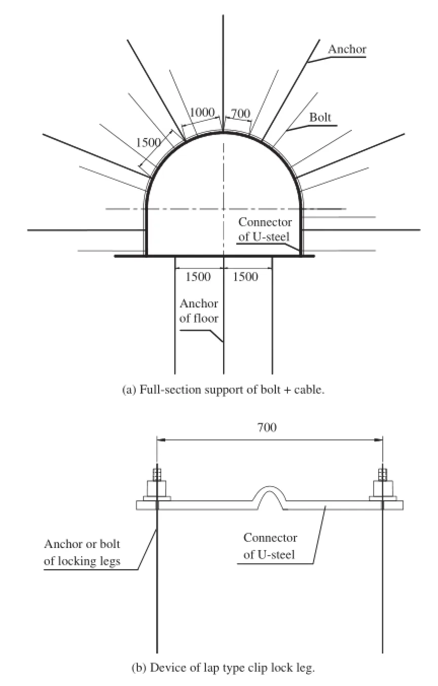
Fig.16.Bolt+cable support scheme of east main roadway(unit:mm).
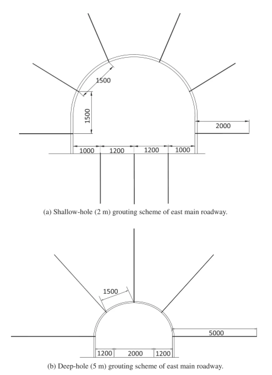
Fig.17.Grouting schemes(unit:mm).
The comprehensive support method of“bolt+wire mesh+U-steel arch bracket+shotcrete+grouting”+”cable”is employed. The monitoring results(Fig.18)show that,after 173 days,the relative convergence of two sidewalls reaches 208 mm on average, and the relative convergence of roof and foor reaches 448 mm.In addition,for the new roadways without using the comprehensive support method,the relative convergence of two sidewalls reaches 723 mm on average,and the relative convergence of roof and foor reaches 1201 mm after 143 days.It can be noted the that total deformation of the surrounding rocks in test section is much smaller than that of the new roadway without using the comprehensivesupport scheme,whichhas bettereffects on high stresssoft rock roadway with large deformations.
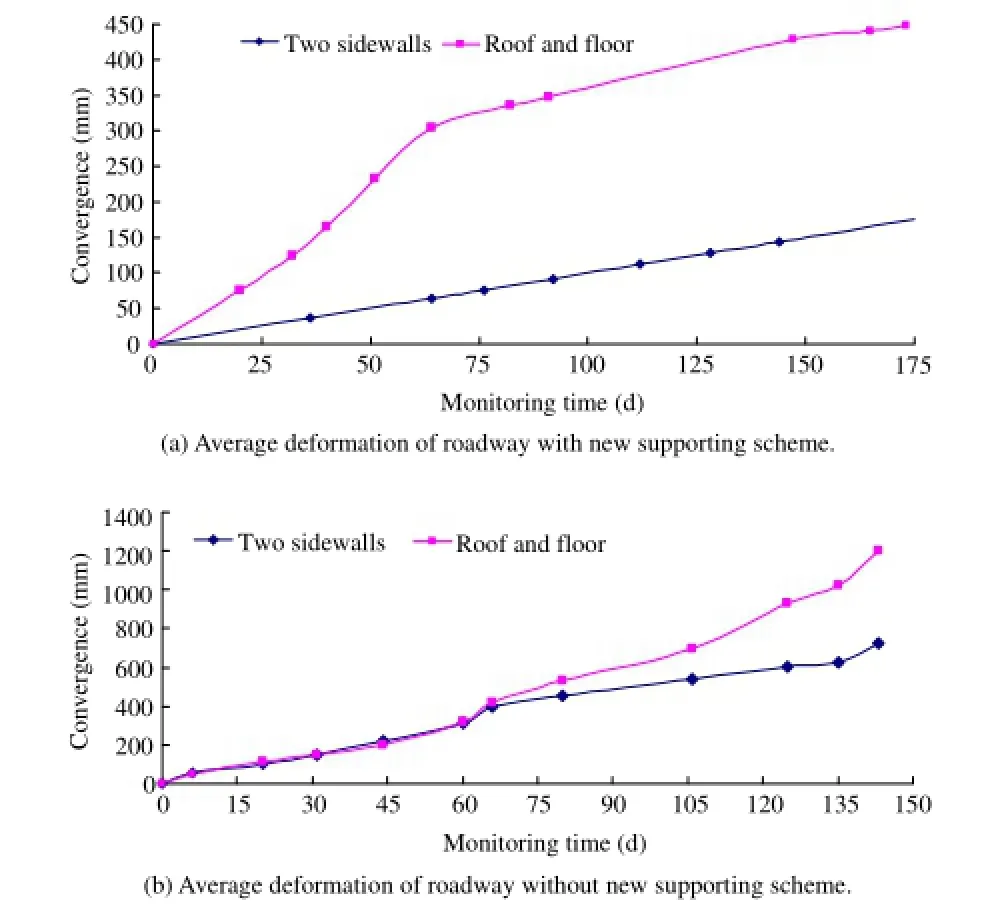
Fig.18.Deformation monitoring curves of roadway.
6.Conclusions
(1)Field investigation shows that the deformation of high stress soft surrounding rocks can be interpreted by large horizontal lateral pressure,which induces two sidewalls to be squeezed signifcantly.The large deformation of sidewalls can induce serious cracking,and thus strong caving and hollowing can occur.The high stress of roadway can lead to bottom bulge deformation and bending failure of the whole section,if not adequately supported.
(2)Soft rock plays an important role in the stability of high stress roadways.On one hand,unloading effect of rock mass due to excavation can change the stress state of surrounding rocks, from 3D to 2D.On the other hand,large deformation occurs for surrounding rocks of low strength under high stress.Therefore, rocks with low strength(e.g.argillaceous rock roadway)under the conditions of high stress can deform at sidewalls and/or roof and foor.
(3)Different weak interlayers or structures have different impacts on deformation and failure modes of roadway.For thin bedding within the roadway,the damage is mainly caused by the thin bedding occurrence.The damage between block rock and roadwaycan be attributed to the mainperformance of the block separated from the host rock,making the roadway surface signifcantly uneven.The small contact area between surrounding rocks and support structure can produce stress concentration likely to destroy the support structure and the roadway.Loose and fractured rocks under the action of high stress can burst easily,forming a large rupture area.In other words,if there is a weak interlayer crossing the roadway,it is prone to generate shear stress under the action of high stress. The accumulated shear stress can be larger than rock shear strength and rock fails consequently.
(4)One key factor likely to cause roadway deformation is the presence of geo-stress.Two sidewalls of roadway can be squeezed by large horizontal stress,and a peach-shaped roadway can be formed.Roadway roof subsidence is caused by large vertical stress.At the same time,stresses are transferred to sidewalls and foor gradually,increasing the convergence of roof and foor.Although a minor difference may exist between the vertical stress and horizontal stress,the whole section shrinkage of roadway can be induced in high stress state.When the maximum principal stress intersects with the roadway at a certain angle,a certain magnitude of stress can also be transferred to the foor,causing signifcant foor heave.
(5)For soft rocks in high stress condition,comprehensive supporting patterns should be used.Based on feld investigations and theoretical studies,different support patterns can be employed to control the deformation of roadway associated with different rock characteristics.
(6)Roadway deformation and failure caused by excavation have a close relation with the elevation difference of adjacent roadways.According to feld observations,for parallel roadways, large deformation of side walls or arch of roadway can be observed in the vicinity of the disturbance zone,which can also induce the whole section to deform seriously.Based on the surrounding rock deformation characteristics,excavation zones would be divided into excavation damaged zone,major infuence zone,minor infuence zone,and non-disturbance zone.
(7)Based on deformation characteristics of high stress soft rock roadway,the support principles,mitigations,and design methods are proposed.In this regard,the proposed comprehensive support method of“bolt+wire mesh+U-steel arch bracket+shotcrete+grouting”+“cable”was employed in east section of roadway of-850 m level in Qujiang coal mine.The monitoring results show that after 173-day monitoring,the average convergence of sidewalls reached 208 mm,the average relative convergence of roof and foor reached 448 mm,suggesting that this kind of supporting method for controlling large deformations of high stress soft rock roadway is effective.
Confict of interest
The authors wish to confrm that there are no known conficts of interest associated with this publication and there has been no signifcant fnancial support for this work that could have infuenced its outcome.
Acknowledgments
This work was fnancially supported by the National Natural Science Foundation of China(Grant Nos.51434006,51374105, 51374106)and Scientifc Research Fund of Hunan Provincial Education Department(Grant No.14A045).
Bai JB,Wang XY,Yao Z.Study of coupling support in soft rock roadway under high stress.Journal of China University of Mining and Technology 2007;36(4):421-5 (in Chinesse).
Cai MF,He MC,Liu DY.Rock mechanics and engineering.2nd ed.Beijing:Science Press;2013(in Chinese).
Chen X,Guo HY,Zhao P,Peng X,Wang SZ.Numerical modeling of large deformation and nonlinear frictional contact of excavation boundary of deep soft rock tunnel.Journal of Rock Mechanics and Geotechnical Engineering 2011;3(Supp.): 421-8.
Gonzalez-Nicieza C,Alvarez-Virgil AE,Gonzalez-Palacio C,Menendez-Diaz A.Infuence of the depth and shape of a tunnel in the application of the convergence-confnement method.Tunnelling and Underground Space Technology 2008;23(1):25-37.
Hayano K,Matsmoto M,Tatsuoka F,Koseki J.Study of triaxial creep testing method and model for creep deformation on sedimentary soft rocks.In:Proceedings of the 29th Symposium of Rock Mechanics.Tokyo,Japan:Committee of Rock Mechanics,Japan Society of Civil Engineers(JSCE);1999.p.8-14.
He MC,Guo ZB,Ren AW,Hu YG.Deep soft rock supporting technology of the repair project for transport tunnel in Liuhai coal mine.Chinese Journal of Geotechnical Engineering 2005;27(9):977-80(in Chinese).
He MC,Li GF,Wang J,Cai J.Study on supporting design for large area serious roof caving of deep soft rock roadway in Xing’an coal mine.Chinese Journal of Rock Mechanics and Engineering 2007;26(5):959-64(in Chinese).
He MC,Yuan Y,Wang XL,Wu ZQ,Liu C,Jiang YL.Control technology for large deformation of mesozoic compound soft rock in Xinjiang and its application. Chinese Journal of Rock Mechanics and Engineering 2013;32(3):433-41(in Chinese).
He MC.Latest progress of soft rock mechanics and engineering in China.Journal of Rock Mechanics and Geotechnical Engineering 2014;6(3):165-79.
Kanji MA.Critical issues in soft rocks.Journal of Rock Mechanics and Geotechnical Engineering 2014;6(3):186-95.
ˇSˇnupárek R,Koneˇcný P.Stability of roadways in coalmines alias rock mechanics in practice.Journal of Rock Mechanics and Geotechnical Engineering 2010;2(3): 281-8.
Verma AK,Singh TN.Assessment of tunnel instability-a numerical approach. Arabian Journal of Geosciences 2010;3(2):181-92.
Wang WJ,Peng G,Huang J.Research on high-strength coupling support technology of high stress extremely soft rock roadway.Journal of China Coal Society 2011;36(2):223-8(in Chinese).
Xie WB,Jing SG,Wang T,Ren YK,Zhang N.Structural stability of U-steel support and its control technology.Chinese Journal of Rock Mechanics and Engineering 2010;29(Supp.2):3743-8(in Chinese).
Yu WJ,Gao Q,Zhu CQ.Study of strength theory and application of overlap arch bearing body for deep soft surrounding rock.Chinese Journal of Rock Mechanics and Engineering 2010;29(10):2134-42(in Chinese).
Yu WJ,Wang WJ,Huang WZ,Wu H.Deformation mechanism and rework control technology of high stress and soft rock roadway.Journal of China Coal Society 2014;39(4):614-23(in Chinese).

Dr.Weijian Yu,is an associate professor(postdoctoral) and master supervisor in Hunan University of Science and Technology(HUST).He is the vice dean of School of Energy and Safety Engineering,the young core teacher training objects of Hunan Province,and the outstanding young teacher of HUST.Dr.Yu is mainly engaged in the study of the deep surrounding rock control,deposit mining and numerical calculation.In particular,he has much engineering practical experience and a solid theoretical foundation with respect to roadway support.He proposed nonlinear rock classifcation method and overlap arch bearing body strength theory,developed a number of new support structures and techniques which had obvious application results.Dr.Yu has published more than 60 papers on the academic journals of mining engineering including the Chinese Journal of Rock Mechanics and Engineering,Journal of China Coal Society,Chinese Journal of Geotechnical Engineering,and so on.More than 30 papers are included by EI and SCI with Dr.Yu as the frst author.He had published one book,High Stress and Structure Zone Surrounding Rock Control Mechanism and Engineering Practice.He was presented 3 awards of Science and Technology Progress and obtained more than 20 granted patents.Now,he managed 5 projects as PI,which are funded by the National Natural Science Foundation of China,Postdoctoral Foundation of China,Provincial Department of Education Research Key Project,Hunan Science and Technology Offce Project,and as a key member he participated in more than 30 projects supported by national“Eleventh Five-Year”plan and National Major Science and Technology Projects of China.In addition,during the Ph.D.from University of Science and Technology Beijing, he won the“top ten academic star”and other titles.
*Corresponding author.Tel.:+86 13100327785.
E-mail address:ywjlah@163.com(W.Yu).
Peer review under responsibility of Institute of Rock and Soil Mechanics,Chinese Academy of Sciences.
1674-7755©2015 Institute of Rock and Soil Mechanics,Chinese Academy of Sciences.Production and hosting by Elsevier B.V.All rights reserved.
http://dx.doi.org/10.1016/j.jrmge.2015.03.014
 Journal of Rock Mechanics and Geotechnical Engineering2015年4期
- Journal of Rock Mechanics and Geotechnical Engineering的其它文章
- A theoretical derivation of the Hoek-Brown failure criterion for rock materials
- Strength properties of soft clay treated with mixture of nano-SiO2and recycled polyester fber
- Case studies of high-sensitivity monitoring of natural and engineered slopes
- Key technologies of drilling process with raise boring method
- Analysis of horizontal displacement distribution caused by single advancing longwall panel excavation
- Susceptibility assessment of debris fows using the analytic hierarchy process method-A case study in Subao river valley,China
