静电纺丝法制备碳纳米纤维及其应用
岳孟斌,陈颖芝,白 宇,黄正宏*,许德平,康飞宇
(1.中国矿业大学(北京)化学与环境工程学院,北京 100083;2.清华大学材料学院,北京 100084)
20世纪60年代碳纤维已经成为重要的工业材料。近年来随着纳米材料的兴起,碳纳米纤维得到快速发展。碳纳米纤维因其比表面积大、导电和导热性好,被广泛地应用于吸附材料、储能材料、电极材料等。制备纳米纤维的方法有模板合成法[1]、相分离[2]、自组装[3]和静电纺丝法[4]等。 静电纺丝装置简单、成本低廉、工艺可控,可大批量制备出形状规则、直径分布均匀的纳米纤维,已成为有效制备纳米纤维材料的主要途径之一。将聚合物溶液或熔体通过静电纺丝过程制备成的无纺布纤维,进行高温碳化处理即得到碳纳米纤维。Fom Illals[6]于1934年发表了静电纺丝的第1个专利以来,已有百余种高分子纳米纤维通过静电纺丝的方法制得[5],近年来静电纺丝受到越来越多的关注。
1 静电纺丝原理
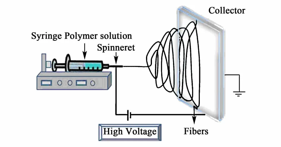
静电纺丝装置(图1)一般由高压直流电源发生器、注射泵、收集装置组成,静电纺丝时高分子溶液或者熔体装在注射泵中,高压直流电源正极连接注射针头,负极连接收集装置,收集装置一般直接接地,施加电压后在注射针头和收集装置间形成一个静电场,聚合物前驱体溶液以一定流速从纺丝针头流出,当针头处液滴所受电荷的排斥力可以克服表面张力时,液滴在静电力作用下被拉伸形成Taylor锥[7],当电压达到临界电压时,在Taylor锥尖端产生喷射液流,喷射液流表面电荷之间作用力和电场力的合力形成切向应力,抵抗掉液流的黏性应力后,使液流加速经过一个稳定拉伸阶段[8-9],在稳定运动一段时间后,电场力对射流的作用开始减弱,电荷间的相互作用力成为液流运动的主要推动力,液流中每一点电荷都受到相邻电荷的作用力,形成沿法向向外的力和沿轴向的斥力,法向向外地力使液流偏离轴向,沿轴向的斥力使液流拉伸变细,引起液流不稳定运动[10-11],在电场中形成螺旋运动,在运动过程中高分子溶液的溶剂挥发,高分子固化,形成纤维,收集在收集装置上。

图1 静电纺丝的实验装置[18]Fig.1 A setup for electrosp ining[18]
静电纺丝纤维收集方式对纤维收集状态有很大影响,采用平板收集时,静电纺丝制备的纤维是杂乱地堆积在一起,形成纤维膜。很多研究致力于改进收集装置,以便获得平行的纤维束、纱线或其他形状,如:采用滚筒收集法[12],使用一个圆筒以一定速度转动可以收集到一定排列形式的连续纤维;采用尖端收集法[13],制备排列度很高的纤维集合体;采用平行磁场法[14],使在收集装置区域形成一个磁场,可以制备出有序的纳米纤维。改变注射装置,采用两种溶液和两个注射泵可以进行同轴纺丝[15],制备核壳结构的纤维,应用在生物医学、电子元件等方面。采用多组针头电纺,可以提高聚合物纳米纤维的产率[16],采用1个注射针头和2种不相溶聚合物溶液可以电纺出双组分纤维[17]。
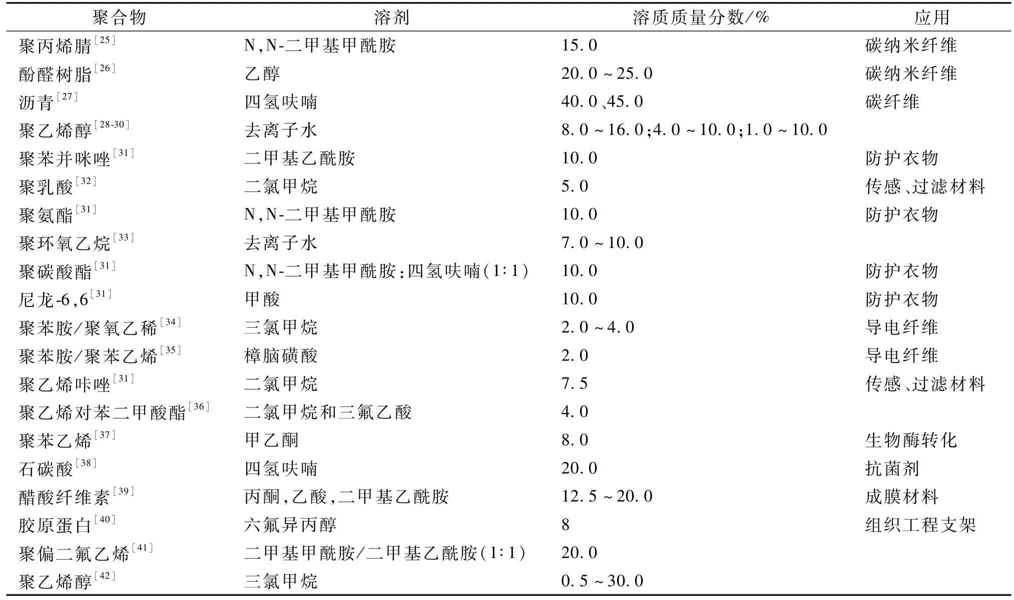
静电纺丝的前驱体有聚合物溶液和高温熔融聚合物。聚合物溶液是将聚合物溶于一种合适的溶剂,形成具有一定浓度、黏度、电导率的溶液,然后进行静电纺丝制备纳米纤维,表1列举了一些用于静电纺丝的聚合物种类;还有一部分高分子聚合物如聚乙烯[19]、尼龙 _12[20]等,能在高温熔融状态下进行静电纺丝,但需要在真空条件下进行。已有数十种高分子聚合物通过静电纺丝过程成功制备成纳米纤维。

表1 用于静电纺丝的聚合物Table 1 Polymers used for electrospinning
静电纺丝过程中聚合物溶液的性质、电纺参数以及环境因素都会对纺丝过程和产物形貌产生影响,调整好参数,才能得到均匀、连续的碳纤维。聚合物溶液性质包括表面张力、电导率和黏度,聚合物的相对分子质量、溶液浓度和溶剂种类以及添加剂对影响溶液的电导率、黏度等有很大影响,浓度越高,黏度越大,一般浓度要在一定的范围内纺丝才能顺利,过低时纤维有串珠,或者只是液滴,过高时也不能形成纤维。Koshi等[21]研究了不同重均相对分子质量的聚乙烯醇对纤维结构的影响,发现纤维直径随着聚合物相对分子质量的增大而变大,Wang[22]对热固性酚醛树脂/乙醇体系静电纺丝研究表明,当质量分数低于35%时,黏度调节至15~30 mPa·s时,可以纺出均匀连续的纤维。电纺参数包括溶液流速、施加电压、接受距离,每个聚合物溶液体系都有合适的接受距离、电压及流速范围。环境因素包括温度和湿度,静电纺丝过程很容易受到温度、湿度的影响[23],温度和湿度影响溶剂挥发速度,湿度会对纤维形貌和孔结构产生影响[24]。
2 电纺碳纳米纤维的特性
静电纺丝制备的纳米纤维要经过高温碳化过程转化成碳纳米纤维,碳化过程通常在惰性气氛保护下进行,使纤维发生氧化、交联等反应,纤维内部结构向碳碳结构转换。聚丙烯腈、沥青和酚醛纤维在碳化之前还要进行预氧化或稳定化过程,使纤维中分子环化和脱氢,转化为耐热结构[43]。聚丙烯腈通常在空气气氛中280℃进行预氧化处理,然后在惰性气氛中600~1 100℃碳化处理。经过稳定化和碳化处理,纤维重量减小,直径变小,有所收缩。
2.1 碳纳米纤维的孔结构
纤维碳化过程中由于纤维中前驱体的裂解和易挥发组分的挥发,在纤维中形成一些微孔(孔径<2 nm)甚至中孔(2~50 nm),使碳化后的碳纳米纤维比表面积变大,尤其是以酚醛树脂为原料,所得到的碳纳米纤维具有丰富孔结构。王磊[44]使用静电纺丝制备的热固性酚醛纤维毡,在600、800、1 000、1 200、1 400℃碳化处理后发现碳收率从53.8%下降到50.5%,比表面积由600℃时的530 m2/g上升到了1 000℃时的838 m2/g,随后又迅速下降至1 400℃时的8 m2/g,碳化过程中随着前驱体逐渐裂解形成越来越多的微孔[45],而温度过高时碳原子重排消除微孔形成大孔(孔径>50 nm)。为了增加比表面积和调整孔径分布,常使用水蒸气、CO2和KOH等试剂对碳纳米纤维进行活化处理,以获得不同比表面积和孔径分布的活性碳纳米纤维。
在聚合物前驱体溶液中加入不同的添加剂,可以获得不同孔径分布和比表面积的碳纤维。Zhang等[46]在聚丙烯腈前驱体溶液中加入聚乙烯吡咯烷酮,静电纺丝制备出纳米纤维,100℃水热条件下除去聚乙烯吡咯烷酮,再1 000℃碳化处理,聚乙烯吡咯烷酮的加入提高了聚丙烯腈碳纤维的比表面积和孔径分布。在纺丝前驱体溶液中加入模板、表面活性剂或MgO前驱体进行纺丝,可以调节纤维的中孔分布[47]。
2.2 碳纳米纤维的导电性
在用作电极材料、催化剂负载材料等时需要静电纺丝制备的碳纳米纤维具备高导电性。碳化温度较低时碳纳米纤维大多是无序结构,还包含很多非碳原子,高温处理可以使碳纳米纤维中非碳原子大大减少,同时提高碳纳米纤维中的石墨化结构,从而提高碳纳米纤维的导电性;但会使碳纳米纤维中的微孔、中孔减少。聚丙烯腈基碳纳米纤维由于需要预氧化处理以保持碳化后的纤维形貌,而不容易获得高度石墨化的碳纳米纤维。在2 800℃处理后电导率20 S/cm,但石墨化程度仍较低[48]。而聚酰亚胺碳纳米纤维不需要预氧化处理,高温处理后石墨化程度较高[49]。
在碳纳米纤维上负载多壁碳纳米管,可以提高碳纳米纤维的导电性。Guo[50]在聚丙烯腈静电纺丝前驱体溶液中加入多壁碳纳米管,制备出掺杂碳纳米管的碳纳米纤维,掺杂质量分数8%时使碳纳米纤维的导电性从0.86 S/cm提高到5.32 S/cm。
3 电纺碳纳米纤维的应用
静电纺丝制备的碳纳米纤维具有高导电性、高比表面积等特点,使其在电极材料、吸附材料、催化剂载体等方面得到广泛应用。
3.1 电容式脱盐电极材料
静电纺丝制备的碳纤维布具有较大比表面积,优异的导电性,柔韧性好,常用于电容式脱盐装置电极吸附材料。电容式脱盐是利用类似于电容器的装置去除水中离子的水处理技术,在用作电容式脱盐电极时,静电纺丝碳纤维布不需要额外处理,可以直接使用。Wang[51]通过静电纺丝制备出聚丙烯腈纳米纤维在800℃碳化、活化处理后,用作电容式脱盐电极材料,对初始浓度60 mg/L的氯化钠溶液的电容式吸附量达到3.1 mg/g,远高于未活化的碳纤维。王磊[44]使用静电纺丝制备的酚醛碳纤维毡作为电容式脱盐的电极材料,用以电吸附脱除水中初始浓度100 mg/L的氯化钠离子,电容式脱盐量达到5.4 mg/g。使用活化后的酚醛碳纤维,电容式脱盐量达到7.6 mg/g。Bai[52]在聚丙烯腈前驱体溶液中加入氧化石墨烯,将静电纺丝制备的纤维经过预氧化、碳化、活化处理后,制备出含氧化石墨烯的碳纳米纤维,氧化石墨烯的加入提高了纤维的中孔比率和导电性,用作电容式脱盐电极材料时比未添加氧化石墨烯的碳纳米纤维具有更高的吸附量。
3.2 电容器电极材料
多孔碳材料常用作电容器电极材料,商用的电容器一般使用活性碳材料。最新研究发现模板碳、碳纳米管和碳纳米纤维可用于提高电容器性能。静电纺丝可以制备网状碳纳米纤维,通过控制纳米纤维孔结构、负载离子到纳米碳纤维从而增加形成赝电容,提高电容器的性能。Iijima等[53]通过静电纺丝制备的聚丙烯腈基碳纳米纤维,在700、750和800℃水蒸气活化后,用作质量分数30%KOH水溶液的电容器电极材料,700℃活化样品比表面积达到1 230 m2/g,含有一些微孔,在10 mA/g的低放电电流密度下容量达到173 F/g,800℃活化样品比表面积为850 m2/g,含有一些中孔,在1 000 mA/g的高电流密度时电容达到120 F/g。Ju等[54]在聚丙烯腈溶液中掺入质量分数15%的醋酸纤维素静电纺丝制备的碳纳米纤维微孔比表面积919 m2/g,中孔比表面积241 m2/g,在6 mol/L的 KOH水溶液中电流密度1 mA/cm时电容达到245 F/g;在PAN/DMF前驱体溶液中掺入多壁碳纳米管静电纺丝制备的碳纳米纤维提高了电容器的性能,掺入质量分数3%的多壁碳纳米管使碳纳米纤维比表面积提高到1 170 m2/g,电导率达到0.98 S/cm,电容器电容值在6 mol/L的 KOH水溶液中达到 180 F/g[55]。为了增加赝电容,在PAN/DMF溶液中添加乙酰丙酮钌进行静电纺丝制备出负载钌离子的碳纳米纤维,负载质量分数7.31%钌的碳纳米纤维在6 mol/L的KOH中电容达到391 F/g,而未负载钌的碳纳米纤维电容仅为 140 F/g[56]。 Wang[57]在聚丙烯腈前驱体溶液中加入碳纳米管,制备出复合了碳纳米管的的碳纳米纤维,将制得的纤维浸入0.1 mol/L的KMnO4溶液中超声30 min,制备出负载了 MnO2的纤维,用作电容器电极时电容达到374 F/g。
3.3 锂离子二次电池阳极材料
静电纺丝制备的碳纳米纤维由于不需要添加导电添加剂和黏结剂,在用作锂离子二次电池阳极材料方面有一定优势,但是由于大部分纤维石墨化程度低,不能像天然石墨一样提供低的不可逆容量。Kim等[58]将制备的 PAN基碳纳米纤维1 000℃热处理后,电流密度30 mA/g时,可逆放电容量450 mA·h/g,略微高于天然石墨,而不可逆容量高达500 mA·h/g。Ji等[59]在PAN/DMF溶液中加入聚乳酸制备的碳纳米纤维,微孔孔容0.086 cm3/g,在电流密度50 mA/g,50次循环后可逆放电容量达到435 mA·h/g。Ji等[60]在PAN/DMF溶液中加入SiO2颗粒制备碳纳米纤维,然后滤除SiO2造孔,比表面积只有92 m2/g,但首次循环不可逆容量超过1 000 mA·h/g。在 PAN/DMF溶液中加入质量分数15%硅纳米颗粒,静电纺丝制备纳米纤维在700℃碳化处理,首次循环可逆放电容量高达855 mA·h/g,不可逆容量312 mA·h/g,比不加硅纳米颗粒的碳纳米纤维高的多。Ji等[61]在PAN/DMF前驱体溶液中加入乙酸锰,静电纺丝制备纳米纤维700℃碳化处理得到含有MnO和Mn3O4的纳米纤维,循环性能稳定。加入质量分数50%乙酸锰的碳纳米纤维稳定容量在600 mA·h/g,比不加乙酸锰的碳纳米纤维高的多。Steven等[62]将硅包覆在垂直碳纳米纤维表面,并将其用于锂离子二次电池阳极材料,结果显示该材料的电容量(以 1 g硅计)达到了 3 000~3 650 mA·h/g,而且经过100次充放电循环后电容量仍然保持89%。Kim等[63]以静电纺丝技术制备出可用于锂离子二次电池阳极材料的碳纤维,比表面积500~1 200 m2/g,比电容达到 35 ~202 F/g。 Chen[64]利用纺丝技术制备出高导电性的碳/钴纳米复合纤维,可逆容量大于 800 mA·h/g。Nan[65]在聚丙烯酸 /二甲基乙酰胺前驱体溶液中加入正硅酸乙酯和盐酸,通过静电纺丝制备出含有SiO2的碳纳米纤维,使用氢氟酸去除掉SiO2纳米粒子,得到的纤维比表面积达到950 m2/g,用作锂离子二次电池阳极材料时首次循环容量达到730 mA·h/g。
3.4 催化剂及催化剂载体材料
静电纺丝制备的碳纤维薄膜具有大比表面积,孔径发达,易于回收,可以重复使用,常用作催化剂载体。Wang[66]将静电纺丝制备的聚丙烯腈纤维进行活化和石墨化处理后用于室温下对NO的催化氧化,发现活性碳纳米纤维及1 900和2 400℃石墨化处理的碳纳米纤维对NO的催化氧化率分别是11%,38%和45%,石墨化的碳纳米纤维为NO催化氧化为NO2提供了更多的活性点位。陈莹莹[67]以PVP/Ti(OC4H9)4前驱体溶液电纺制备出纳米线,再在不同温度下煅烧制备出具有光催化性能的TiO2纳米线,对罗丹明B降解效果明显。Sundaramurthy[68]使用 Fe(acac)3/PVP乙醇溶液体系电纺出纤维,在500℃退火5 h,制备出a-Fe2O3纤维,对有机染料刚果红的光催化降解率达到90%。
3.5 吸附过滤材料
静电纺丝制备的碳纳米纤维形成的纤维膜气流阻力小,孔隙度高而孔径小,比表面积高,表面黏结性好,是高效的过滤材料。Bai[69]将静电纺丝制备的活性碳纳米纤维使用硝酸和硫酸进行氧化处理,处理后的活性碳纳米纤维表面官能团更加丰富,表面极性变大,对丁酮、乙醇等极性有机组分的吸附能力更强。将碳纳米纤维与其他机体复合,制成防护服,用作分子过滤、生化阻隔、吸收和降解有害气体。Gibson[70]在电纺法的纤维薄膜中引入把活性碳、碳纳米管和酶粒子引入电纺丝薄膜,制备化学生物保护膜,有效地捕捉空气中的粒子,具有防生化武器的基本功能。
4 结语
静电纺丝作为一种简便高效的制备方法,制备的碳纳米纤维所具有的独特优势,使其在功能材料领域里大有作为,已经引起人们广泛的关注。目前已有多种原材料可以用于静电纺丝,但最终产品大多都处于实验阶段,对其进行深入的基础和实用性研究具有重要意义,碳纳米纤维将会得到更广泛的应用。
[1]Martin C R.Membrane-Based synthesis of nanomaterials[J].Chemistry of Materials, 1996, 8(8):1 739_1 746
[2]Ma P X, Zhang R.Synthetic nano-scale fibrous extracellular matrix[J].Journal of Biomedical Materials Research,1999,16(1):60_72
[3]Whitesides G M, Grzybowski B.Self-Assembly at all scales[J].Science, 2002, 295(5 564):2 418_2 421
[4]丁彬,俞建勇.静电纺丝与纳米纤维[M].中国纺织出版社,2011
[5]Huang Z,Zhang Y,Kotaki M,et al.A review on polymer nanofibers by electrospinning and their applications in nanocomposites[J].Composites Science and Technology, 2003, 63(15):2 223_2 253
[6]Formhals A.Process and apparatus for preparing artificial threads:US 1975504 [P].1934_10_02
[7]Taylor G.Disintegration of water drops in an electric field[J].Proceedings of the Royal Society of London.Series A.Mathematical and Physical Sciences, 1964,280(1 382):383_397
[8]Hohman M M,Shin M,Rutledge G,et al.Electrospinning and electrically forced jets II.Applications[J].Physics of Fluids, 2001, 13(8):2 221_2 236
[9]Feng J.The stretching of an electrified non-Newtonian jet:A model for electrospinning[J].Physics of Fluids,2002,14(11):3 912_3 926
[10]Reneker D H,Yarin A L.Electrospinning jets and polymer nanofibers[J].Polymer, 2008, 49(10):2 387_2 425
[11]Reneker D H,Yarin A L, Fong H, et al.Bending instability of electrically charged liquid jets of polymer solutions in electrospinning[J].Journal of Applied Physics, 2000, 87(9):4 531_4 547
[12]Matthews JA, Wnek G E, Simpson D G, et al.Electrospinning of collagen nanofibers[J].Biomacro Molecules, 2002, 3(2):232_238
[13]Theron A, Zussman E, Yarin A L.Electrostatic fieldassisted alignment of electrospun nanofibres[J].Nano Technology, 2001, 12(3):384_390
[14]Wu Y, Yu J, He J, et al.Controlling stability of the electrospun fiber by magnetic field[J].Chaos, Solitons&Fractals, 2007, 32(1):5_7
[15]Sun Z, Zussman E, Yarin A L, et al.Compound coreshell polymer nanofibers by co-electrospinning[J].Advanced Materials, 2003, 15(22):1 929_1 932
[16]Yang Y, Jia Z, Li Q, et al.A shield ring enhanced equilateral hexagon distributed multi-needle electrospinning spinneret[J].Dielectrics and Electrical Insulation,IEEE Transactions, 2010, 17(5):1 592_1 601
[17]Lin T, Wang H, Wang X.Self-Crimping bicomponent nanofibers electrospun from polyacrylonitrile and elastomeric polyurethane[J].Advanced Materials, 2005, 17(22):2 699_2 703
[18]Bhardwaj N, Kundu SC.Electrospinning:A fascinating fiber fabrication technique[J].Biotechnology Advances, 2010, 28(3):325_347
[19]Larrondo L, Manley R S J.Electrostatic fiber spinning from polymer melts.I.Experimental observations on fiber formation and properties[J].Journal of Polymer Science:Polymer Physics Edition, 1981, 19(6):909_920
[20]Larrondo L, Manley R S J.Electrostatic fiber spinning from polymermelts.II.Examination of the flow field in an electrically driven jet[J].Journal of Polymer Science:Polymer Physics Edition, 1981, 19(6):921_932
[21]Kaoshi A, Yim K, Shivkumar S.Effect of molecular weight on fibrous PVA produced by electrospinning[J].Mater lett, 2004, 58(3):493_497
[22]Wang L, Huang Z, Yue M, et al.Preparation of flexible phenolic resin-based porous carbon fabrics by electrospinning[J].Chemical Engineering Journal, 2013,218:232_237
[23]Li D, McCann J T, Xia Y, et al.Electrospinning:A simple and versatile technique for producing ceramic nanofibers and nanotubes[J].Journal of the American Ceramic Society, 2006, 89(6):1 861_1 869
[24]Casper C L, Stephens JS, Tassi N G, et al.Controlling surface morphology of electrospun polystyrene fibers:Effect of humidity and molecular weight in the electrospinning process[J].Macromolecules, 2004, 37(2):573_578
[25]Dzenis Y A, Wen Y K.Continuous carbon nanofibers for nanofiber composites[J].Materials Research Society Symposium Proceedings, 2002, 702:173_181
[26]Buchko C J, Chen L, Shen Y, et al.Processing and microstructural characterization of porous biocompatible protein polymer thin films[J].Polymer, 1999, 40(26):7 397_7 407
[27]Kim B H,Wazir A H,Yang K,et al.Molecular structure effects of the pitches on preparation of activated carbon fibers fromelectrospinning[J].Carbon Lett, 2011,12:70_80
[28]Ding B, Kim H Y, Lee S C, et al.Preparation and characterization of a nanoscale poly(vinyl alcohol)fiber aggregate produced by an electrospinning method[J].Journal of Polymer Science, Part B:Polymer Physics,2002,40(13):1 261_1 268
[29]Senador A E, Shaw M T, Mather P T.Electrospinning of polymeric nanofibers:Analysis of jet formation[C]//MRS Proceedings.Cambridge University Press, 2000,661:KK5
[30]Morozov V N, Morozova T Y, Kallenbach N R.Atomic force microscopy of structures produced by electrospraying polymer solutions[J].International Journal of Mass Spectrometry, 1998, 178(3):143_159
[31]Schreuder-Gibson H, Gibson P, Senecal K, et al.Protective textile materials based on electrospun nanofibers[J].Journal of Advanced Materials, 2002, 34(3):44_55
[32]Bognitzki M,Czado W,Frese T, et al.Nanostructured fibers via electrospinning[J].Advanced Materials,2001,13(1):70_72
[33]Shin Y M,Hohman M M,Brenner M P,et al.Experimental characterization of electrospinning:The electrically forced jet and instabilities[J].Polymer, 2001, 42(25):09 955_09 967
[34]Norris ID, Shaker M M, Ko F K, et al.Electrostatic fabrication of ultrafine conducting fibers:Polyaniline/polyethylene oxide blends[J].Synthetic Metals, 2000,114(2):109_114
[35]MacDiarmid A G, Jones W E, Norris ID, et al.Electrostatically-Generated nanofibers of electronic polymers[J].Synthetic Metals, 2001, 119(1/3):27_30
[36]Reneker D H, Chun I.Nanometre diameter fibres of polymer, produced by electrospinning[J].Nanotechnology, 1996, 7(3):216
[37]Jia H,Zhu G, Vugrinovich B, et al.Enzyme-Carrying polymeric nanofibers prepared via electrospinning for use as unique biocatalysts[J].Biotechnology Progress,2002,18(5):1 027_1 032
[38]Kenawy E R, Abdel-Fattah Y R.Antimicrobial properties of modified and electrospun poly(vinyl phenol)[J].Macromolecular Bioscience, 2002,2(6):261_266
[39]Liu H, Hsieh Y L.Ultrafine fibrous cellulose membranes fromelectrospinning of cellulose acetate[J].Journal of Polymer Science Part B:Polymer Physics,2002,40(18):2 119_2 129
[40]Rho K S, Jeong L, Lee G, et al.Electrospinning of collagen nanofibers:Effects on the behavior of normal human keratinocytes and early-stage wound healing[J].Biomaterials, 2006, 27(8):1 452_1 461
[41]Koombhongse S, Liu W, Reneker D H.Flat polymer ribbons and other shapes by electrospinning[J].Journal of Polymer Science Part B:Polymer Physics, 2001, 39(21):2 598_2 606
[42]Warner SB, Buer A, Ugbolue SC, et al.A fundamental investigation of the formation and properties of electrospun fibers[J].National Textile Center Annual Report,1998:83_90
[43]Gupta A, Harrison I R.Newaspects in the oxidative stabilization of PAN-based carbon fibers[J].Carbon,1996,34(11):1 427_1 445
[44]王磊.静电纺丝制备酚醛基碳纤维毡及其电容式脱盐性能[D].北京:清华大学,2012
[45]Daley M A, Tandon D, Economy J, et al.Elucidating the porous structure of activated carbon fibers using direct and indirectmethods[J].Carbon, 1996, 34(10):1 191_1 200
[46]Zhang Z, Li X, Wang C, et al.Polyacrylonitrile and carbon nanofiberswith controllable nanoporous structures by electrospinning[J].Macromolecular Materials and Engineering, 2009, 294(10):673_678
[47]Inagaki M, Orikasa H, Morishita T.Morphology and pore control in carbon materials via temp lating[J].RSC Advances, 2011, 1(9):1 620_1 640
[48]Kim C, Yang K S, Kojima M, et al.Fabrication of electrospinning-derived carbon nanofiber webs for the anode material of lithium-ion secondary batteries[J].Advanced Functional Materials, 2006, 16(18):2 393_2 397
[49]Inagaki M,Takeichi T,Hishiyama Y,et al.High quality graphite films produced from aromatic polyimides[J].Chemistry and Physics of Carbon, 1999, 26:245_333
[50]Guo Q, Zhou X, Li X, et al.Supercapacitors based on hybrid carbon nanofibers containing multiwalled carbon nanotubes[J].Journal of Materials Chemistry, 2009,19(18):2 810_2 816
[51]Wang M, Huang Z, Wang L, et al.Electrospun ultrafine carbon fiber webs for electrochemical capacitive desalination[J].New Journal of Chemistry, 2010, 34(9):1 843_1 845
[52]Bai Y, Huang Z, Yu X, et al.Graphene oxide-embedded porous carbon nanofiber webs by electrospinning for capacitive deionization[J].Colloids and Surfaces A:Physicochemical and Engineering Aspects, 2014, 444:153_158
[53]Iijima S, Ichihashi T.Single-Shell carbon nanotubes of 1 nm diameter[J].Nature, 1993, 363:603_605
[54]Ju Y W,Park SH,Jung H R,et al.Electrospun activated carbon nanofibers electrodes based on polymer blends[J].Journal of the Electrochemical Society,2009,156(6):A489_A494
[55]Ju Y W,Choi G R, Jung H R,et al.Electrochemical properties of electrospun PAN/MWCNT carbon nanofibers electrodes coated with polypyrrole[J].Electrochimica Acta, 2008, 53(19):5 796_5 803
[56]Ju Y W,Choi G R,Jung H R,et al.A hydrous ruthenium oxide-carbon nanofibers composite electrodes prepared by electrospinning[J].Journal of the Electrochemical Society, 2007, 154(3):A192_A197
[57]Wang J, Yang Y, Huang Z, et al.Synthesis and electrochemical performance of MnO2/CNTs-embedded carbon nanofibers nanocomposites for supercapacitors[J].Electrochimica Acta, 2012, 75:213_219
[58]Kim C,Yang K S,Kojima M,et al.Fabrication of electrospinning-derived carbon nanofiber webs for the anode material of lithium-ion secondary batteries[J].Advanced Functional Materials, 2006, 16(18):2 393_2 397
[59]Ji L, Zhang X.Fabrication of porous carbon nanofibers and their application as anodematerials for rechargeable lithium-ion batteries[J].Nanotechnology, 2009, 20(15):155 705_155 711
[60]Ji L, Lin Z, Medford A J, et al.Porous carbon nanofibers fromelectrospun polyacrylonitrile/SiO2composites as an energy storage material[J].Carbon, 2009, 47(14):3 346_3 354
[61]Ji L, Medford A J, Zhang X.Porous carbon nanofibers loaded with manganese oxide particles:Formation mechanism and electrochemical performance as energy-storage materials[J].Journal of Materials Chemistry, 2009, 19(31):5 593_5 601
[62]Chen F, Peng X, Li T, et al.Mechanical characterization of single high-strength electrospun polyimide nanofibres[J].Journal of Physics D:Applied Physics, 2008,41(2):025308_025315
[63]Kim C.Electorehemical characterization of electorspun activated carbon naofibres as an electrode in supercapacitors[J].JPower Soucres, 2005, 142(1/2):382_388
[64]Wang L, Yu Y, Chen P, et al.Electrospun carbon-cobalt composite nanofiber as an anode material for lithiumion batteries[J].Scripta Materialia, 2008, 58(5):405_408
[65]Nan D, Wang J, Huang Z, et al.Highly porous carbon nanofibers fromelectrospun polyimide/SiO2hybrids as an improved anode for lithium-ion batteries[J].Electrochemistry Communications, 2008, 34:52_55
[66]Wang M, Huang Z, Shen K, et al.Catalytically oxidation of NO into NO2at room temperature by graphitized porous nanofibers[J].Catalysis Today, 2013, 201:109_114
[67]陈莹莹,侯建梅,张溪文,等.电纺制备 TiO2纳米线及煅烧对其光催化性能的影响[J].粉末冶金材料科学与工程,2009,13(6):352_355 Chen Yingying, Hou Jianmei, Zhang Xiwen, et al.Preparation of TiO2nanofibres and influence of calcination temperature on photocatalytic activity[J].Materials Science and Engineering of Powder Metallurgy, 2009,13(6):352_355(in Chinese)
[68]Sundaramurthy J, Kumar P S, Kalaivani M, et al.Superior photocatalytic behaviour of novel 1D nanobraid and nanoporous a-Fe2O3structures[J].RSC Advances, 2012, 2(21):8 201_8 208
[69]Bai Y, Huang Z, Kang F.Surface oxidation of activated electrospun carbon nanofibers and their adsorption performance for benzene, butanone and ethanol[J].Colloids and Surfaces A:Physicochemical and Engineering Aspects, 2014, 443:66_71
[70]Gibson P, Gibson H S, Rivid D.Transport properties of porous membrances based on electrospun nanofibers[J].Colloids and Surfaces, 2001, 187/188:469_481

