降低变速器、车桥和转向系统的功率损失(一)
Dr.F.-J.Joachim Dr.J.Börner Dr.N.Kurz ZF Friedrichshafen AG
1 前言
目前整个汽车工业都在尽可能降低CO2排放。各种因素都会影响车辆降低CO2的排放,从发动机到空气动力学、滚动阻力、轻量化设计、能量回收、热管理以及混合动力和电动化。本文主要探讨传动系统和变速器机械系统优化的可能性。传动系统总机械效率建立在变矩器/离合器、主变速器和驱动桥的效率上,如图1所示。
圆柱齿轮的99-99.8%效率已非常高。与之相比,由于存在更高的滑动摩擦圆锥齿轮和准双曲面齿轮的效率相对较低,图2根据变速器的种类,其效率约为85-97%[1]。
1 Introduction
The entire motor vehicle industry is researching possibilities for the reduction of CO2emissions.Various factors are influencing the reduction of vehicle CO2emissions,from the engine to aerodynamics,rolling resistance,lightweight design,energy sources,and heat management,as well as hybridization and electrification.The following article mainly investigates the mechanical optimization possibilities of drivelines and transmissions.The overall mechanical efficiency of the driveline is made up of the efficiencies of the converter assem-bly/clutch,main transmission and axle drive,Fig.1.

图1 车辆传动系统效率Fig.1 Vehicle driveline efficiency
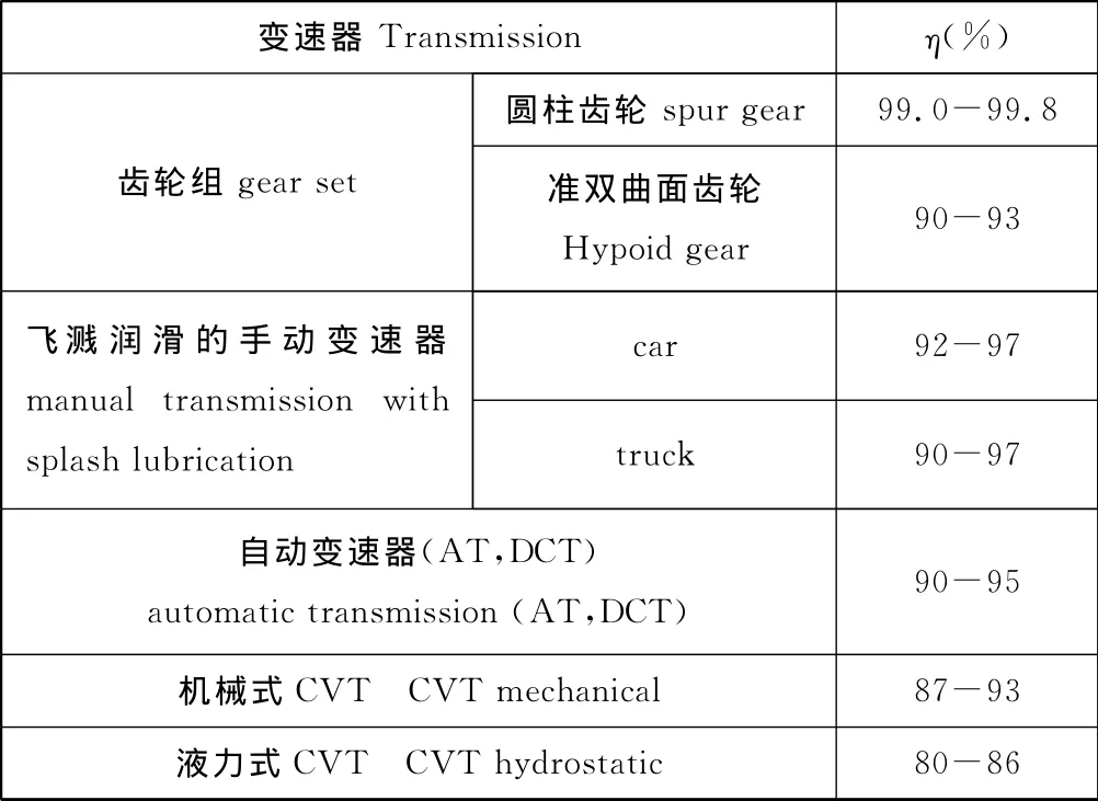
图2 车辆变速器和车辆效率的参考值Fig.2 Reference values for the efficiencies of gears and vehicle transmissions
2 传动系统的发展趋势
根据文献[2]所述,通过优化传动系统和底盘降低CO2排放的理论潜力约为60%。然而这是建立在一个几乎没有质量和损失的传动系统上。如图3[2]所测试,在2011年的潜力约为30%。对变速器效率的影响在图4中列出。这里必须在无负载和负载相关损失中作出选择。目前主要关注于润滑油优化、降低搅油损失、优化变矩器和油泵等。研究表明双离合器变速器可采用干式离合器。
Spur gears alone already reach a very good efficiency of 99-99.8%.Bevel gears and,above all,hypoids in rear axle drives have a clearly lower efficiency,by contrast,because of their higher glide fractions,
Fig.2.According to the type of transmission,the efficiency is approx.85-97%[1].
2 Development trends in drivelines
According to[2],there is a theoretical potential for CO2emissions reduction by optimizing the driveline and chassis by approx.60%.This would,however,presume an unrealizable,nearly massless and loss-free driveline.With the measures in Fig.3 ,[2]demonstrates a potential for an increase of approx.30%by the year 2011.Influences on transmission efficiency are listed in Fig.4.It is necessary here to choose between noload and load-dependent losses.The activities currently concentrate on the optimization of lubricants,reduction of the churning losses,optimization of the torque converters and pumps.It is being investigated for dual clutch transmissions what torque values allow for a dry clutch.
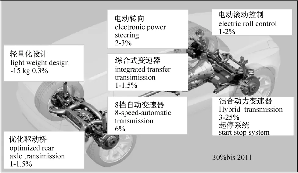
图3 传动系统优化的潜力和限制[2]Fig.3 Realizable potentials and limits of driveline optimization[2]

图4 对变速器效率的影响Fig.4 Influencies on transmission efficiency
3 润滑油的发展趋势
近年来发动机和变速器技术发展迅速。新型变速器,例如DCT已投入批量生产。现有种类的变速器在技术上也有改进。集中在优化换档舒适性、效率和可靠性方面。这为用户带来效益:驾驶舒适性提高、油耗降低和车辆无需经常维修。柴油机的发展对变速器影响深刻,因为转矩明显增大。

图5 ATF使用粘度对变速器牵引损失的影响Fig.5 Influence of the service viscosity(ATF)on the transmission drag losses
效率优化的变速器润滑油通常粘度低。在自动和手动变速器中使用该润滑油可降低1%的油耗,见图5.根据文献[3],在各种变速器中不同摩擦零部件的摩擦特性要求各异。自动变速器中的湿式多片离合器、DCT中的双离合器、工程机械驱动桥中的湿式制动器以及手动变速器中的同步器等对变速器润滑油的添加剂有着相当离散的要求。例如对于湿式离合器而言,要求具有相当高的静态和准静态摩擦系数用于确保转矩传递能力。这类要求通常与优化动态摩擦系数相关,后者还与离合器和制动器降噪有关。因此对于湿式多片离合器,为降低尖叫声,正摩擦系数在各种摩擦场合、变速器寿命周期和润滑油全寿命中都必须尽可能的高。抗热-氧化能力是变速器润滑油的一个重要性能,并且由于能够延长换油周期和密封变速器而变得更重要。未来粘度的降低受到限制,因为磨损和点蚀问题将显现,同时还有油泵泄漏等问题。因此必须对所谓的“燃油效率润滑油”的各种使用条件和影响因素进行检查。图6显示手动变速器采用低粘度润滑油后抗点蚀性能有所下降。在今后该缺点可能通过合适的添加剂得以补偿。
3 Trends in lubricant development
Engine and transmission technologies have developed rapidly in recent years.New transmission types,such as the dual clutch transmission,have gone into volume production.Existing transmission types were technically improved.Focus was placed on the optimization of shifting comfort,efficiency and reliability.This provided advantages for the customers:driving comfort improved,fuel consumption was reduced,and the vehicles did not have to go to the shop as frequently.Developments in engines have had the most influence on diesel engines in the capacity of the transmission,thanks to considerable increase in torque.
Efficiency-optimizing transmission oils mostly have lower viscosity.With automatic and manual transmissions,this reduces fuel consumption by up to 1%.,see Fig.5.According to[3],demands on the friction performance in the various friction elements in the respective transmissions are very special.Thus wet multidisk clutches in automatic transmissions,dual clutches in DCTs,wet brakes in construction equipment axles,and synchronizations in manual transmissions have very defined demands placed on the additives in the transmission oil.The goals here are mostly high static and quasistatic friction coefficients for protecting the torque capacity of,for example,wet multidisk clutches.This demand is often in contrast to an optimal dynamic friction coefficient,which in turn is meant to help prevent noise when clutching and braking.Thus for wet multidisk clutches,in order to prevent squeaks a positive friction coefficient is required as much as possible for all conceivable states of friction and over the service life of the transmission,with lifetime lubrication.Thermo-oxidative ageing resistance is an important property of transmission oils,which are becoming increasingly important as a result of longer oil change intervals and sealed transmissions.Future viscosity reductions are limited because wear and pitting resistance became critical,also the leakage of pumps ect.so for so called”fuel efficiency lubricants”all criteria and influences have to be checked.Fig.6 shows that the pitting performance for low viscosity manual transmission fluids is reduced.Maybe this negative effect can be compensated by suitable additive systems in the future.

图6 手动变速器采用低粘度润滑油对齿轮点蚀耐久性的影响Fig.6 Gear pitting durability for a manual transmission oil with lower viscosity[3]
4 润滑油性能试验
渗碳润滑油的摩擦特性在润滑油选择和开发中扮演着一个重要角色。ZF公司开发了一项性能试验用于评估传动系统的摩擦特性[7,11]。根据DIN 51354标准封闭式齿轮试验台的中心距为91.5 mm。设计原理见图7。与标准润滑油试验相比,在效率试验中相同的试验齿轮被安装在试验变速器和实际变速器中。高精度的动力测量组件安装在驱动电机和变速器之间。这样能够在应力循环中直接测量功率损失。该方法的测量精度远高于开式应力循环试验(发动机-试验变速器-制动器)。
4 Lubricant efficiency testing
The frictional behavior of the carburized lubricants plays an important role in the selection of lubricant and the development of oil.A ZF efficiency test was developed for evaluating the frictional behavior of gearings[7,11].A gear wheel foursquaretest rig in accordance with DIN 51354is used with a center distance of 91.5mm.The principle design is presented in Fig.7.In contrast to the standard oil test,in the efficiency test the same test gears are installed in the test transmission and the actual transmission.A highly precise power measurement hub is installed between the drive motor and the transmission.This makes it possible to directly measure the power loss introduced in the stress circuit.This approach is significantly more accurate than a measurement of performance difference in an open stress circuit(engine-test transmission-brake).

图7 有限功率损失和轮齿摩擦系数的车辆封闭试验台(根据DIN 51354标准)Fig.7 Vehicle four-square test rig(in accordance with DIN 51354)for limiting the power loss and teeth friction coefficient
所使用的转矩测量方法也适用于试验台的不同中心距。这样就能够在实际运行工况下研究批量生产的传动装置的摩擦特性。ZF效率试验采用标准的C型齿轮或者近似于批量生产的轿车变速器齿轮,见图8。齿轮摩擦系数的测量在不同转速和不同油底壳温度下进行。如果需要,试验条件包括圆周速度、表面应力(转矩)、润滑油条件等均能直接调整以满足特殊工况。在经过一个低转速和小转矩运行后,即可进行实际功率损失PV和相应的空载损失PW的测量。
Alternatively,the torque measurement method used can also be applied to a test rig with variable center distance.It is then possible to study the gearing friction behavior of volume-produced gearings under practical operating conditions.The ZF efficiency test employs the standard C gearing or,alternatively,apassenger car gearing that is close to volume production,Fig.8.The gear friction coefficients are determined at different rotation speeds and oil sump temperatures.If necessary,the test conditions-circumferential speed,surface stress(torque),lubrication conditions,etc.-can be adjusted directly to the values for each particular case.After phasing in with a low rotation speed and reduced torque,in the actual measuring run the total power loss PVand the corresponding idling power loss Pvoare determined.

图8 ZF公司效率试验用试验齿轮Fig.8 Test gearings for the ZF efficiency test
总的功率损失包括以下各部分:
PV=PVZP+PVZ0+PVLO+PVLP+PVD+PVX
这里:
PV=负载下的总功率损失,
PVZP=与负载相关的传动损失,
PVZ0=与负载无关的传动损失,
PVL0=与负载无关的轴承损失,
PVLP=与负载相关的轴承损失,
PVD=密封损失,PVX=其它损失。
与负载相关的轴承损失(PVLP)是根据轴承制造商所提供的手册加以考虑的。在随后进行的齿轮摩擦系数计算中使用以下公式:
PVZP=Pa*μm*HV,μm=PVZP/Pa*HV=MVZP/T1*HV
这里:
PVZP=负载相关的传动损失,
Pa=输入功率,
μm=齿轮平均摩擦系数,
HV=齿轮功耗因素=f (齿轮形貌)[12,14]。
图9显示了在FZG试验台上C型齿轮的功率损失测量值。从中可知,粘度低的润滑油或同种润滑油高油温时的功率损失下降。图10则显示了一个润滑油温度影响的实例和润滑油对齿轮摩擦系数的影响。摩擦系数随油温上升而下降。如果使用合成油,齿轮传动的摩擦系数还能进一步下降。图11是齿侧表面质量对摩擦系数的影响。齿面摩擦随表面精加工程度提高而降低。同样,摩擦特性也受到齿侧表面涂层的影响,见图12。确定摩擦系数的方法源于大量的研究。由ZF齿轮效率试验确定的摩擦系数可精确地转换为变速器的其它工况。
The total power loss is made up of the following components:
PV=PVZP+PVZ0+PVLO+PVLP+PVD+PVX
where
PV=total power loss measured under load,
PVZP=load-dependent gearing losses,
PVZ0=load-independent gearing losses,
PVL0=load-independent bearing losses,
PVLP=load-dependent bearing losses,
PVD=seal losses,PVX=other losses.
The load-dependent bearing losses(PVLP)are accounted for according to the data provided by the bearing manufacturer in the relevant bearing catalogs.The back calculation of the gear friction coefficient is performed using the following equation:
PVZP=Pa*μm*HV,μm=PVZP/Pa*HV=MVZP/T1*HV
where
PVZP=load-dependent gearing loss,
Pa=input power,
μm=median gear friction coefficient,
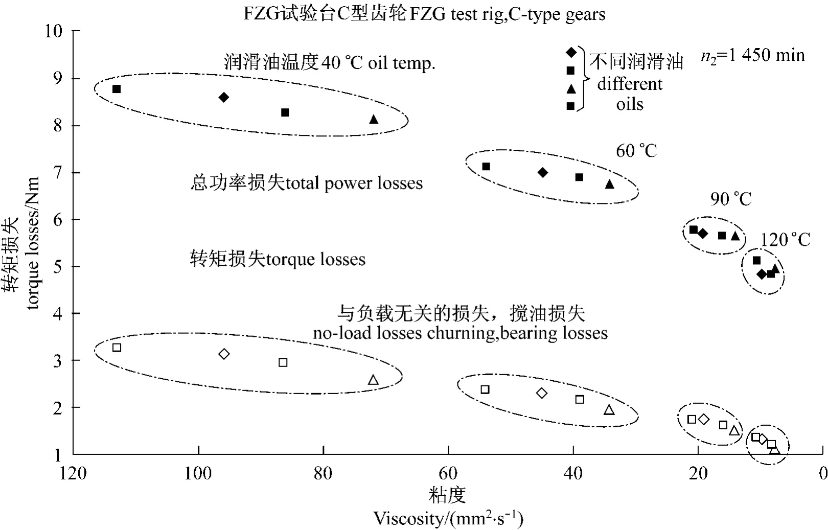
图9 在FZG试验台上粘度和温度对功率损失的影响Fig.9 Influence of viscosity and temperature on power losses in the FZG Test rig
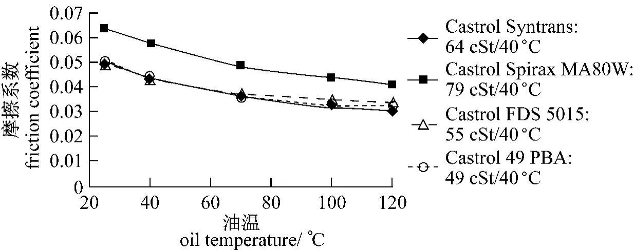
图10 润滑油品种对齿轮摩擦的影响Fig.10 Influence of lubricant type on gearing friction
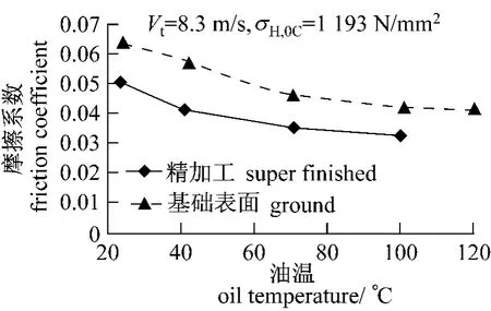
图11 表面精加工对齿轮摩擦系数的影响(润滑油:壳牌Spirax MA 80)Fig.11 Influence of surface finishing on gearing friction coefficient(oil:Shell Spirax MA 80)
HV=gear loss factor=f(gearing geometry)[12,14].

图12 表面涂层对齿轮摩擦系数的影响(润滑油:半合成油GL4)Fig.12 Influence of a coating on the gearing friction coefficient(oil:semi-synthetic GL4)
Fig.9 shows the measured powerlosses in the FZG-test-rig with C-type gearing.You can see that powerlosses are reduced with lower viscosities of different lubricants or with higher oil temperatures of the same lubricants.Fig.10 shows an example of the influence of the oil temperature and the lubricant on the gearing friction coefficient.The friction coefficient tends to decrease with the oil temperature.With the use of synthetic lubricant,the gearing friction can be lowered as well.Fig.11 shows the influence of the surface quality of the gear flank on the friction coefficient.The gear friction can be reduced with surface finishing (super finishing).The friction behavior can likewise be positively influenced by gear flank coating(here WC-C),Fig.12.The corresponding methods for determining the friction coefficient were derived on the basis of extensive investigations.It is thus possible to convert the friction coefficients determined in the ZF gearing efficiency test with good accuracy to other operating conditions in transmissions.
5 Calculation of gear losses
Simple formulations for the calculation of gearing power losses,such as the loss factor HV[12,14],are based on an assumed load distribution dependent on the number of meshing teeth.The calculation of gearing power losses can be improved if load distribution in the area of contact is considered,which the LVR[13]program does.This load distribution is usually determined on the basis of deformation influencing variables with a system of equations for the sum of forces in the plane of action.Determination of losses also requires consideration of the frictional forces acting at right angles to the plane of action,for the purpose of which the system of equations for the balance of torques on the driving gear needs to be formed and resolved.The torque resulting on the output is determined on the basis of the calculated distribution of normal and frictional forces,and the torque loss follows from the difference compared to the nominal output torque.The lever arm of the friction-induced torque changes with the distance from the pitch point.The frictional forces are defined as a product of vertical force and coefficient of friction.The coefficient of friction changes via gear engagement as a result of changing sliding conditions and oil viscosities whose action depend on the oil temperature in the area of tooth contact.A constant average coefficient of friction can be used for a sufficiently precise solution because the coefficient of friction does not vary significantly.The relative torque balance loss Vcan be calculated for any point on the line of contact with the following equation[2]:

TV2—torque loss on driven gear 2;
TN2—nominal torque on driven gear 2;
rb—base-circle radius;
αw—service pressure angle;
βb—base helix angle;
μ—coefficient of friction;
ζ—distance from pitch point。
The losses increase with increasing helix angle because the torque-producing tangential force on the base circle grows smaller than the tooth normal force which produces the friction.Assuming constant values for center distance and transverse contact ratio,the losses decrease with increasing ratio because the frictional force torque on the driven gear grows smaller compared to the nominal torque as a result of the greater basecircle radius.If the number of teeth is increased,the same effect occurs on both gears.Fig.13 shows the relative losses as they depend on the distance from the pitch point per base-circle radius at various ratios i for a friction coefficientμ=0.05and a base helix angleβb=30°.Also shown are the limits of the transverse path of contact with a transverse contact ratio =1.5for z1=12,24and 48.Reducing the distance of start and end of tooth contact from pitch point is the most effective measure to reduce power losses by changing tooth geometry.This goal can be achieved with reduced tooth height or increased operating pressure angle.A reduced tooth height is possible with lower tooth addendum as well as lower module with increased number of teeth.The use of lower module leads to larger overlap ratios which enable less noise excitation but root stresses increase simultaneously due to smaller cross sections.The potential of reducing losses by changing tooth geometry is shown in Fig.14.The way of reducing addendum and the option of increasing number of teeth is used with some examples starting from variant A.The operating pressure angle was increased additionally at some side steps.Increasing the number of teeth is most effective.Reduced addendum and increased operating pressure angle have less influence.Traces of noise excitation level versus load range of 10to 100%of nominal load are plotted in Fig.15 for some examples from Fig.14.Differences are clearly visible and they have to be considered in optimizing gears for low power loss.Improvements can be achieved with adjusted tooth modifications in doing so.Maximum stresses in case of nominal load are shown in Fig.16.Hertzian pressure is nearly constant for all variants.A distinctive increase of root stresses appears over decreasing loss factor from variant A to H.So an inadequate load-carrying capacity can be a result of minimizing power losses by changing tooth geometry.Finally the load distribution along the line of action is also influencing the level of power losses.Tooth loads at begin and end of contact can be reduced by increased tip relief,which decreases their large proportion to overall power loss as shown in Fig.17.Means of relieving start and end of contact for increased load-carrying capacity are also helpful for minimizing power losses of meshing gears.
5 计算齿轮损失
简单计算传动功率损失的公式如功耗因素HV[12,14]是建立在根据啮合齿数决定载荷分布的基础上。如果利用LVR[13]程序求出接触区域内的载荷分布,那么就能改进传动功率损失的计算方法。载荷分布通常由基础变形所确定,该变形的各项变量由啮合面上总作用力的方程给出。确定损失也需要考虑垂直作用在啮合面上的摩擦力,因此为平衡主动齿轮的转矩该方程必须可求解。输出端的转矩根据法向力和摩擦力计算得到,而转矩损失则通过比较与额定输出转矩之间的差异而确定。生产摩擦转矩的杠杆臂长随啮合点变化。摩擦力被定义成垂直力和摩擦系数的乘积。摩擦系数的变化取决于齿轮啮合时的滑动状况和润滑油粘度,而后者则取决于啮合区域的油温。由于摩擦系数变化不大,因此可用一个常数均值表示,并且具有足够高的精度。下式可用于计算转矩损失[2]:

TV2—主动齿轮2上的转矩损失;
TN2—作用在主动齿轮2上的名义转矩;
rb—基圆直径;
αw—压力角;
βb—基圆螺旋角;
μ—摩擦系数;
ζ—距啮合点的距离。

图13 在接触区轮齿摩擦造成的齿轮损失Fig.13 Relative gear loss resulting from tooth friction on the path of contact
损失随螺旋角增大而增大,因为基圆处转矩所产生的切向力的增长小于产生摩擦力的轮齿所受的法向力。假设中心距和端面重合度不变,损失随重合度增加而减小。因为作用在从动轮上的摩擦转矩的增加小于额定转矩的增加,这是由于基圆半径更大的缘故。如果啮合齿数增加,其效果相同。图13表明不同速比、摩擦系数μ=0.05和螺旋角βb=30°的情况下,相对损失与基圆半径到啮合区距离相关。图13还表明了在端面重合度为1.5和z1=12、24、48时的端面啮合线的限制值。
通过改变齿形以减少进入和脱离啮合距离能够明显降低功率损失。该方法可通过降低齿高或增大压力角获得。降低齿高的手段有降低齿顶高和采用小模数齿轮以增加齿数。减小模数将提高重迭程度,这能够降低噪声,但是齿根处应力显著增加,因为该处横截面变小。图14给出了改变齿形降低损失的潜力。减小齿高和增加齿数的实例见变量A。增大压力角也体现在该处。增加齿数非常有效。减小齿高和增大压力角的效果较差。从10%到100%载荷时的噪声水平线见图15。其差别非常明显,因此必须优化齿轮副以降低功率损失。调整齿轮修型可实现该目标。额定负荷下的最大应力见图16。接触应力在各种情况下基本保持恒定。齿根应力随着各种降低损失措施从变量A到变量H增加明显。因此通过改变齿形以降低承载能力为代价是能够将功率损失降至最小。最后,负荷沿啮合线的分布状况也影响功率损失的水平。增加齿端修缘能够降低进入啮合和脱开啮合时的轮齿载荷,齿端修缘能够大幅降低功率损失,详见图17。缓解开始和退出啮合以提高承载能力的措施引入有助于降低啮合齿轮的功率损失。
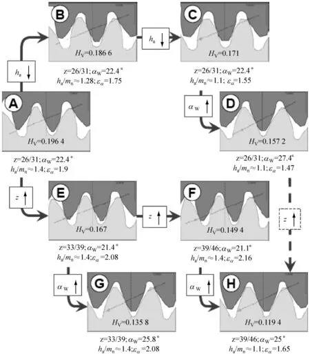
图14 不同齿轮副的Hv几何参数Fig.14 Geometric loss factor Hvfor different gearings

图15 图14不同齿轮副的噪声水平LAFig.15 Excitation Level LAfor different gear sets from Fig.14
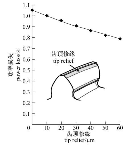
图16 计算图14各齿轮副小齿轮的根部应力和齿侧压力Fig.16 Calculated pinion root stresses and flank pressures for gear sets from Fig.14

