Experimental Study on Resistance and Longitudinal Motion of High-speed Air Cavity Craft in Regular Waves
DONG Wen-cai,OU Yong-peng
(Dept.of Naval Architecture & Ocean Eng.,Naval University of Engineering,Wuhan 430033,China)
1 Introduction
Air layers covering hull surface can reduce ship resistance effectively[1-7].Since 1960s,some institutions in China have been making efforts in theoretical study and experimental investigation of ship resistance reduction technology by air bubbly layer.Total resistance reduction rate has been reduced by 25% in still water for high speed craft models[8-14]and certain breakthrough on artificial cavity design has been made[9,11].But studies on hydrodynamic performance of high speed Air Cavity Craft(ACC)in waves almost remain untouched upon[15].Questions concerning the resistance reduction of ACC in waves,its motion performance in waves,the stability of bottom air cavity and optimum hull shapes in assuring cavity stability remain unanswered.In response to these uncertainties,the authors investigated the hydrodynamic performances of ACC in waves,especially the effect of air cavity on resistance reduction and longitudinal motion by a series of model experiments.
2 Test models and devices
2.1 Test models
Three test models,namely SM4,SM8 and SM9 are selected for the research,their main parameters are listed in table 1.

Tab.1 The main parameters of test models
In the table above,W is displacement,LOAis total length,LPis projected chine length,B is hull breadth,D is hull depth,BPXis maximum breadth over chine,BPTis breadth over chine at transom.βmis the deadrise angle at middle section,andβTis the deadrise angle at transom.
Model SM4 has an exceptionally blunt bow,narrow transom,with its maximum breadth over chine at front midship section,as shown in Fig.1.A transverse bottom step is set at the midship section of SM4,and its height varies with the bottom breadth,with a height of 3.35%BPXat keel and 0 at chine.The deadrise angle of SM4 is changed from 14° in front of the step to 11° behind the step,and then remains unchanged till stern.Air injection device is located right in front of the step,with orifice of 2 mm in diameter.

Model SM8 is modified from a conventional planing craft by hollowing the bottom,as shown in Fig.2.And the main parameters listed in Tab.1 refer to the hull before it was hollowed.The bottom hollow is located from midship near front up to stern,with its head being circular,and its width increasing gradually from front to transom.The ratio of hollow breadth at transom to breadth over chines at transom is 0.92.The hollow height is constant except at the front portion.The ratio of hollow height to maximum breadth of hull over chine is 0.012(models with ratio at 0.024 and 0.036 were also studied,which will be elaborated in Section 3.5).Air is injected at the head of the bottom through orifices with 2 mm in diameter.
Model SM9 has two chines,the inside one and outside one as shown in Fig.3.Tab.1 indicates only the length and width of the outside chine.The outside one is twisted downward,and can effectively reduce the spray of craft at high speed.The bottom of SM9 is twisted from midship up to stern,with a deadrise angle of 11.4° at midship and 0° at transom.Air is injected directly from bottom surface of the hull through the orifice with 2 mm in diameter,which is located at 4% of LPbehind midship.

2.2 Test devices
The test was carried out in the high speed hydrodynamic towing tank of China Special Vehicle Institution.The towing tank’s length is 510 m,breadth is 6.5 m,and depth is 5 m.The regular waves were made by a 16-paddle wavemaker,and examined by a fixed-point wave probe setting in 60 m front of the wavemaker.Total resistance was measured by a BLR-1 force sensor whose measurement range is 0~40 kgf,precision is 0.2%.The vertical motion acceleration was measured by FML-A100 accelerometers with measurement range of±3g and measurement error less than 1%.Pitch was measured by a TC-11A vertical gyroscope with a 0.1°precision.Heave was measured by a thread displacement sensor with a precision of 1%.
3 Test results and analysis
The longitudinal motion performance in regular waves under the influence of air cavity was tested on three test models at the wave length rangeλ/LP=0.7~5.5,the nominal wave height ratio hw/LP=0.022~0.033,the volume Froude number FV=3.634.Hereλ/LPrepresents the ratio of wave length to hull projected chine length,hw/LPrepresents the ratio of wave height to projected chine length.
3.1 The effects of air flow rate on total resistance
The effects of air flow rate on resistance of model SM4,SM8 and SM9 at FV=3.634 are illustrated in Fig.4 to Fig.6,in which Q represents air flow rate,Rtrepresents total resistance.The wave height ratios hw/LPare 0.022 in Fig.4 and Fig.6,and 0.022,0.027,0.033 in Fig.5.Under these tests the bottom hollow height of SM8 is 1.2% BPX.
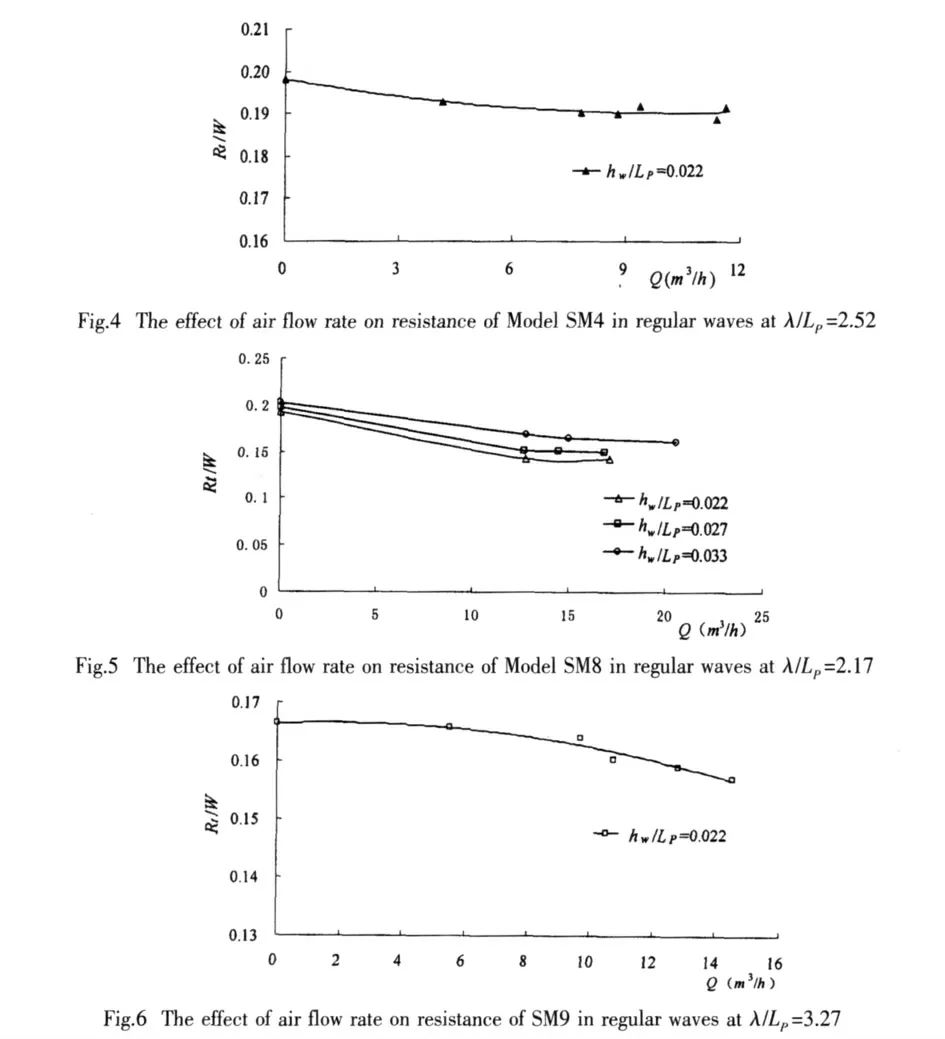
As is seen from Fig.4 to Fig.6,air injection reduces the resistance of model SM4,SM8 and SM9,and the resistance reduction rate increases with the increasing of air flow rate till air flow rate gets to saturation.The reduction rate almost keeps constant as air flow rate go over saturation.Obviously,the effect of air flow on resistance in regular waves is similar to that in still water[9].
3.2 The effects of hull form on the resistance reduction rate
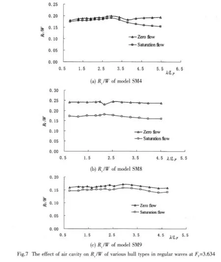
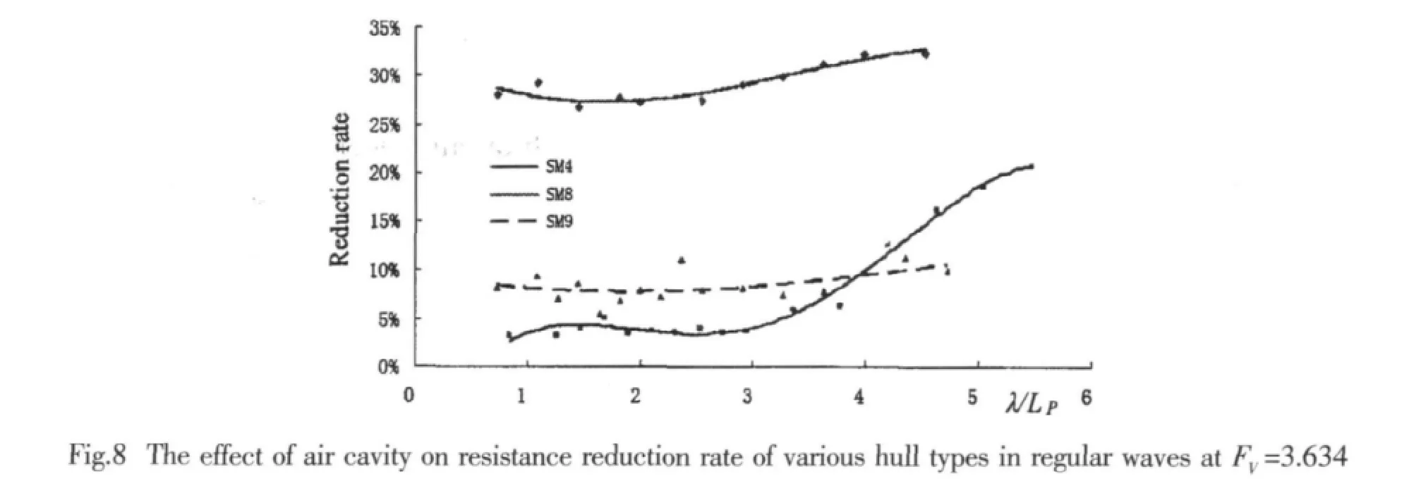
The effects of air cavity on resistance of different test models at saturation air flow rate in regular waves are presented in Fig.7.The resistance reduction rates of the three hull forms under saturation air flow rate are illustrated in Fig.8.The resistance reduction rateηis defined as follows:in the formula above,R refers to total resistance without air injection,and Rairis the total resistance with air injection.

Fig.7 and Fig.8 show that the influence of wave length on air injection’s resistance-reducing effects varies with hull forms.For model SM4,the reduction rate increases with the increase of wave length.It is 5% in short waves,and 20.5% in long waves.For model SM8 and SM9,wave length has little influence on resistance reduction rate,though difference in magnitude of reduction is obvious between the two.The resistance reduction rate of model SM8 is over 30% in the whole test wave length range with its maximal value up to 32.3%.The reduction rate of model SM9 remains at 8% over the whole wave length range.The above analysis indicates that hollowed bottom is reliable and effective in achieving stable resistance reduction rate in waves.
3.3 Bottom cavity
The effect of resistance reduction by air injection relates closely to the state of bottom air cavity.The stabler and bigger the cavity,the higher the resistance reduction rate.It was observed during testing that in saturated air flow the shape of air cavity fluctuates periodically from shape 1 to shape 2 as shown in the following figures.
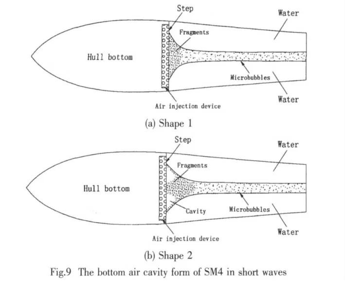
The bottom air cavity shapes of model SM4 in short waves and long waves are displayed in Fig.9 and Fig.10,respectively.Figs.9 and 10 reveal that the bottom air cavities of SM4 relate closely to wave length.The fragmentation of cavity is much more serious in short waves than that in long waves.A stable cavity can only be obtained in long waves.This accounts for the poor resistance reduction in short waves and effective reduction in long waves.
A typical air cavity of model SM8 is illustrated in Fig.11.The experiment shows that longitudinal waves have little effect on the shape of bottom air cavity of model SM8.Fig.11 shows that the shapes of cavity 1 and cavity 2 are almost the same,only slightly different at the stern portion.Thus it is well understood that the stability of SM8’s bottom air cavity is enhanced by the hollow,which is the primary reason for high resistance reduction rate of this hull form in waves.

The bottom cavity of model SM9 is similar to that of SM4 in short waves,but scarcely disturbed by wave length.Thus discussion of model SM9’s bottom cavity is passed over in this paper for briefness.
3.4 The effects of air cavity on the longitudinal motion performance
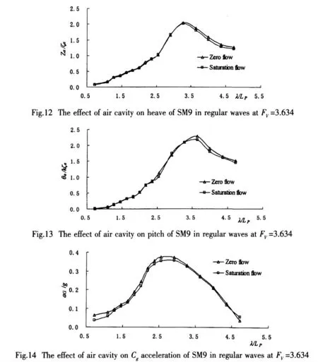
Model test results reveal that the effect of air cavity on the longitudinal motion performance is similar across the three models.Thus this paper only takes the test result of model SM9 for instance.
采用Excel和SPSS20.0软件对问卷调查数据进行基础部分的分析,包括样本人口统计学特征部分的频数分析,残障人士休闲习惯的频数分析等;问卷信度检验,用KMO值和Cronbach’s Alpha系数检验问卷各题题项的内部一致性;因子分析部分,用于提取影响残障人士的城市公园可进入性的主要因素;城市公园可进入性分析和测评,根据问卷获得的关于深圳市莲花山公园可进入性现状,残障人士目前的休闲特征和无障碍环境建设标准,以深圳莲花山公园为例,展开调查,并提出改进意见和建议.
In Fig.12 to Fig.14,the effect of air cavity on the SM9’s heave,pitch,and vertical acceleration of Cg(center of gravity),at FV=3.634 in saturated air flow are illustrated.And symbolsζa,k,Za,θaand aGrepresent wave amplitude,wave number,heave amplitude,pitch amplitude and vertical acceleration of Cg,respectively.
Fig.12 to Fig.14 show that bottom cavity only has a little effect on heave,pitch and vertical acceleration of Cg,while a certain decrease of motion amplitude is obtained in long waves.
3.5 The effects of bottom hollow height
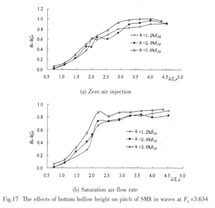
The effects of bottom hollow height on performance in waves were investigated on model SM8 which exhibits satisfying resistance reduction.Fig.15 to Fig.17 show the effect of SM8’s bottom hollow height on resistance,heaves and pitches in regular waves with and without air at FV=3.634.The bottom hollow height is 1.2% BPX,2.4% BPXand 3.6% BPX.
Without air injection the resistance increases with the bottom hollow height,but as the air flow reaches saturation,bottom hollow height shows little effect on the resistance,as shown in Fig.15.
Bottom hollow height has little effect on SM8’s heave at zero air injection as well as at saturation air flow,as seen in Fig.16.

As bottom hollow height increases,pitch increases,with or without air injection,as seen in Fig 17.
4 Conclusions
The main results of the study are summarized as follows:
(1)If air is injected,the resistance reduction rate in regular waves increases with air flow until it is saturated.
(2)The resistance reduction rate by air injection from the bottom surface of a craft is closely related to bottom hull design.It is about 5% in short waves and 20.5% in long waves to a hull with stepped bottom,up to 30% regardless of wave length to a hull with hollowed bottom,about 8% for all wave types to a craft with less spray.
(3)The air cavity changes periodically under the disturbance of waves.The stability of air cavity relates to hull type,and the bottom hollow is the most helpful for keeping the stability of cavity.
(4)Air cavity only slightly affects the heave,pitch,and the Cgacceleration,and the amplitude value of longitudinal motion reduces a little in long waves.
(5)For a craft with bottom hollow,the hollow height can affect the total resistance when no air is injected,while at saturation air flow it has little effect on the resistance.And the bottom hollow height has certain effect on the longitudinal motion,with or without air injection.
[1]Butuzov,et al.State of art in investigations and development for the ship on the artificial cavities[C]//International Workshop on Ship Hydrodynamics(IWSH’99).China,1999:1-14.
[2]Jang Jinho,et al.A practical application of air lubrication on a small high speed boat[C]//Practical Design of Ships and Other Floating Structures,PRAD’S 2001.Shanghai,China,2001:113-118.
[3]Go Seok-Ch’eon,Han Bam-Woo,Yoo Hee-Seok,Kim Hyochul.Formation of air cavity on the bottom of steeped semiplaning boat and its effects on resistance[C]//China-Korea Marine Hydrodynamic Meeting.Shanghai,China,1997:350-357.
[4]Fakhraee,Ahmad1,et al.Ship hull drag reduction using bottom air injection[C].Proceedings of the International Conference on Offshore Mechanics and Arctic Engineering-OMAE,2007,4:283-292.
[5]Steven L,Ceccio.Friction drag reduction of external flows with bubble and gas injection[J].Annual Review of Fluid Mechanics,2010,42:183-203.
[6]Kodama,Yoshiaki1,Kakugawa,et al.Experimental study on microbubbles and their applicability to ships for skin friction reduction[J].International Journal of Heat and Fluid Flow,2000,21:582-588.
[7]Gokcay,Odabasi,et al.Revisiting artificial air cavity concept for high speed craft[J].Ocean Engineering,2004,31(3-4):253-267.
[8]Dong Wencai,Guo Rixiu.Research progress of resistance reduction rate by bubbly layers[C].Proceedings of the 2004 Ship Hydrodynamics,2004,9:72-82.
[9]Dong Wencai,Ou Yongpeng,Guo Rixiu.Experimental study on the resistance of bottom hollowed air cavity planning craft[J].Journal of Ship Mechanics,2010,14(7):708-716.
[10]Dong Wencai,Guo Rixiu,Cheng Xiaolin,et al.Study on the mechanism of resistance reduction to the stepped planing craft by air injection[J].Journal of Ship Mechanics,2002,6(6):55-61.
[11]Dong Wencai,Liu Zhihua.Experimental study on the hull form of high-speed air cavity craft[C].The Ninth International Conference on Fast Sea Transportation,2007,9:264-269.
[12]Chen Hongxia,Ni Qijun,Yu Yangchun,et al.Experimental study on resistance reduction of air cavity ship[C]//Proceedings of China International Boat & High Performance Marine Vessels(HPMV)Conference 2010.Shanghai,China,2010,4:C13.
[13]Cai Jinqi.Ship resistance reduction by using thin layer of air film[J].Ship Building of China,2000,41(3):9-13.
[14]Wang Jiamei,Jiang Mansong,Zhen Xiaowei,et al.Study of drag reduction of vessel model by microbubble with different injection forms in the towing basin[J].Journal of Huazhong University of Science and Technology,2004,32(12):78-80.
[15]Ou Yongpeng,Dong Wencai,Xu yong.Experimental study on the longitudinal motion performances of bottom hollowed high speed air cavity craft in regular wave[J].Ship Building of China,2010,51(3):1-10.
- 船舶力学的其它文章
- Numerical Simulation of Pressure Distribution in Vertical Water-entry Cavity
- Study of a Hybrid Method Based on FDM and MLSFD Method
- Parametric Identification of AUV’s Maneuvering Motion Based on Support Vector Machines
- Research on Calculation Methods of Hydrodynamic Coefficients for Sections with Complex Shape
- Investigation of Sea Wave and Structure Modelling for Fatigue Assessment of Offshore Structures

