Study of a Hybrid Method Based on FDM and MLSFD Method
CHEN Shan-qun,LIAO Bin,LI Hai-feng
(1.College of Mechanical and Automotive Engineering,Anhui Polytechnic University,Wuhu 241000,China;2.An Hui Key Laboratory of Advanced Numerical Control & Servo Technology,Wuhu 241000,China;3.China Guangdong Nuclear Wind Power Co.,Ltd.South China Branch,Shenzhen 518031,China)
1 Introduction
Finite Element Method(FEM),Finite Difference Method(FDM)and Finite Volume Method(FVM)are conventional numerical methods to analyze and simulate the fluid dynamic problems.One common characteristic of all these methods is that they need to generate Eulerina(FDM or FVM)mesh,or Lagrangian(FEM)mesh.With the further research of flow problems,the problems with complex regions are gradually increasing in practical engineering.These meshbased numerical methods confront difficulties in mesh generation.When dealing with the complex region the computational costs associated with mesh generation are large.In addition,the mesh quality is not stable,which will directly affect the success of numerical simulation.The meshfree methods arising in recent years are free from constraints of the mesh.One attractive property of these methods is the computational ease of adding and subtracting nodes from the pre-existing nodes.Furthermore,nodes generated in meshfree methods can fit the complex boundary better than traditional mesh.Therefore,the meshfree methods provide a new thought in solving fluid dynamics problems.
In the present study,a hybrid method,which combines the conventional finite difference method[1]and the meshfree least square-based finite difference method(MLSFD)[2],is proposed.These two methods are coupled both in grid generation and computing format.Fortran language is used to compile the running program.The hybrid method is validated by simulating the flow field around a 2D circular cylinder.The feasibility and convergence of the hybrid method are investigated.
2 Related concepts of meshfree method
2.1 Support domain
Take 2D space for instance,as shown in Fig.1,n nodes are distributed for discretization in solution domainΩ,all dots are independent computational nodes.When a central node(concentric circle)is selected arbitrarily from the computational nodes,the function value of the central point can be approximated by algebraic functions at its neighbouring points.We call the domainΩ1the support domain of central node[3].
Theoretically,the shape of support domain in meshfree method can be any plane figures.But for convenience,we usually choose a appropriate circle or rectangular domain for computation.In Fig.1 there are two different support domains.To take circular domain for instance,concentric circle pot named the central node and black solid pots named supporting nodes form“cloud nodes”together for computing the function value of central node.While outer nodes(hollow circle pots)are not involved in computing the function value of central node,so they have no influence on central node.
2.2 Point generation technique
In meshfree methods computational nodes in the domain can be distributed randomly.However,taking into account the convenience of distribution nodes and satisfaction of the normal boundary conditions,in principle,we distribute nodes according to the shape of computational domain and boundary.With the sample of circular obstacle and straight line we can distribute nodes along the radial of circle and vertical of straight line as shown in Fig.2,computational nodes are distributed in the vicinity of boundary for more accurate results.

2.3 Selection principle of nodes within support domain
When support domain is determined,not all points in domain are involved in approximation computation of central node.In this paper,two solutions are presented for nodes selection[4]:
(1)If the number of computational nodes is n,a cloud of n nodes in the vicinity of center node are chosen.This method is quite simple and less computational cost.

(2)Based on the first method,another selection is carried out for the n points.Firstly,the selected points need to distribute uniformly around the central node(see Fig.3(a)).Then the case that there are no points in large sector area should be avoided(see Fig.3(b)).Finally,the case that there are a great many points in small sector area should be avoided,too(see Fig.3(c)).Therefore the suitable sector angleαis taken in 40°~120° to guarantee the node number in computation is between 4~9.If the angle of two nodes linked with central node is too small and one of them has to be discarded,the one with less distance from the central node is preserved.In Fig.3(c),suppose we preserve node 1 and discard node 2.Although this method requires much more computation time than the former one,distribution of computational points is uniform.Because of the different density of discrete points,the number of computational nodes is indefinite.
2.4 Weighting function
When the functional values of supporting points approximate those of the central point,suppose that the total amount of approximation error is fixed.One would normally prefer the approximation error to be small in the crucial central region around the reference node,and be willing to tolerate higher errors for points further out,since the latter is expected to have smaller influence on the desired derivatives.The redistribution of errors can be achieved by introducing a distance-related weighting function.
To take a circular support domain for example,several commonly used weighting functions are represented as

3 MLSFD method
3.1 Development of two-dimensional meshfree FD schemes
MLSFD uses the 2D Taylor series expansion[5]to approximate the functional value at the supporting node.The functional value of supporting node j near central node O can be approximated by the functional value and its derivatives at the node O by equations as follows:

whereΔxj=xj-xo,Δyj=yj-yo,(xj,yj)denotes the Cartesian coordinates of node j.
Suppose that Eq.(1)is truncated to the third-order derivatives,it has nine unknowns like the conventional FD scheme,we need nine equations to solve for these nine unknowns.This can be achieved by applying 2D Taylor series expansion in Eq.(1)at nine neighboring points according to the method in section 2.3,we can choose nine points conformable to the requirement within support domain for expansion.Application of Eq.(1)at nine neighboring points gives

In above equations,the subscript o denotes functional value and derivative at central node,subscript j (j=1,2,3,…,9)denotes functional value and derivative at node j in support domain.
By definingΔφ=[φ1-φo,φ2-φo,…,φ9-φo],ST=[s1,s2,…,s9],we can further assemble Eq.(2)into the following succinct matrix form:

The square matrix S contains all the geometric information about the distribution of the supporting nodes.If the matrix S is non-singular,the derivative vector dφcan be obtained as

Application of Eq.(4)to discretize derivatives in the differential equations yields the meshfree finite-difference equations.
3.2 Application of least-square technique
One kind of case will occur when using meshfree FD schemes to approximate derivatives is that if the supporting nodes are very close to each other,the matrix S tends to become singular and ill-conditioned.This difficulty is not easy to be resolved because little is known about the effects of node distribution on the conditioning of the matrix,except for the case where all the supporting nodes are located on the same straight line.For numerical implementation,we would have to check and ensure that the matrix S is well-conditioned and inversed at every node in the computational domain.However,it will greatly increase the computational cost.
In order to avoid cumbersome examination process,the least square technique[6]is introduced to optimize the approximation of the vector dφin our work.The least-squares technique allows an optimized approximation derived from an over-determined set of equations.Therefore,the problem of singular coefficient matrix is circumvented by means of using more supporting points(more than the unknowns).
Suppose that the optimal approximation of the derivative vector at central node o is b.Similar to Eq.(2),the functional value of supporting nodes can be approximated by

Eq.(5)is applied at n n≥()9 supporting points in the domain.The vector b(optimal approximation of the derivative vector dφ)can be obtained by the least square technique.We define the approximation error as E is truncated to the third-order derivatives.

To minimize the error,we need to set

Substituting Eq.(6)into Eq.(7)gives

where sj,krepresents the entry of the matrix S at jth row and kth column,which is the kth coefficient of derivative corresponding to the jth calculating node.bkrepresents the element of derivative vector dφat kth row,which is the kth derivative in 2D Taylor series.
Eq.(8)can be further simplified as

Noticing that(sj,m)=(sm,j)T,Eq.(9)can be rewritten in the following form of matrix:

Thus,we get the explicit expression for the optimal derivative approximation by leastsquare technique.
3.3 Weighted MLSFD method
Through the use of least-square technique to avoid the singularity of the coefficient matrix,it makes almost even error-distribution at the supporting points.So,it still needs to be improved as an approximation scheme.The least-square approximation(6)assumes the square errors to be uniformly distributed across the supporting points.However,for a given amount of total error,one would normally prefer the approximation error to be small in the central region around the central node,where the derivatives are evaluated,and be willing to tolerate higher errors for points further out,since the latter is expected to have smaller influence on the desired derivatives.For redistribution of errors,we need to introduce a distance-related weight-ing function that assigns greater weightage to points near the central node.
Substituting weight functions into Eq.(11)gives

where W is a n×n diagonal matrix formed by applying equations introduced in section2.4 at n supporting points,W=diag (W1,W2,W3,…,Wn).

Up to now we fully derived the free-mesh least-squares-based finite difference method.Although the idea of this method originated from traditional finite difference techniques,but it is independent on the mesh,so it is a truly meshfree method.
4 Hybrid method of conventional FD scheme and MLSFD method
For different algorithms between conventional FD method and MLSFD method,the spatial discretization methods are not the same.In conventional FD method,differential mesh needs to be generated at the Cartesian coordinate system or transformed from irregular mesh by coordinate transformation techniques,However,MLSFD method does not require mesh generation,as long as according to the need for resolutions and boundary shape it distributes nodes randomly in different density.Thus,the pre-treatment of the hybrid method adopts a type of composite mesh with total mesh and local meshfree for spatial discretization.
4.1 Treatment for composite mesh intersection
After the composite mesh generated there is a transition zone between differential mesh and meshfree nodes,as shown in Fig.4,where mesh nodes and meshfree nodes overlap each other.To ensure no chaos in overlap region,the nodes among the intersection have to be categorized and selected[8],so that the whole area is discretized well,for the convenience of the subsequent calculation.
Fig.4 provides a graphical representation of the six types of nodes before categorization and selection.
(1)Finite difference nodes,namely,finite-difference coordinate mesh node,which are represented by the symbol of big hollow circle.This group of nodes satisfy orthogonality with each other,at which the FD method is used directly.Most of these nodes apply different difference scheme to achieve appropriate precision,while,partial nodes near meshfree region have to do reduction and subtraction computation.
(2)Meshfree field nodes,which are marked by diamond.Although this type of nodes are in FD region,the conventional FD scheme can not be used.The reason for this is that location of the nodes is special.Namely,it is FD region on one side and meshfree region on the other.Therefore the surrounding nodes are not likely to meet the requirement for FD computation.Meshfree method can be used to do numerical discretization at these nodes.These nodes act as the“exchange layer”and bridge the meshfree and FD region.The information exchange will take place in the“exchange layer”.On one hand,these nodes are taken for FD computation of finite difference nodes.On the other hand,the local support of mesh-free nodes near or inside the exchange layer can include the points in the FD region.Therefore,the layer of these nodes serves as a virtual boundary,which separates the two different regions and also makes connection with each other.
(3)Intersection nodes,as indicated by the cross diamond.These nodes are at the intersection of the surface and FD mesh,which can complement discrete points of boundary for improving accuracy.In practical computation we can not consider intersection nodes if the discrete points of boundary are enough.
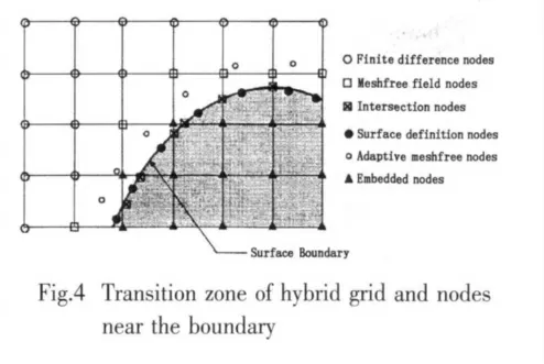
(4)Surface definition nodes,as marked by black solid pots.These nodes are discretized associated with the body geometry,so they can describe complex boundary shape in computation,surface definition nodes are employed when adding boundary conditions.In addition,if we compile program for node distribution,meshfree nodes near body boundary are distributed on the basis of surface definition nodes.
(5)Adaptive meshfree node,as the symbol of small hollow circle.According to a definite principle in node distribution,nodes consistent with the shape of the body are generated in several layers near the body,in order to capture the information in the vicinity of the boundary for meshfree nodes,they are covered at length in previous section.
(6)Embedded node,as the symbol of filled rectangular.These nodes in FD mesh are of no use for calculation,which can be categorized into two types:those embedded within the body;those located in the area between the object boundary and artificial boundary consisting of meshfree field nodes.
4.2 Coupling of hybrid method
Two different algorithms in the hybrid method yield the coupling problems.The treatment of coupling problems occurred within transition region in hybrid mesh is the key technique to hybrid method generation,which decides whether the information can be transmitted smoothly between the two different regions.
In Fig.5,the domain is divided into left and right sub-domain.Namely,left sub-domain is FD mesh region by a letter A and right sub-domain is meshfree region by a letter B.Nodes 7,8,9 are meshfree region nodes.Take nodes 5 and 9 for instance,the FD schemes in mesh region A are written as:

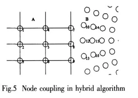
whereΔx andΔy denote the spatial step per unit in the x and y direction,u and v represent the components of velocity in the x and y direction.The discrete schemes of Eqs.(16)and(17)are center differential and forward differential,respectively.
In meshfree region B,taken node 12 for example.If four nodes(8,10,15,13)are chosen for approximation of spatial derivatives,Eq.(15)can be obtained as the following form:

Node 8 in transition region is involved in the computation of both regions.At this node,the computation is coupling under the condition as[9]:

This condition is applied to all nodes in transition area.
5 Simulation of incompressible inviscid flow by hybrid method
5.1 2D Laplace equation and boundary conditions
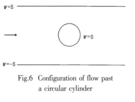
The feasibility of the present hybrid method is verified by simulating the incompressible inviscid flow over a 2D circular cylinder.The governing function is Laplace function in terms of stream function:

The flow domain and boundary conditions are depicted in Fig.6.The values of stream function on the upper,lower and circle cylinder boundaries are given asψ=5,ψ=-5 andψ=0,respectively.
5.2 Hybrid mesh generation
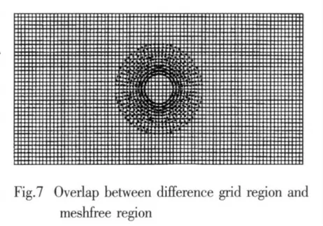
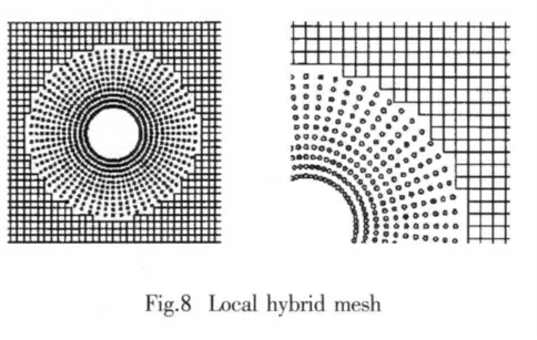
In this study,we set the size of computational domain to 10×20 and 1 the radius of the cylinder to 1.The detail approaches for node distribution are summarized as follows:Firstly,we generate FD mesh in the whole domain.Then,the cylinder boundary is divided equally into 64 points.Starting from these points,meshfree nodes of 10 lays are generated in normal direction to outside with a distance of 0.2 between each lay.Thus the meshfree region is the area between two concentric circles with the radius of 1 and 3.Up to now,with the advent of the overlap region in meshfree region,as shown in Fig.7,hybrid mesh generation is not yet complete.
In overlap area there are FD nodes and also meshfree nodes,which will make the computation in trouble.Here we reject FD nodes because in meshfree region only meshfree nodes needed for calculation.In our study,the radius of meshfree region is defined as R.When the distance from the FD nodes to cylinder center is less than or equal to R,the nodes do not participate in calculation.After the treatment in overlap region,finally,the hybrid mesh is obtained as shown in Fig.8.
5.3 Governing function discretization
In FD mesh region,the governing function in central-difference scheme[10]is derived from 2D Taylor series expansion,which can be written in terms of 2D subscript characters as

In meshfree region,the governing equation is discretized by using the MLSFD method,

5.4 Results and convergence analysis
In this study,Gauss-Seidel iteration is adopted and computation is terminated when residual error is less than 10-7.Isolines of stream function for flow overt a circular cylinder are obtained,as shown in Fig.9.The numerical results achieved by the present method agree well with the analytical solutions[11].
In addition,the convergence behavior of the present hybrid method is investigated.Define that the cylinder boundary is divided equally into d points,as well as,c lays of meshfree nodes are generated in normal direction to outside with a fixed distance.In the meshfree support domain,a cloud of n nodes nearest to the center node are chosen for calculation.Thus the“mesh”size in meshfree domain is simply expressed as c×d×n.For simplicity,we reduce computational domain to 10×10 and the radius value is the same as before.Two uniform distributions of FD mesh are employed,which are 40×40 and 20×20.In cases of changing the meshfree“mesh”and keeping the FD mesh no change,the iteration steps of the numerical calculations are recorded respectively in table 1 when residual error is up to 10-7.Fig.10 shows the residual convergence curves in different hybrid grids.


Tab.1 Iteration steps in different hybrid grids
From Tab.1,we can see that the iteration steps are all different for calculation in different hybrid meshes.When a differential mesh with the same grid is taken as the background,the more meshfree“mesh”is distributed,namely,the more promoting layers and points in the circles of layers,the slower convergence rate is obtained.However,the numbers of supporting points,which are 13 and 21 in table,have no significant influence on the convergence rate.Moreover,when meshfree nodes remain unchanged,the more differential mesh is generated,the slower convergence rate is obtained.

As shown in Fig.10,the convergence of the present hybrid algorithm is impacted mainly by the FD mesh.Specifically,the conclusions are as follows:When the size of the FD grids changes from 40×40 to 20×20,the curvature of residual curves becomes significantly larger like the curves a and b in figure.Because the“mesh”in meshfree domain occupies a small proportion of computational domain,it has little effect on the convergence rate like curves a and c;when MLSFD method is used,the number of supporting points have no influence on the convergence rate like curves a and b or curves d and e in the figure,which are almost coincident in pairs.
6 Conclusions
In this paper,a hybrid FD/MLSFD method was developed for solving the incompressible inviscid flow over a 2D circular cylinder.The coupling technique of the hybrid mesh was described in detail.The Laplace equation was discretized by the hybrid algorithm,The present numerical results are in good agreement with previous analytical solutions.It indicates that the combination of conventional FD scheme and MLSFD method is feasible for solving the incompressible inviscid flow.
In addition,a convergence study of the hybrid method has been presented by the comparative analysis.The comparison indicates that the influence of meshfree“mesh”on the computational convergence rate has a good agreement with differential mesh.The conclusions are as follows:when mesh becomes finer,namely,the more nodes in the region with the same size,the convergence rate is slower and the curvature of residual curves becomes significantly larger,as well as computational costs associated with iteration are increased.
[1]Wang Deguan.Theory and applications of computational hydraulics[M].Nanjing:Hohai University Press,1989.
[2]Ding H,Shu C.Simulation of incompressible viscous flows past a circular cylinder by hybrid FD scheme and meshless least square-based finite difference method[J].Computer Methods in Appl.Mechanics and Engineering,2004,193:727-744.
[3]Zhang Xiong,Liu Yan.Meshfree methods[M].Beijing:Tsinghua University Press,2004.
[4]Jiang Xingxian,Chen Hongquan.Gridless method for Euler equations and distributing point technique[J].Journal of Nanjing University of Aeronautics and Astronautics,2004(36):174-178.
[5]LIU G R,GU Y T.An introduction to meshfree methods and their programming[M].Jinan:Shandong University Press,2007.
[6]Ding H,Shu C.Development of least-square-based two-dimensional finite-difference schemes and their application to simulate natural convection in a cavity[J].Computers & Fluids,2004(33):137-154.
[7]Sun Hui.A study and application of gridless method for Euler equations[D].Nanjing:Nanjing University of Science and Technology,2005.
[8]Kirshman D J,Liu F.A gridless boundary condition method for the solution of the Euler equations on embedded Cartesian meshes with multigrid[J].Journal of Computational Physics,2004(201):119-147.
[9]Zhou Xing.A new type hybrid algorithm coupling mesh and meshless techniques and its application[D].Nanjing University of Aeronautics and Astronautics,2007.
[10]Dai Jiazun,Qiu Jianxian.Numerical solution of partial differential equations[M].Nanjing:Southeast University Press,2002.
[11]Lu Zhiliang,et al.Aerodynamics[M].Beijing:Beihang University Press,2009.
- 船舶力学的其它文章
- Investigation of Sea Wave and Structure Modelling for Fatigue Assessment of Offshore Structures
- Research on Calculation Methods of Hydrodynamic Coefficients for Sections with Complex Shape
- Parametric Identification of AUV’s Maneuvering Motion Based on Support Vector Machines
- Numerical Simulation of Pressure Distribution in Vertical Water-entry Cavity
- Experimental Study on Resistance and Longitudinal Motion of High-speed Air Cavity Craft in Regular Waves

