
High-efficiency ultrasonic assisted drilling of CFRP/Ti stacks under non-separation type and dry conditions
2024-04-22 04:34EnzeYINGZehuaZHOUDaxiGENGZhenyuSHAOZhefeiSUNYihangLIULianxingLIUXinggangJIANGDeyuanZHANG
Enze YING ,Zehua ZHOU ,Daxi GENG✉ ,Zhenyu SHAO ,Zhefei SUN ,Yihang LIU ,Lianxing LIU,Xinggang JIANG,Deyuan ZHANG
1School of Mechanical Engineering and Automation, Beihang University, Beijing 100191, China
2Beijing Chenjing Electronics Company Limited, Beijing 100015, China
3Aerospace Times Feihong Technology Company Limited, Beijing 100094, China
Abstract: In this study,to address the low efficiency for conventional ultrasonic-assisted drilling (UAD) of carbon fiberreinforced plastic and titanium alloy (CFRP/Ti) stacks,feasibility experiments of non-separation UAD,in which continuous cutting between the tool and the workpiece occurs at a high feed rate,are carried out.The experimental results indicate that,compared to conventional separation UAD,the non-separation UAD effectively reduces the cutting forces by 24.2% and 1.9% for CFRP stage and 22.1% and 2.6% for the Ti stage at the feed rates of 50 and 70 μm/r,respectively.Furthermore,the non-separation UAD significantly improves hole quality,including higher hole diameter accuracy,lower hole surface roughness,and less hole damage.In addition,the non-separation UAD can decrease adhesive tool wear.This study demonstrates that,compared to conventional drilling (CD),the non-separation UAD can effectively improve drilling quality and tool life while maintaining high efficiency.
Key words: Carbon fiber-reinforced plastic and titanium alloy (CFRP/Ti) stacks;Ultrasonic-assisted drilling (UAD);Cutting force;Surface integrity;Tool wear
1 Introduction
Carbon fiber-reinforced plastic (CFRP) and titanium alloy (Ti6Al4V) are widely used in the aerospace industry due to their excellent mechanical and physical properties,including low density,high strength,and impressive resistance to corrosion (Davim and Reis,2003;Beal et al.,2011;Tashiro et al.,2011;Xu and El Mansori,2016;Han et al.,2021,2023;Sun et al.,2023;Geng et al.,2024).Therefore,CFRP/Ti stacks have gradually replaced the conventional Al/Al or Al/Ti stacks in the structural design of modern aircraft.Bolting and riveting are currently the preferred methods for connecting CFRP and Ti stacks (Zhang et al.,2000).However,drilling many holes in these stacks is difficult due to different intrinsic properties of CFRP and titanium alloy (Shamoto and Moriwaki,1994;Zhang et al.,1994;Ramulu et al.,2001;Park et al.,2014;Li et al.,2016,2017;Liu et al.,2023).Previous studies have shown that conventional drilling(CD) methods may cause thermal cracks,delamination,and tearing in CFRP holes more frequently than in Ti holes due to insufficient strength between CFRP layers and the low glass-transition temperature of the polymer matrix (Geng et al.,2019).Additionally,drilling thin-walled CFRP/Ti stacks can cause Ti to deform and separate from the CFRP layer,resulting in severe delamination damage at the exit of the CFRP layer due to weakened back support (Tian et al.,2016;Bu et al.,2017;John and Thirumalai Kumaran,2020;Zhang et al.,2021).
Recently,ultrasonic-assisted drilling (UAD) has received attention due to its potential for improving machining efficiency and quality in the drilling of various materials.Previous research on the UAD of CFRP,Ti,and CFRP/Ti stacks primarily focused on separation type UAD,with many positive results.Thirumalai Kumaran et al.(2017) conducted an experimental study on ultrasound-assisted drilling of CFRP and used orthogonal experimental methods to measure the axial force,outlet burr area,and surface roughness.They concluded that ultrasonic vibration could reduce the thrust force of drilling and the burr at the outlet.In response to CFRP drilling,several researchers have developed corresponding cutting force models.Li et al.(2023) successfully developed a mechanical drilling force model for longitudinal ultrasonic vibrationassisted drilling (LUVAD) of unidirectional CFRP(UD-CFRP) and validated its accuracy through experimental investigation.Volety and Mani (2023) employed a machine learning algorithm to establish a delamination factor model for CFRP and demonstrated its efficiency in estimating the delamination factor by using known inputs such as feed rate,point angle,and spindle speed.Song et al.(2022) summarized the cutting force model of CFRP from four aspects: macro cutting force models,mechanical cutting force models,micro cutting force models,and numerical models.They predicted and analyzed the development trend of the cutting force model.Li et al.(2016) conducted an experimental study on the UAD of Ti6Al4V using an eight-facet drill tool under the condition of no cooling.The experimental results showed that,compared to CD,UAD was successful in reducing various factors,such as cutting force,torque,temperature,surface roughness,and burr height of drilled hole exit.Nasr et al.(2018) evaluated the quality of the Ti6Al4V hole drilled with rotary ultrasonic machining by measuring the over-cutting cylindricity errors.They also studied the influence of input parameters,such as spindle speed,tool diameter,ultrasonic power,and feed speed,and used regression analysis to minimize cylindricity and over-cutting errors.Cong et al.(2014) employed a diamond core drill to carry out CFRP/Ti stacks UAD test.The research has demonstrated that the use of a diamond core drill,under air-cooled conditions with a low feed speed of 3 mm/min,significantly reduced the drilling force and improved the surface quality.However,the technology is limited in practical engineering environments due to its low feed speed.Onawumi et al.(2018) utilized a hard alloy drill bit and one-dimensional ultrasound to process CFRP/Ti stacks.The results showed an improvement in cutting force,hole dimensional accuracy,and roundness,with a decrease of up to 50% in the titanium alloy burrs compared to that in the CD burrs.Shao et al.(2019) conducted experiments on dry drilling of CFRP/Ti stacks and investigated the technological effects of UAD at different rotation speeds.They observed that the UAD could help suppress the delamination of the CFRP layer,prevent hole surface damage,and facilitate easy discharge of titanium alloy chips.They also carried out temperature measurement experiments of CFRP/Ti stacks hole making and found that UAD can effectively reduce the temperature of the cutting area and thus reduce the thermal damage.However,these technological effects come at the cost of processing efficiency in practical engineering environments (Shao et al.,2021).
On the other hand,some scholars have conducted research on non-separation UAD.Makhdum et al.(2014) investigated the effect of UAD on CFRP,identifying its advantages in terms of drilling forces and quality of drilled holes.UAD showed a significant improvement in drill quality when compared to CD processes.Pujana et al.(2009) introduced ultrasonic assistance to the titanium alloy drilling process.The drilling experiments were conducted under the condition that the feed rate was more than 10 times that of the ultrasonic vibration amplitude.The experimental results showed that,compared with that of CD,the feed force of UAD decreased by an average of 10%-20%.However,in both studies of Makhdum et al.(2014) and Pujana et al.(2009),UAD produced higher drilling temperatures,and the temperature variation of the tip increased as the vibration amplitude increased,which is contrary to the commonly observed reduction in cutting temperature due to separation UAD.They did not provide a precise explanation for this discrepancy.Regarding the drilling of CFRP/Ti stacks,Dahnel et al.(2015) performed the non-separation UAD experiment.They conducted UAD experiments using water-based lubricating cutting fluid.During the experiment,the feed rate was 50 μm/r,which is much larger than the ultrasonic vibration amplitude of 2.6 μm.This experiment produced some negative results,such as increased cutting force variation and larger entry delamination in UAD.Similar to other separation UAD experiments,the non-separation UAD can reduce tool bonding wear and improve aperture accuracy.In all these non-separation UAD experiments,the selection of the values of feed rate and vibration amplitude is relatively arbitrary,and the difference is so large that a positive cutting effect brought about by ultrasonic vibration has not yet been achieved.
In summary,the current method of separation UAD of CFRP/Ti stacks is hampered by low feed rates and inefficiency,and preliminary non-separation UAD of CFRP/Ti stacks attempts have failed to yield positive results using a water-based lubricating cutting fluid.Given that excessive cutting fluid can have adverse impacts on the mechanical properties of composite materials,a significant amount of fluid cannot be used in aircraft assembly.Therefore,to address the challenges encountered during CFRP/Ti stacks drilling and achieve high-quality and efficient stacks processing,this study conducted feasibility experiments on non-separation UAD under dry conditions,taking into careful consideration of the relationship between feed rate and vibration amplitude.This study analyzed the cutting force,roughness,entrance,and exit stratification under high-feed non-separation UAD.After that,a tool wear experiment of non-separation UAD under high feed was carried out,and the tool wear mechanism was also analyzed.With a focus on maintaining machining quality,this study successfully improved the efficiency of CFRP/Ti stacks drilling.The results of this study are expected to enhance the quality and efficiency of CFRP/Ti stacks drilling and provide valuable guidance for industrial production.
2 Materials and methods
2.1 Mechanism of the UAD method
2.1.1 Kinematics and separation conditions of UAD
The UAD method is based on CD technology.The vertical ultrasonic vibration is applied to the tool head.Fig.1a illustrates the macroscopic principle of UAD.The figure shows that the cutting-edge movement in UAD is coupled by the rotation of the tool along theZaxis and the ultrasonic vibration is applied to the tool feed direction.Compared with the CD process,a selected point on the cutting edge in UAD is in sinusoidal motion along the feed direction,as shown in Fig.1c.
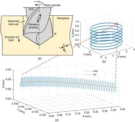
Fig.1 Principles of UAD: (a) macroscopic principle of UAD;(b) macroscopic motion trajectory of points on the cutting edge;(c) microscopic motion trajectory of points on the cutting edge.References to color refer to the online version of this figure
Based on the fundamental principle of UAD,the equations for the motion trajectory of a selected pointPon the cutting edge can be expressed as a parametric equation in terms of relative timet(s),as follows:wheredis the tool diameter (mm),fis the feed rate(mm/r),nis the spindle speed (r/min),andAandFare respectively the vibration amplitude (mm) and frequency (Hz).We selectd=7.5 mm,f=0.05 mm/r,A=0.01 mm,n=1061 r/min (cutting speed of 25 m/min),andF=20000 Hz to obtain the motion track of pointPas shown in Figs.1b and 1c.The parameters used in this modeling are one of the sets of parameters used in subsequent experiments.
In ultrasonic vibration cutting,the tool creates a new path on the cutting surface,which may intersect with the previous path and result in periodic empty cuts,known as the separation characteristic or discontinuous cutting characteristic of ultrasonic vibration machining.This characteristic is also responsible for a range of processing effects in ultrasonic vibration processing.The relationship between the cutting parameters and vibration parameters that generate this separation characteristic is referred to as the separation condition.
According to Sui et al.(2017),the phase difference and the feed amount should meet the following conditions to achieve the separation discontinuous cutting.
whereψis the phase difference.When the phase difference equals π,the separation time in each cycle reaches the maximum,and the best machining effect will be obtained.Calculating the separation condition directly using Eq.(2) is more complex since there are two independent variables: feed rate and phase difference.Therefore,these conditions were decomposed and analyzed,leading to the discovery of different cutting-edge trajectories at various feed rates and phase differences,as depicted in Fig.2.Fig.2a displays the interaction among different cutting-edge paths whenfis less than 4A,whereas Fig.2b represents the critical condition for separation cutting,where different cuttingedge trajectories intersect only at a tangent point,resulting in a cutting thickness of 0.When the phase difference is not appropriate,the situation of nonseparation will occur,as shown in Fig.2c.In Fig.2d,whenfexceeds 4A,there is no intersection point among different cutting-edge tracks,and the cutting thickness is always larger than 0.
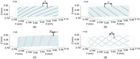
Fig.2 Effect of feed rate and phase difference on cutting-edge trajectory: (a) cutting-edge trajectories intersect,separate type cutting;(b) critical state;(c) cutting-edge trajectories do not intersect,non-separation type cutting;(d) f>4A,non-separation type cutting
When Eq.(2) is satisfied,it signifies that the cutting topography of any cutting tool is formed by the coupling of multiple previous cutting processes,as shown in Fig.3a.Each cutting track intersects with the machined surface,and the minimum cutting thickness is 0,resulting in separated discontinuous cutting and reducing the contact time between the tool and the workpiece.This is a significant reason why UAD offers a range of technological benefits,such as reductions in cutting force and cutting defects.When the feed rate fails to meet these separation conditions,the cutting process is continuous and not separated,as demonstrated in Fig.3b.To date,no researcher has explored the UAD technique with large feed rate and non-separated mode for CFRP/Ti stacks under dry cutting conditions.
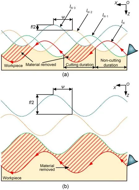
Fig.3 Schematic diagram of material removal in UAD:(a) separation cutting mode;(b) non-separation cutting mode.lN-1 refers to the (N-1)th cutting-edge trajectory
2.1.2 Cutting mechanism of UAD under non-separation conditions
In non-separation UAD,the positive cutting effect induced by separation characteristics no longer occurs.Nevertheless,some other positive cutting effects still exist,such as variable angle cutting and high acceleration cutting.Due to the sinusoidal cutting motion in UAD,the cutting edge has an instantaneous cutting speedvi.Fig.4 illustrates the changing cutting positions in UAD,which cause dynamic change in the cutting angle of the cutting edge.This dynamic cutting angle is beneficial for material removal in the cutting process.
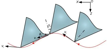
Fig.4 Variable speed and variable angle characteristics of UAD
According to the cutting curve of the UAD,the velocity of the selected pointPin the UAD can be obtained as:
The angle between the cutting speed and thexaxis is:
The instantaneous working rake angleγvcan be expressed as:
whereγis the nominal rake angle of the cutting edge.From Fig.5a and Eq.(5),it can be seen that UAD has a variable rake angle.That is helpful in removing chips,preventing chip accumulation on the front surface that may lead to adhesion wear,and enhancing the cutting performance of the tool.Furthermore,under standard cutting and tool parameters,UAD exhibits a negative cutting zone,which can improve the tool’s durability and prevent possible breakage of the cutting edge.
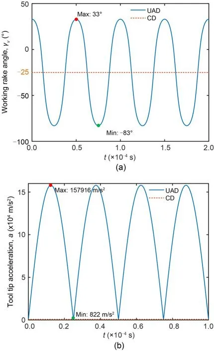
Fig.5 Variable working rake angle (a) and high tool tip acceleration (b)
In this study,the nominal rake angle of the tool is set at -25°.By using MATLAB simulations,we can obtain the varying curve of the tool’s instantaneous working rake angleγvand the cutting acceleration curveafor the tool tip,as illustrated in Fig.5.The parameters employed in this simulation include:d=7.5 mm,A=0.01 mm,n=1061 r/min,andF=20000 Hz.It can be seen from Fig.6a that the vibration in UAD can alter the instantaneous working rake angle,enhancing the tool’s cutting conditions and increasing its material removal capacity.
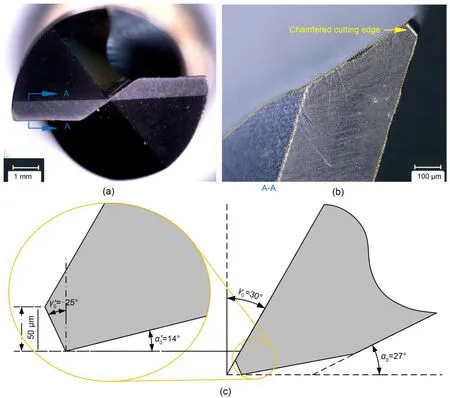
Fig.6 Drilling tool: (a) end surface of twist drill;(b) chamfered cutting edge side view;(c) specific cutting-edge angle
It can be seen from Fig.5b that the value of relative acceleration varies periodically in UAD while the value of relative acceleration in CD remains constant.It should be noted that the maximum tool tip acceleration in UAD is approximately 192 times that in CD (i.e.157916 m/s2vs 822 m/s2).The effect of acceleration in UAD is effective not only in improving the material removal rate but also in preventing chip adhesion in UAD (Geng et al.,2017).The changing acceleration in the feed direction of UAD will provide an impact force when the tool contacts the material,which strengthens the cutting edge’s ability to remove the material and improves the material removal rate in the contact area.
The acceleration of UAD in the feed direction can provide an impact force to the unremoved material,improve the local material removal rate,and increase the cutting ability of the cutting edge.The material that has adhered to the tool can provide an inertial force,and,when that inertial force is larger than the adhesion force,the adhering material is “thrown out”due to it.This effectively reduces the material adhesion phenomenon and prevents severe adhesion wear of the tool.
2.2 Experiments
2.2.1 Properties of workpiece materials and tool
The CFRP used in this test is composed of multiple angles of layup,with a single layer of high-strength unidirectional prepreg measuring 0.125 mm in thickness.The layup direction of multiple layers is [0°/-45°/45°/90°]40,and the material properties of CFRP are detailed in Table 1.The titanium alloy plate used is an annealed Ti6Al4V plate,and its material properties are also shown in Table 1.The material property values in this table are provided directly by the manufacturer Chengdu Aircraft Industrial (Group)Co.,Ltd.(China).The stacking order is the CFRP plate at the top and the titanium alloy plate at the bottom,firmly clamped by a thread connection.This stacking order more closely replicates the formation of stack holes in actual aircraft assembly environments,and to some extent,also inhibits the exit delamination of CFRP.The dimensions of the test pieces were: 200 mm×100 mm×5 mm (CFRP) and 200 mm×100 mm×6 mm (Ti6Al4V).

Table 1 Mechanical properties of titanium alloy and CFRP
The uncoated solid carbide cutting tool used in this test is self-designed and manufactured by Xiamen Jinlu Special Alloy Co.,Ltd.(China).The tool diameter is Φ7.5+0.0030mm.To generate tool resonance in ultrasonic vibration,the length of the tool body is determined to be 55 mm after simulation and vibration adjustment.A 120° positioning taper was used forvibration conduction at the rear end of the threaded handle.The tool featured a negative chamfering blade type,with a 25° negative chamfering anglea 14°flank angleand a 140° top angle.γ0andα0are respectively the second rake angle and the second flank angle.The specific dimensions and angles of the tool are illustrated in Fig.6.The sharpened negative chamfering tool on the edge effectively enhances the tool’s impact resistance (Davoudinejad and Noordin,2014),mitigating issues with cutting edge strength reduction resulting from ultrasonic impact and preventing occurrences of cutting-edge collapse.
2.2.2 Experimental setup and conditions
In this experiment,high-frequency electrical excitation signals from an ultrasonic power supply were transmitted through a conductive slip ring and converted into longitudinal ultrasonic vibration by a BT50 ultrasonic shank.The constitutive structures and modal analysis of the longitudinal vibration transducer used in this experiment are shown in the electronic supplementary materials (ESM).A special fixture was used to clamp the CFRP/Ti stacks workpiece plate and thread was used to connect and press the workpiece.The test platform is shown in Fig.7.
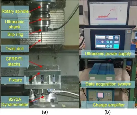
Fig.7 Experimental setup: (a) process part;(b) control part
During the construction of the test platform,the ultrasonic amplitude was adjusted by changing the power of the ultrasonic power supply.The axial ultrasonic amplitude of the tool was measured by a KEYENCE LK-G5000 laser micrometer (China),and for this test,an amplitude of 10 μm was selected.The rotary accuracy of the tool front was measured by a lever micrometer,and the final rotary accuracy was 0.03 mm.In terms of data acquisition,the test platform was equipped with a Kistler 9272A piezoelectric force sensor (Switzerland).The collected charge signal was transformed into cutting force data that can be processed by a computer after passing through the charge amplifier (Kistler 5070A) and the data acquisition system (Kistler 5697A).The sampling frequency was set as 1 kHz in the test.
To verify the separation cutting effect and nonseparation cutting effect of ultrasonic vibration machining,a comparative test was carried out.To prevent thermal damage to CFRP caused by high temperature during dry drilling of titanium alloy,low cutting speeds were selected.The process parameters are presented in Table 2.
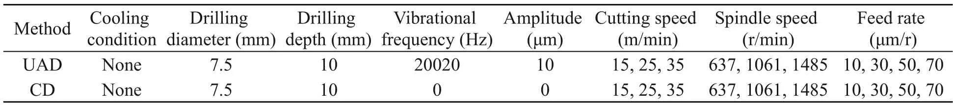
Table 2 Experimental conditions
Moreover,a specific set of test parameters involving non-separation ultrasonic vibration was chosen for the tool wear test.The processing parameters are listed in Table 3.During the test,the wear of the main cutting edge and chisel edge of the tool was observed by microscope at intervals of every five holes,while a total of 60 holes were processed for each set of parameters.

Table 3 Tool wear test parameters
To eliminate any extraneous variables,the same machining parameters were used.The conversion between the UAD and CD is realized by controlling the switch of the ultrasonic power supply.Furthermore,each parameter was replicated twice.To avoid the impact of tool wear,a new tool was employed for each set of parameters.
A three-coordinate measuring system (Aberlink Axiom Too 15097,UK) was employed to measure the drilled hole diameters of the CFRP/Ti stacks,as shown in Fig.8.Each measurement determined the hole diameter value based on eight points at the measurement depth.The measurement was conducted separately for each stacked layer.For each phase,three measurements were performed at different positions,and the average value of these three measurements was used in this study.
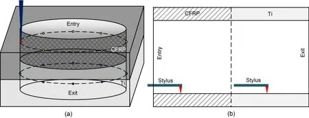
Fig.8 Schematic diagram of the measurement of hole diameters (a) and surface roughness (b)
A surface tester (Talysurf 50,Taylor Hobson,UK) was used to measure the surface roughness of the drilled CFRP/Ti holes.The measurement was made on each material layer.Four measurements were performed with an adjacent angle of 90° along the drilling direction,as shown in Fig.8.The evaluation length and cutoff length were set at 4.0 and 0.8 mm,respectively.In this study,the average value of the four measurements was used to represent the surface roughness of each layer.
3 Results and discussion
3.1 Cutting force
In the experiment,the drilling thrust force (Fz) of stack drilling was measured;the typical curves of the measured force with drilling time in both UAD and CD are shown in Fig.9.It is evident from the figure that the cutting force curves in the two processes follow a similar pattern.The variation of the cutting force can be separated into the following five stages: (I)Entrance drilling stage: the drill bit starts to enter the CFRP panel,and the thrust force gradually rises from zero.(II) Stable CFRP drilling stage: the drill bit completely enters the CFRP panel,resulting in stable thrust force generation.During this stage,the drilling thrust force generated by UAD is approximately 25%lower than that generated by CD.(III) Interface drilling stage: the cutting force increases rapidly when the drill bit drills through the CFRP and penetrates the titanium alloy.In this stage,the cutting force gradually reaches its maximum value.It is noteworthy that,compared to that in CD,the maximum cutting force in UAD is reduced by 22%.Besides,the duration of interface drilling is shortened by ΔTin UAD due to the reduced bending of the titanium alloy panel.(IV) Stable drilling stage of titanium alloy: the drill bit completely enters the titanium alloy,resulting in thrust force generation,due to the ultrasonic vibration that is approximately 21% lower with UAD than that with CD.(V) Exit drilling stage: the bit gradually penetrates and leaves the workpiece,leading to a gradual drop in the cutting force to zero.
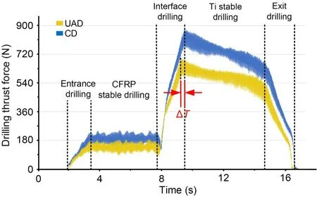
Fig.9 Drilling thrust force curve during CFRP/Ti stacks drilling in both UAD and CD at the cutting speed of 25 m/min and the feed rate of 50 μm/r
Fig.9 demonstrates that CD takes more time during the interface drilling process.With the application of a large thrust force by the drill bit,a bending deformation of the titanium alloy panel occurs,leading to an interface gap and ultimately an extended interface cutting time,as depicted in Fig.10.This unstable bending can result in hole accuracy error and damage.Conversely,UAD significantly reduces the thrust force,leading to a shorter duration of interface drilling.
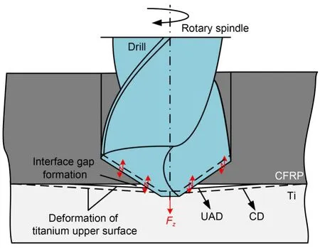
Fig.10 Schematic diagram of interface gap formation in UAD and CD
Fig.11 shows the comparison of the drilling thrust forces under different parameters.The error bars in the figure represent the distribution of data measured three times for each well.The cutting forces in both UAD and CD exhibit the same change trend in which the thrust force increases with the increase of feed and decreases with the increase of cutting speed.As the feed rate increases,the chip thickness and the volume of material removed per tooth increase,resulting in a larger cutting force.With the increase of cutting speed,the friction heat generation between cutting edge and material intensifies,resulting in thermal softening of the titanium alloy and CFRP,which leads to a reduction of the cutting force (Sakurai et al.,1992).Compared to that of CD,the thrust force in UAD of CFRP decreased by 23.3%-30.1%,while the thrust force in UAD of Ti,decreased by 16.7%-23.9%.According to Eq.(2),in this experiment,the required critical feed rate for separation UAD conditions is 40 μm/r.Cutting forces of UAD decrease at low feed rates (feed rate≤30 μm/r) due to the achieved separation cutting mode.At the time of separation,the tool is in a non-cutting state and the cutting force is close to zero,thus reducing the average cutting force during the cycle.
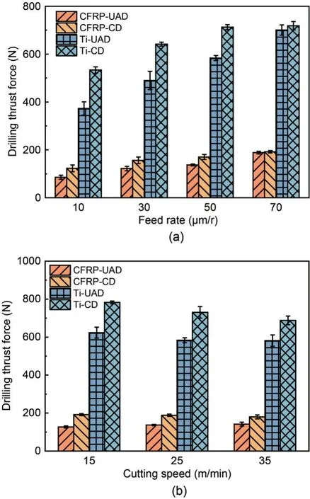
Fig.11 Comparison of drilling thrust forces with different feed rates at the cutting speed of 25 m/min (a) and different cutting speeds at the feed rate of 50 μm/r (b)
When the feed rate is 50 μm/r,the separation effect disappears while the cutting force still decreased by 24.2% for CFRP stage and 22.1% for the Ti stage,respectively.The reasons are as follows: Firstly,in conventional twist drilling,the cutting speed in the middle of the chisel edge is approximately zero,and the material in the middle of the bit is extruded rather than cut.Previous study (Claudin et al.,2008) has shown that the thrust force generated by the transverse edge is up to 50%-70% of the total axial force in drilling.However,in UAD,the material in the middle of the bit is changed from extrusion into impact removal due to the introduction of ultrasonic vibration.Material removal is made easier and therefore the thrust force is reduced.Secondly,the adhesion reduction of the non-separation state of UAD improves the removal ability of microchips and reduces the friction between the tool,the workpiece,and the chips.In addition,due to the ultrasonic vibration,the dynamic working rake angle in the UAD changes with time.During the half vibration cycle of the UAD,the dynamic working rake angle of the cutting edge is larger than that in CD.That is to say,the cutting edge in the UAD is periodically sharper than that in the CD,which facilitates material removal and generates a lower cutting force (Sun et al.,2024).
When the feed rate increases to 70 μm/r,the nonseparation UAD only reduces the cutting forces by 1.9% for CFRP stage and 2.6% for the Ti stage,respectively.Apparently,the force reduction effect of ultrasonic vibration decreases.The reason is that,as the feed rate increases,the thickness of the cutting layer increases and the impact of the bit remains unchanged(the ultrasonic amplitude remains unchanged).At the chisel edge,the proportion of material removed by impact decreases,while the proportion of material removed by extrusion increases,so the effect of force reduction decreases.When the feed rate was increased to 70 μm/r,the ultrasonic vibration still had a force reduction effect of approximately 3%.
3.2 Hole diameter accuracy
Although the drilling is rough machining,the aperture diameter is still an important factor.The closer the hole is to the nominal diameter of the tool,the better for the subsequent reaming process.More precise drilling can effectively reduce the subsequent reaming times.
Fig.12 shows the hole diameter of the measured values under different parameters in an experiment using a three-coordinate measuring instrument to measure the hole diameter.The error bars in the figure represent the distribution of data measured three times for each well.
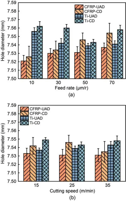
Fig.12 Comparison of the measured diameters of drilled holes with different feed rates at the cutting speed of 25 m/min(a) and different cutting speeds at the feed rate of 50 μm/r (b)
In Fig.12,it can be observed that there is a larger variance in the hole diameter measurement of CFRP.This is primarily due to the presence of voids within the composite material,as well as the surface damage and delamination caused by the drilling process.These factors collectively affect the accuracy of hole diameter measurement and result in a higher variance.As can be seen from Fig.12,compared to CD,the diameter difference in UAD of CFRP decreased by 11.8%-32.6%,while the thrust force in UAD of Ti decreased by 9.3%-32.1%.The results suggest that under different parameters,the UAD has achieved better accuracy,with hole diameters,of both CFRP and titanium alloy,closer to the nominal bit diameter of 7.5 mm.In addition,the feed rate has the greatest influence on the CFRP hole diameter.A slight increase in the feed rate will greatly increase the CFRP hole diameter of CD,but ultrasonic vibration machining greatly reduces this trend.The reasons for the above effects can be summarized as follows: the cutting force reduction effect of UAD during processing effectively reduces the plastic deformation of titanium alloy holes,and at the same time,UAD produces more stable interface drilling during processing,which reduces the radial deviation of the chisel edge when drilling into the titanium panel and avoids bit tilt,thus improving the accuracy of the CFRP holes.
3.3 Hole surface roughness
Fig.13 shows the results of surface roughness of CFRP/Ti stacks holes measured by a surface profilometer.The error bars represent the distribution of data measured at four different locations along the feed direction for each hole.As shown in Fig.13a,when the cutting speed is 25 m/min,the surface roughnesses of both the CFRP phase (Ra∈[1.530 μm,2.066 μm]) and Ti phase (Ra∈[0.141 μm,0.425 μm]),for UAD,were significantly lower than those measured in CFRP phase (Ra∈[2.170 μm,2.467 μm]) and Ti phase (Ra∈[0.456 μm,1.079 μm]),for CD,respectively.It is clear that UAD has an obvious advantage in reduction of surface roughness compared with CD;that is because the cutting force of ultrasonic vibration drilling is reduced and the repeated scraping produced by the bit side edge has the effect of smoothing the hole surface,reducing the non-uniformity of the hole surface and thus reducing its roughness.
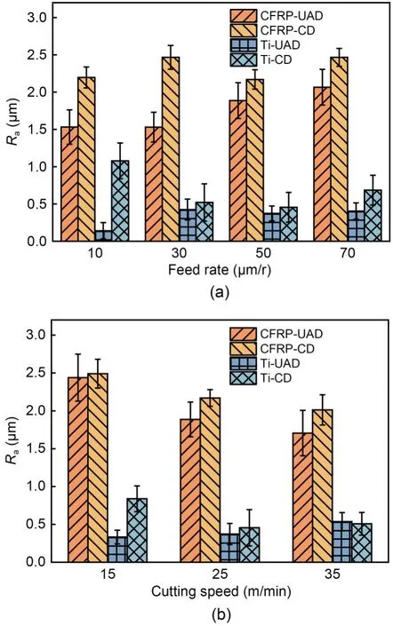
Fig.13 Comparison of roughnesses with different feed rates at the cutting speed of 25 m/min (a) and different cutting speeds at the feed rate of 50 μm/r (b)
3.4 Hole drilling damage
3.4.1 Comparison of CFRP entry-and exit-damage
Delamination is the most undesirable defect in the CFRP drilling process.It is the phenomenon of interlayer debonding of CFRP laminates when the interlayer adhesion strength is not enough to support the drilling thrust force.This generally occurs at the hole exit during drilling (Geng et al.,2019).The mechanical properties of CFRP holes are damaged by large delamination,which seriously affects the assembly performance.The entrance and exit morphologies of CFRP holes in the test are shown in Table S1 of ESM.
The experimental results show that,the entry tearing of UAD has been significantly improved compared with CD,because the dynamic working rake angle of ultrasonic drilling improves the ability of cutting carbon fiber and reduces the occurrence of entry tearing.The lower thrust force of UAD also weakens the peeling effect of surface fibers and the expansion of entry tearing.
In the formation of delamination damage at the exit of the CFRP hole,the cracks that cause drilling delamination can be divided into two types according to the difference between the generated stress: the“opening mode crack” at the exit of holes caused by the axial thrust force of drilling and the “sliding mode crack” at the exit of holes caused by the shear stress caused by material bending (Geng et al.,2019).The hole export layered model,as shown in Fig.14,is mainly caused by the drilling thrust force (Fz) and torque caused by the “opening mode crack” and “sliding mode crack”.The main factor in the production of delamination damage is when the cutting thrust stress is beyond the joint stress among the layers and undermines the resin adhesion between the stacks.Thus,cutting stress in CFRP process control is very important.
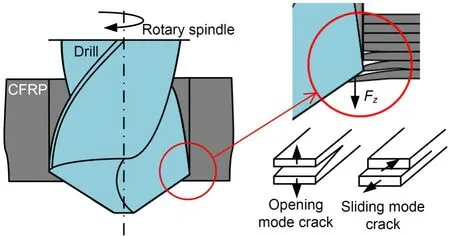
Fig.14 Formation mechanism of hole exit delamination
The exit of the CFRP hole in CFRP/Ti stacks drilling is supported by a titanium alloy,which can effectively suppress the generation of an opening mode crack.Fig.15 shows the specific damage of the hole exit.Compared with CD,UAD reduces the area of delamination and reduces the scope of resin overheat.According to the mechanism analysis in Section 2.1,this is because the intermittent impact characteristic of ultrasonic vibration greatly reduces the drilling thrust force,reduces the opening mode crack generation when the drill bit is drilled,and inhibits the generation of delamination.The reduction in the cutting temperature of UAD plays a role in reducing resin overheat;in addition,the characteristics of UAD increasing the interface drilling stability also reduce the offset of the chisel edge when the drill bit is drilled into titanium alloy and reduce the damage to the CFRP exit.
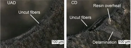
Fig.15 Exit damage of the CFRP holes (at the cutting speed of 25 m/min and the feed rate of 50 μm/r)
To quantitatively analyze the damage,such as resin chlorination,delamination,and tearing at the outlet of CFRP holes,the damage factor is used to evaluate the damage at the exit of these holes by referring to the delamination factor proposed by Chen (1997).The damage factorFdis defined as the ratio of the diameter of the maximum damage position at the exit,Dmax,and the nominal diameter of the hole,Dnom.The damage factor is shown in Fig.16a.To ensure accurate evaluation of damage factors,the edge extraction technology in MATLAB image processing was used to enhance the visibility of damaged edges,particularly highlighting those stratified and torn (Cui et al.,2022).Delamination often exhibits shallow color variation or yellowing,making it crucial for identifying the damaged areas.In this regard,a combination of manual removal of torn hole edges,histogram equalization,and binarization is employed.However,it is important to note that burnt surfaces may appear similar in color to normal surfaces,thus introducing the possibility of identification errors.Nonetheless,the burnt area is typically smaller in size compared to delamination,resulting in a lesser impact on recognizing damage edges.The typical processing results are shown in Fig.16b,where clear delamination and tear damage edges can be observed.After calculation,the damage factor results of CD and UAD are shown in Fig.17.UAD produces small damage factors under various parameter conditions.It is worth mentioning that even in the processing condition under nonseparation UAD,the damage factor was reduced by 6.9% to 9.9%.
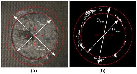
Fig.16 Comparison of damage factors: (a) damage factor schematic original image;(b) edge extraction.References to color refer to the online version of this figure
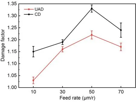
Fig.17 Change of damage factors with the change of feed rate
To study the expansion of delamination inside the hole wall,scanning electron microscope (SEM) images at the exit of the CFRP hole wall are taken as shown in Fig.18.The feed rate is the most sensitive factor affecting delamination.In the case of a large feed rate (Figs.18b and 18d),the delamination at the exit of CFRP is deep,and serious de-adhesion and tearing occur at the hole exit.This is because,as the feed increases,the instantaneous axial impact force in the process of drill bit drilling out CFRP increases,which leads to a larger tearing phenomenon.In addition,ultrasonic drilling has a good inhibitory effect on exit delamination and reduces the depth of the exit delamination in CFRP.According to the previous analysis,this is mainly due to the impact characteristics of ultrasonic drilling which greatly reduce the drilling thrust force and torque,reduce cracks when the drill is withdrawn,and inhibit the generation of the layers.Moreover,ultrasonic drilling can increase the stability of the bit,reduce the bending degree of titanium alloy,and inhibit the formation of CFRP delamination at the interface.
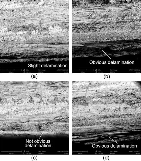
Fig.18 SEM images of hole exit delamination at n=1061 r/min:(a) f=10 μm/r in CD;(b) f=50 μm/r in CD;(c) f=10 μm/r in UAD;(d) f=50 μm/r in UAD
3.4.2 Burr height of titanium alloy
After the test,the burr height at the exit of the hole was measured by ultra depth-of-field microscope.Sample points at four different positions were taken for each hole,and the maximum value of the four measured values was taken to plot the image of burr change with the feed rate,as shown in Fig.19.The increase of feed will also cause the increase of burr height,because the increase of feed leads to an increase in cutting force and cutting heat.In addition,the burr height of UAD was significantly reduced compared with that of CD.Even the non-separation UAD can effectively reduce the delamination at the CFRP hole exit and the burr height by 21.9%-45.2%at the Ti hole exit.This is because the UAD effectively reduces the cutting force and cutting heat and reduces the plastic deformation of the titanium alloy at the exit.
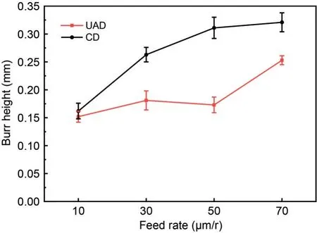
Fig.19 Comparison of burr height with different feed rates at a cutting speed of 25 m/min
3.5 Tool wear mechanism
3.5.1 Mechanism of tool wear of non-separation UAD
In the CFRP/Ti stacks drilling process,due to the relatively low hardness and high chemical activity of titanium alloys,they adhere to the tool during cutting.Meanwhile,the high hardness and wear resistance of CFRP carbon fiber after fracture lead to abrasive wear in the process of CFRP cutting (Xu et al.,2020).Fig.20 shows the SEM microscopic image of tool wear in both CD and UAD at a feed rate of 50 μm/r and a cutting speed of 25 m/min after drilling 60 holes.It can be seen from Fig.20a that the whole main cutting edge of the tool is adhered to by titanium alloy,especially on the outside of the main cutting edge.A large amount of adhered titanium alloy greatly weakens the cutting ability of the cutting edge.In the chisel edge area (Fig.20b),in addition to the severe titanium alloy adhesion phenomenon,abrasive wear can also be observed.Severe wear of the chisel edge weakens the tool’s centering ability,reduces the stability of the drilling process and has a serious impact on the drilling force and hole diameter accuracy.
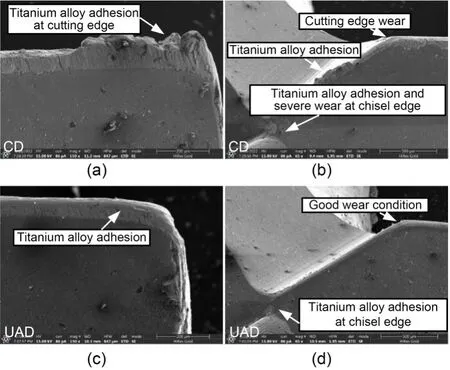
Fig.20 Tool wear after drilling 60 holes of the main cutting edge of CD (a) and UAD (c) and the second cutting edge and the chisel edge of CD (b) and UAD (d)
Figs.20c and 20d show the SEM microscopic image of tool wear in UAD.Compared with that of CD,the titanium alloy adhesion of the cutting edge of the tool is significantly reduced.Also,no bulk adhesion of titanium alloy is found on the outside of the cutting edge of the tool as in CD.This indicates that the adhesion reduction characteristics of hysteretic separation UAD play a significant role in adhesion wear.At the chisel edge,the wear of the cutting edge of the tool is much lower than that of CD (Figs.20b and 20d).The titanium alloy adhesion on the chisel edge is also significantly reduced,and the wear of the chisel edge is significantly improved,compared with CD.This indicates that the chisel edge in UAD still has good material breaking and centering ability after drilling 60 holes.
3.5.2 Wear evolution process
To study the evolution of tool wear,the cutting edge was photographed every 10 holes,and the results are shown in Table S2 of the ESM.The adhesion reduction characteristics of non-separation ultrasonic vibration effectively weaken the adhesion of titanium alloy,throwing away the adhered titanium alloy debris on the surface and reducing the adhesion wear of titanium alloy to the tool.Moreover,the side edge of UAD repeatedly scratches the surface of the hole wall in the process,which also reduces the accumulation of adhering amounts of titanium alloy on the outside of the cutting edge.
4 Conclusions
In this study,experimental ultrasonic vibration dry drilling of CFRP/Ti stacks is carried out,and the machining effect of two modes of ultrasonic vibration drilling under different machining parameters is analyzed.In addition,the tool wear test of non-separation ultrasonic vibration drilling is also carried out.The following conclusions are reached:
1.Compared to conventional separation UAD,the non-separation UAD still effectively reduces the cutting forces by 24.2% and 1.9% for CFRP stage and 22.1% and 2.6% for the Ti stage at the feed rates of 50 and 70 μm/r,respectively.
2.The non-separation UAD can significantly improve the hole diameter accuracy (11.8%-32.6% for CFRP and 9.3%-32.1% for Ti) and reduce the surface roughness (14.8%-19.3% for CFRP and 22.0%-40.1%for Ti).
3.The non-separation UAD can effectively reduce the delamination at the CFRP hole exit and the burr height by 21.9%-45.2% at the Ti hole exit.
4.The non-separation type UAD can reduce the adhesion of titanium alloy to the cutting tool due to its adhesion reduction characteristics.
Acknowledgments
This work is supported by the National Natural Science Foundation of China (Nos.52375399 and 91960203) and the Aeronautical Science Foundation of China (No.2022Z045051001).
Author contributions
Zehua ZHOU and Zhenyu SHAO designed the research.Zhefei SUN,Lianxin LIU,and Yihang LIU processed the corresponding data.Enze YING wrote the first draft of the manuscript.Daxi GENG,Xinggang JIANG,and Deyuan ZHANG helped to organize the manuscript.Enze YING revised and edited the final version.
Conflict of interest
Enze YING,Zehua ZHOU,Daxi GENG,Zhenyu SHAO,Zhefei SUN,Yihang LIU,Lianxing LIU,Xinggang JIANG,and Deyuan ZHANG declare that they have no conflict of interest.
 Journal of Zhejiang University-Science A(Applied Physics & Engineering)2024年4期
- Journal of Zhejiang University-Science A(Applied Physics & Engineering)的其它文章
- Influence of overhanging tool length and vibrator material on electromechanical impedance and amplitude prediction in ultrasonic spindle vibrator
- Prediction of undeformed chip thickness distribution and surface roughness in ultrasonic vibration grinding of inner hole of bearings
- Influence of vibration on the lubrication effect of a splash-lubricated gearbox
- N-doping offering higher photodegradation performance of dissolved black carbon for organic pollutants: experimental and theoretical studies