Research on the influences of motion characteristics of jetting projectile charge under water
Xing Chen, Yong-gang Lu
Institute of Systems Engineering, China Academy of Engineering Physics, Mianyang 621900, Sichuan, China
Keywords:JPC Movement characteristics Underwater penetration Numerical simulation
ABSTRACT Shaped charge warhead is important for enhancing the damage performance of underwater weapons.This paper used finite element analysis software and based on JPC water penetration experiments to examine the influence of liner parameters (wall thickness, material), charge aspect ratio, and stand-off distance on the movement characteristics of JPC in water.The findings reveal that the head diameter of the JPC increases and experiences significant erosion after entering the water, the effective length of the JPC in water undergoes two distinct phases:a growth phase and a decrease phase, with the velocity of the JPC decaying exponentially.Increasing the liner thickness,stand-off distance and the charge aspect ratio can improve the erosion resistance and the velocity retention capacity of the JPC.The optimal ranges for liner thickness and stand-off distance are 0.0363Dk to 0.0545Dk (Dk is the charge diameter),the stand-off distance should be within 1.0Dk.After the charge aspect ratio higher than 1.25, the charge structure exerts minimal influence the movement characteristics of the JPC in water.Material density plays a crucial role in the velocity decay pattern of the JPC during penetration.JPC with higher densities exhibit superior velocity retention capabilities in water,with the velocity decay pattern converging if the densities are similar.Consequently, copper, tantalum and tungsten liners are deemed appropriate for underwater shaped charge warhead.Finally, the results will provide an important reference for the design of underwater shaped charge warhead.
1.Introduction
In order to enhance the ship’s protection, high-strength steel materials are utilized,while on the other hand,a multi-layer plate and frame protection structure is employed in the form of an"empty cabin-liquid cabin-empty cabin"combination.This design ensures that the extent of damage caused by underwater weapon attacks on the ship remains within acceptable limits.By improving the ship’s protection level, traditional charge warheads now face significant challenges.Nonetheless, the high-speed metal jets a shaped charge warhead produces have a significantly higher energy density than a shock wave.These jets not only have the potential to puncture the ship’s hull structure but can also damage the equipment and internal structures within the ship.Hence, the shaped charge warheads present a novel approach to achieving efficient damage for underwater weapons.
By adjusting the design of the liner, various penetrator morphologies and velocities can be achieved,such as the shaped charge jet (JET), the explosive formed projectile (EFP), and the jetting projectile charge (JPC).Researchers have conducted comparative studies on the underwater penetration performance of these three types of penetrators[1-4].The results indicate that the JET has the highest velocity,but its speed decays the fast experiment in water.The large velocity gradient tends to fragment the jet, forming multiple penetrators and resulting in less efficient use of the liner[5,6].While the EFP has a smaller velocity gradient and does not stretch or break during the water penetration process, its larger diameter causes the penetrator to greater resistance.This leads to deformation and breakage of the penetrator’s head, as well as a significant reduction in mass, causing it to lose its damaging capability after traversing a distance of approximately 5Dk-6Dk(Dkis the charge diameter)in water[7,8].The velocity and morphology of JPC are between those of JET and EFP, moreover, the JPC has greater resistance to interference and mass dissipation than JET,and higher velocity and storage capacity than EFP.During underwater penetration, the JPC can produce a cavity-following effect,allowing subsequent penetrators to enter without loss.This makes the JPC particularly suitable for penetrating multi-layered structures containing water[9,10].This finding is supported by the study conducted by Wang[11,12],their research results demonstrate that under the same charge equivalent conditions, the blasting type charge only caused a perforation in the empty compartment of the mine protection structure.In contrast, the JPC formed by the shaped charge warhead can cause perforations with diameters ranging from 1/3Dkto 1/2Dkin both the front and rear panels of the liquid compartment within the mine protection structure.This suggests that researching the underwater penetration performance of JPCs is not only scientifically significant but also holds considerable engineering value.
The damage capability of the jet relies on the penetrator’s velocity and morphology, with the liner structure and charge being the primary influencing factors.Ma [13] used LS-DYNA to numerically simulate the forming process of LEFP, and the influence of initiation method, the length of shell platform, the radius of curvature and the thickness of the liner on the forming of LEFP were analyzed.Moreover, an optimization scheme was designed to optimize the geometric parameters of the shaped charge to improve the penetration ability of LEFP.Zhu[14]used AUTODYN to study the residual microstructure characteristics and geometric parameters of EFP formed by liner in different materials.They found that tantalum material is more conducive to the formation of EFP.Hu[15,16]and Zaki[17]investigated the influence of different explosive materials and liner shapes on the penetration ability of EFP,and obtained the best combination of liner and explosive.Yang[18] and colleagues conducted X-ray experiments and static penetration experiments on the formation of JPC to study the impact of variable wall thickness methods for the liner on the forming morphology and penetration capability of the JPC.The results reveal that a liner with a thick top and mouth and thin middle configuration is the most effective, increasing the JPC quality by 22% and the head velocity by 10% compared to the traditional single liner.Yang[19]investigated a sensitivity analysis of liner wall thickness,charge height,and detonation radius for JPC forming parameters using LS-DYNA finite element analysis software and the orthogonal experiment method.They focused on the equal-wall-thickness hemispherical liner structure and determined the sensitivity of these three influential factors on the evaluation index.Xu [20] proposed a new high-speed JPC shaped charge structure.They examined the effect of the cut-off top height of the liner’s add-on device on JPC formation through a combination of numerical simulation and experimentation.Ultimately, they optimized the shaped charge structure to achieve high jet velocity and minimal velocity gradients.
The studies mentioned above mainly concentrate on the formation of jet in the air.However, a number of researchers have expanded their focus to investigate the damage mechanisms of JPCs on underwater targets as well.Li [21] used the coupled SPH-FEM algorithm to simulate the damage mechanism of a shaped charge warhead on a double-layered cylindrical shell structure.Their findings revealed that the strong penetration of the metal jet resulted in a small and localized penetration of the structure.Additionally, under the combined effects of shock wave loads and bubble loads, the structure experienced large area breakages and plastic deformations.Chen[22,23]analyzed the influences of liner structure parameters on JPC formation and underwater damage capability, obtained the optimal parameter range for the liner structure and discovered that high-density tungsten and tantalum liners have potential applications in underwater shaped charge warheads.Meanwhile, in a study conducted by Wang [24], it was demonstrated that material density significantly impacts the velocity retention capacity of the penetrators in water.Higher density penetrators exhibit stronger velocity retention capacity, while penetrators with similar densities display comparable velocity decay patterns.
The aforementioned study is based on a single liner structure,which produces only one penetrator, an alternative design idea involves utilizing a double liner structure.The goal is to generate more than two segments of penetrators, with the forward penetrators creating a transient cavity in the water.This provides a channel for the subsequent penetrators without energy consumption, thereby enhancing the effectiveness of the following penetrators in damaging underwater targets[2].Zhou[25],Zhang[26],and Jiang[27]introduced a sub-liner at the top of a hemispherical liner to form the forward JPC.the research demonstrated that the subsequent JPC’s movement within the cavity created by the forward JPC can reduce the loss of kinetic energy.Additionally,using a sub-liner made of low-density materials can result in a JPC with distinct front and rear sections.This configuration has a notably better damage capability compared to a JPC formed by traditional single liners and single-material combination liners.
In summary,current research findings provide some insight into the JPC water penetration mechanism.These studies show that the water travel and penetration capability of the JPC is related to a variety of factors,such as the speed,morphology and quality of the JPC,which in turn are directly related to the parameters of the liner structure and charge structure.However, there are still considerable challenges to create JPC with efficient damage capability after the detonation of a shaped charge warhead.Therefore,the present paper integrates existing research results derived from JPC water penetration experiments and finite element analysis software.The study analyzes the impact of liner wall thickness, liner material,charge aspect ratio, and stand-off distance on the movement characteristics of JPC in water.The research findings will serve as an important reference for the design of underwater shaped charge warhead.
2.Numerical simulation and experiment of JPC underwater penetration capability
2.1.The structure of warhead
In this paper,the formation of JPC and the movement properties in water were investigated.A warhead was designed and structured as shown in Fig.1.The warhead consists of three parts:liner,charge,and shell.The charge is GO-2,with a diameter(Dk)of 11 cm and a height (H) of 8.8 cm.The shell is made of 2A12 aluminum with a thickness of 0.5 cm.The liner is a cone-arc bonded type with equal wall thickness and made of copper, as shown in Fig.2.The liner thickness(T)is 0.44 cm,the circle radius(R)is 4.4 cm,and the cone angle(α)is 130°.The point of detonation is located at the center of the charge’s tail.
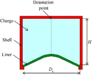
Fig.1.Structural diagram of shaped charge warhead.

Fig.2.Structure and parameters of ace-cone liner.
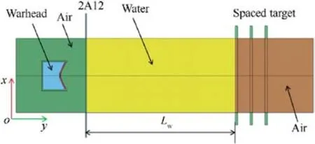
Fig.3.Numerical simulation model of JPC penetration water.
2.2.Numerical simulation model
In this study,The numerical simulation model was simulated by finite element analysis software, as shown in Fig.3.The numerical simulation model consists of five parts:shell,charge,liner,air,water,2A12 aluminum plate and target plate.A 2D-axisymmetric model(with respect to the Y-axis) was employed to minimize computational cost.The numerical algorithm applied was Fluid-Structure Interaction (FSI), where the shell and target plates were represented by Lagrangian grids, while the charge, air, water, and liner were depicted using Euler grids, and coupling the Lagrangian and Eulerian grids using the *CONSTRAINED_LAGRANGE_IN_SOLID,Furthermore, non-reflective boundary conditions were implemented at the air and water boundaries,effectively preventing shock wave reflections at these interfaces.The model was constructed using the g-cm-μs unit system.According to the study of mesh convergence,the numerical simulation results have converged when the mesh size is 0.1 cm, therefore, the mesh size in the numerical simulation is 0.1 cm×0.1 cm[23].It should be specified in advance that the numerical simulation model does not include 2A12 aluminum plate and target plates when investigating the effect of factors on the JPC’s water penetration characteristics.
2.3.Material model and parameters
In this study, GO-2 high energy charge is used as the main charge of the shaped charge warhead.High-energy material model and JWL equation of state are adopted in simulation,JWL equation of state is used to accurately describe the pressure, volume and energy features of explosive gaseous product in the process of explosive driving.In which the pressure p is expressed as
where A1,B1,R1,R2and ω are parameters related to the charge.V is the specific volume.E is the specific internal energy.The parameters of GO-2 are listed in Table 1 [23].
The MAT_NULL model and the Gruneisen equation of state are used to describe water in the paper.Air is described by the MAT_NULL material model and the Linear Polynomial equation of state,where the pressure of the linear polynomial equation of state is defined by Eq.(2).
where:C0-C6are constants;μ=1/V-1,μ is the relative volume;E is the initial internal energy per unit volume.When C0= C1= C2=C3=C6=0 and C4=C5=γ-1,the air is described by a gas model that agrees with the γ-law equation of state, and γ is the specific heat coefficient.The main material parameters are shown in Table 2[22].
The materials of metals are described by the Johnson-Cook in the paper, which expressed the behavior of materials subjected to high strains, high strain rates and high temperatures.The yield stress σyis defined as
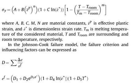
where D1-D5are the material parameters and σ*is effective stress.The material failure occurs when D = 1.0.In the numerical simulation, the material of the target is 45# steel with Lagrange’s algorithm, D1=0.8, D2-D5is 0, and the other metal materials with D1-D5are 0.To describe the material at a high strain rate, the equation of state of Gruneisen is used,the pressure p is defined as
where ρ0is the initial density.C is the intercept of the vs-vpcurve.S1, S2and S3are the coefficients of the slope of the vs-vpcurvewhere vsand vpare shock-velocity and particle-velocity, respectively.γ0is the unitless Gruneisen gamma.The first order volume correction for γ0is a.And μ=ρ/ρ0-1.E represents internal energy.The parameters of metals are listed in Table 3 [22].

Table 1 Material parameters of charges.

Table 2 Material parameters of air and water.
2.4.The penetration experiment of JPC underwater
2.4.1.Experiment setup
Fig.4 presents the layout of the experiment setup.The warhead,as shown in Fig.5, is positioned on a "V"-shaped wooden support frame and aligned with the centerline of the tank.The front panel of the water tank is composed of an aluminum alloy(2A12)plate with a thickness of 0.3 cm, and the stand-off distance is 8 cm.The warhead’s head face is parallel to the tank’s front plate, ensuring that the JPC penetrates the tank vertically.The targets illustrated in Fig.6,consist of three-layer spaced targets,each having dimensions of 40 cm×40 cm×1 cm and constructed from 45#steel,and fixing the spaced targets to the triangular supports.Two experiments were conducted,with water layer thicknesses of 60 cm and 100 cm,respectively.The research focuses on the laws of morphology and velocity changes during the movement of JPC in water.In the real condition JPC is not disturbed by water during the forming phase,so the warhead is arranged in the air which makes JPC formed and then penetrates water.
2.4.2.Experiment results and analysis
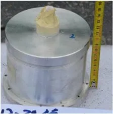
Fig.5.The experiment warhead.

Fig.6.The spaced target.
Fig.7 displays the target damage results obtained from the experiments.When the water layer thickness is 60 cm, the target plate’s damage mode is perforation, with perforation diameters measuring 6.5 cm, 6.2 cm, and 4.96 cm, respectively.Conversely,when the water layer thickness is 100 cm, the first layer of targets exhibits a penetration cavity with an approximate diameter of 4.5 cm, while the maximum deformation of the first and second target plate layers amounts to 7.5 cm and 2.3 cm, respectively.
Numerical calculations performed for the experiment utilizingthe numerical simulation method presented in this study.The findings indicate that the target damage results are in agreement with the experiment outcomes, as depicted in Fig.8.Fig.8 shows the comparison of the target plate profile, it can be seen that the damage model of the spaced target matches the test results and the test value of the deformation in the central region of the target plate is higher than the numerically calculated value.The error between the numerical calculation and the test is within 16.1%, as demonstrated in Table 4.The reasons for the error could be related to the target fixation method and the damage parameters measurement technique.In numerical simulations,the target perimeter is subject to fixed constraints, while in experimental conditions, it is not feasible to achieve a fully constrained target.Furthermore,the numerical model is inherently two-dimensional, allowing for the measurement of only the maximum perforation diameter and target plate deformation.In contrast,experimental target plates are three-dimensional, necessitating multiple measurements of the perforation diameter and target plate deformation,which are then averaged for analysis.In addition, the verification of the penetration behavior of EFP in water was added with reference to the tests in the literature(due to the limitations of the test conditions, data on the penetration behavior of JPC in water was not obtained).The results of the calculations are shown in Fig.9(a)shows the change in the morphology of the air cavity and Fig.9(b) shows the displacement curve, which was compared with the experimental data and the calculation error is within 11%.Eventually,the error is controlled within 20%, which indicates that the numerical calculation results in this paper have certain accuracy and the calculation results meet the requirements of engineering design.

Table 3 Material parameters of metals.

Fig.4.Schematic diagram of the experiment setup and principle of JPC penetration water: (a) Image of the experiment setup; (b) Schematic diagram of the experiment.

Fig.7.Target damage results of the experiment: (a) Water layer thickness is 60 cm; (b) Water layer thickness is 100 cm.

Table 4 Comparison of experiment and simulation results.
2.5.Characterization of JPC movement in water
2.5.1.The process of JPC penetration into water
As the JPC progresses through the water, it persistently evacuates the fluid surrounding its head,inducing a circumferential flow in the direction of incidence, which ultimately results in the formation of a near-conical cavity, causing only its head to make contact with the water.The pressure cloud representation of the cavity formation process is depicted in Fig.10.It is evident that the jet continuously transfers kinetic energy to the water as it traverses,consequently promoting the expansion of the air cavity.Furthermore, during the penetration process, the deceleration of the JPC results in the cavity expanding laterally at a higher rate in the initial stages compared to the later stages.Throughout the entire penetration process of the water,a local high-pressure zone consistently exists at the JPC’s head,where the peak pressure,measured in GPa,substantially surpasses the strength of the jet material,which is in the MPa range.

Fig.8.Comparison of experiment and simulation of target plate damage results: (a) Water layer thickness is 60 cm; (b) Water layer thickness is 100 cm.
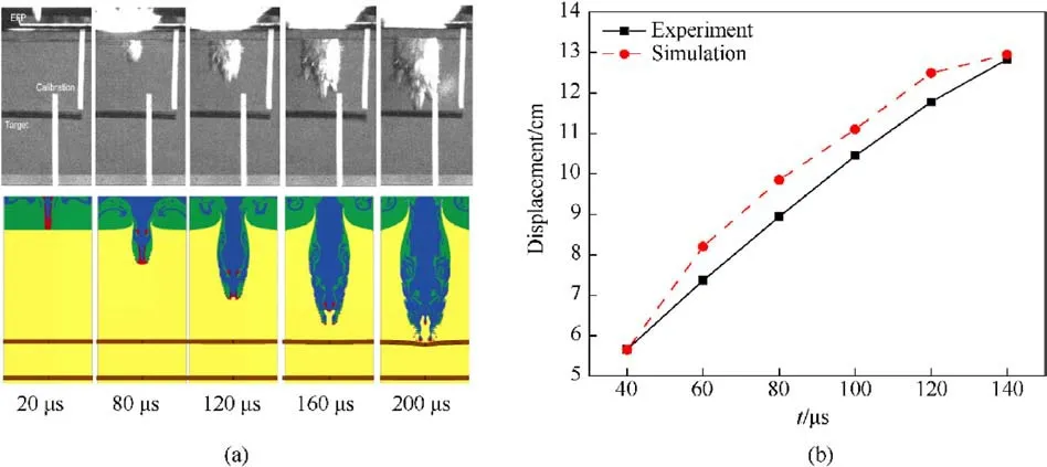
Fig.9.Verification of EFP penetration behavior in water: (a) Images of the EFP penetration process in water; (b) Comparison of penetration distance in water.
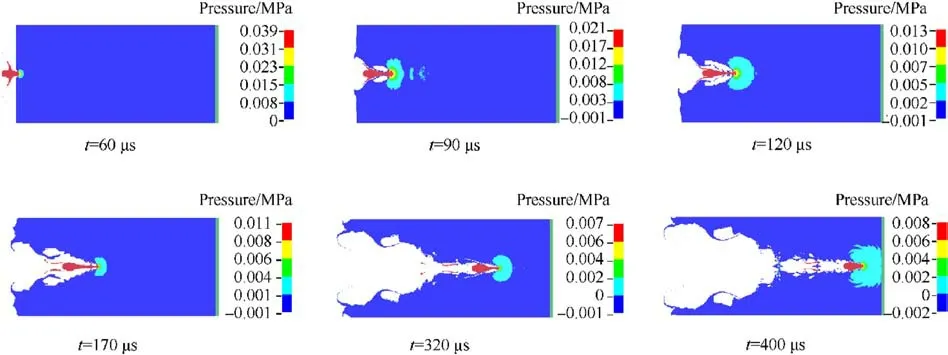
Fig.10.The process of JPC penetration water.
2.5.2.The rule of the morphological variation
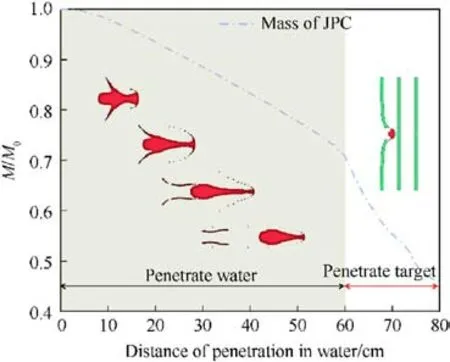
Fig.11.Relationship between the relative mass of JPC and penetration distance.
With the JPC penetration,a localized high pressure develops in its head region,with the pressure value significantly exceeding the yield strength of the JPC’s material.Consequently, the diameter of the JPC head increases,leading to mass erosion as it penetrates the water.The variation of relative mass with penetration distance is shown in Fig.11.Where M is the residual mass of the JPC and M0is the initial mass of the JPC at the moment of entry into the water.As can be seen from the figure, the mass of the JPC decreases approximately linearly,except that the slope of the decrease in the water penetration phase is lower than that of the target plate penetration phase.
Here the effective length is defined,denoted by the symbol"Lx"",representing the effective length between the head and tail of the JPC,so when the JPC is fractured,the fracture interval is not counted in the value of the effective length.Fig.12 illustrates the variation in the JPC’s effective length with respect to the penetration distance.The figure also shows the variation of the effective length in the air with penetration distance,which shows that the effective length in air increases approximately linearly, while in water the effective length first increases and then decreases.The main reason is that water is an incompressible fluid with a much higher kinetic and kinematic viscosity than air, so the JPC undergoes significant erosion and deformation when penetrating water.Upon entering the water, the JPC’s effective length initially increases before eventually decreasing.In the growth phase,the JPC stretches due to the velocity gradient in the water,causing its length to increase.The rate of increase in the JPC’s length surpasses the head erosion rate during this phase, resulting in a near-linear increase in effective length with distance.Conversely, when the rate of increase in the JPC’s length falls below the erosion rate, the effective length gradually decreases.
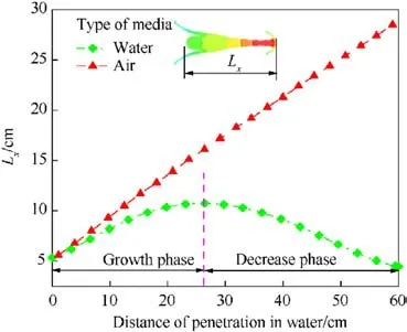
Fig.12.Variation of JPC effective length with distance.
2.5.3.The rule of variation of velocity
The velocity of the JPC experiences a gradual decrease as it moves through the water, primarily due to the resistance exerted by the water.A theoretical derivation of the decay equation for the overall velocity of the JPC can be established by applying Newton’s second law and the momentum equation.
Assuming that the resistance to the front of the rod is F,it follows from Newton’s second law that
where M is the mass of the rod and vxis the average velocity of the rod.
From the momentum equation, it follows that
where m is the mass of the water medium acting on the head of the rod in time dt.
Assuming that there is a linear relationship between the rod length (L) and the distance of movement(x).
Then, the mass of the rod is as follows:
where ρMis the rod density,ρwis the density of the water,L0is the initial length of the rod,Sxis the cross-sectional area of the rod and S0is the initial cross-sectional area of the rod.
The head of the rod is subjected to the impact of water,assuming a linear relationship between its cross-sectional area(Sx)and the distance (x).
Then, there is the following derivation process:
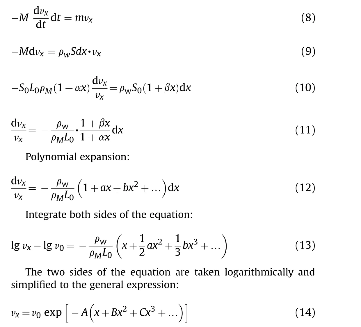
where v0is the initial velocity of the rod,A、B and C are the fitting coefficients, the magnitudes of coefficients B and C are 10-5and 10-8[24].It can be seen that the influence of these two items on the results is small.Therefore,Eq.(14)retains only the primary term of x to ensure the required accuracy of the fit, and the formulation is simplified as follows:
where K is the velocity decay coefficient.
Fig.13 displays the velocity of the JPC as a function of penetration distance,which is employed to examine the velocity variation of the JPC.The JPC’s velocity decay occurs more rapidly until the penetration distance is less than 40 cm; however, once the penetration distance surpasses 40 cm, the rate of velocity decay gradually diminishes.When the penetration distance is under 40 cm,the JPC’s rod contacts the water, and its velocity ranges from approximately 1 km/s to 3.5 km/s.The higher velocity heightens the water’s resistance to the JPC, causing the velocity to decrease more swiftly.Conversely, when the penetration distance exceeds 40 cm,the rod is almost entirely eroded,leaving the pestle body to interact with the water at a velocity lower than 1 km/s.The reduced penetrator velocity, as well as the decreased water resistance,contribute to a slower decline in the JPC’s velocity.By applying Eq.(15) to fit the data, the velocity decay coefficient K of the JPC in water was determined to be 1.0573.
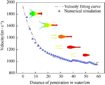
Fig.13.Fitting curve for velocity with penetration distance in water.
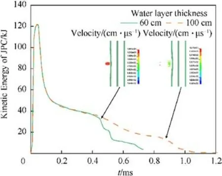
Fig.14.Comparison of kinetic energy of JPC with different Lw.
Therefore, the velocity decay coefficient (K) is used in the next study to measure the velocity decay characteristics of the jet in water.The value of K is smaller,the velocity of the jet decays more slowly in the water and the velocity storage capacity is better; on the contrary,the value of K is larger,the velocity storage capacity of the JPC is weaker.
2.5.4.The rule of variation of kinetic energy
Apart from the water layer thickness,the experiment conditions remained consistent between the two experiments.The variation of the kinetic energy of the JPC with time for the two experiments was obtained by numerical simulation and is shown in Fig.14.It can be seen that when the water layer thickness is 60 cm, the kinetic energy when JPC penetrates the target plate is 32.5 kJ; and when the water layer thickness is 100 cm, the kinetic energy when JPC penetrates the target plate is 11.1 kJ.The kinetic energy decayed by 65.8% at a rate of 53.5 kJ/m.The experiment results reveal that water possesses a significant capacity to attenuate the JPC’s kinetic energy, which directly impacts its damage potential.
3.Numerical simulation on the motion characteristics of JPC
Generally,the liner and charge parameters directly influence the JPC’s formation, which subsequently affects its movement characteristics in water.Hence, this paper examines the effects of liner wall thickness, liner material, charge aspect ratio, and stand-off distance on the JPC’s movement in water.It also analyzes the variations in formation,effective length,and velocity decay of the JPC within a water environment.A detailed numerical calculation scheme for this investigation is presented in Table 5.
3.1.Influences of the liner thickness
Without altering the liner’s configuration and the charge’s structure,the liner thickness is varied between 2 mm and 6 mm(in increments of 1 mm).Table 6 presents the molding effects of the JPC for different liner thicknesses.The calculation results reveal that the liner thickness significantly impacts the JPC’s morphology.With T=2 mm and 3 mm,the rod diameter is small.Furthermore,at T=2 mm,the JPC lacks a distinct pestle structure,and the entire JPC structure experiences "necking" in multiple locations during movement, ultimately fracturing into several penetrations.At T = 4 mm, 5 mm, and 6 mm, the JPC exhibits a thicker structure,with "necking" occurring at the joint between the rod and pestle.The dense spherical structure of the JPC’s pestle ensures that,after the rod is fully eroded, the remaining penetrators maintain sufficient damaging capability.As shown in Fig.15,the effective length value increases with the liner’s wall thickness during the growth phase,but the increase stabilizes when the wall thickness exceeds 4 mm.The effective length value gradually increases as the wall thickness rises from 2 mm to 4 mm during the decrease phase,and the effective length value progressively decreases as the wall thickness continues to increase.
Fig.16 shows the decay relationship of the relative mass of JPC.According to the figure,as the thickness of the liner is smaller,the mass loss of JPC is faster, and when the thickness of the liner is 4-6 mm,the mass loss rate of JPC is approaching.The reason is that as the thickness of the liner increases,the higher the proportion of mass accounted for by the JPC pestle (As shown in Table 6),therefore,increasing the wall thickness of the pharmacophore can reduce the mass loss of JPC.
When the shape of the liner is kept constant, the ability of the liner to convert blast energy is constrained, meaning that increasing the thickness of the liner from 2 mm to 6 mm will gradually increase its mass and decrease the blast energy obtained per unit mass of the liner.Consequently, the initial velocity of the JPC is reduced by 1.6 km/s from 3.2 km/s, and the velocity decay coefficient is decreased from 2.86 to 0.95, representing a 66.8%decrease, as illustrated in Fig.17.Although increasing the wall thickness of the liner significantly impacts the initial velocity and velocity decay coefficient of the JPC, the velocity of the residual penetrators gradually converges and stabilizes between 750 m/s and 850 m/s once the JPC reaches a distance of 60 cm (5.5Dk) in water.
Overall, increasing the thickness of the liner can enhance the erosion resistance and velocity storage performance of JPC in water,and JPC with a thickness in the range of 0.0363Dk-0.0545Dk(4-6 mm)exhibit excellent underwater movement characteristics,with a good balance between erosion resistance and velocity storage performance.
3.2.Influences of the liner’s materials
To form a penetrator with excellent penetration properties,the material used for the liner must possess certain properties,such asplasticity, high density, high melting point, and appropriate strength.The plasticity ensures that the jet is resistant to breakage during stretching,while the high density provides the jet with high specific kinetic energy at the same velocity, and the high melting point prevents the liner from vaporizing during the formation of the jet.In this study, seven materials were selected for the liner,including aluminum, iron, soft steel (10# steel, 20# steel), copper,tantalum, and tungsten, to investigate the effect of different densities or the same densities of materials on the movement characteristics of the JPC in water.

Table 5 Numerical calculation schemes.
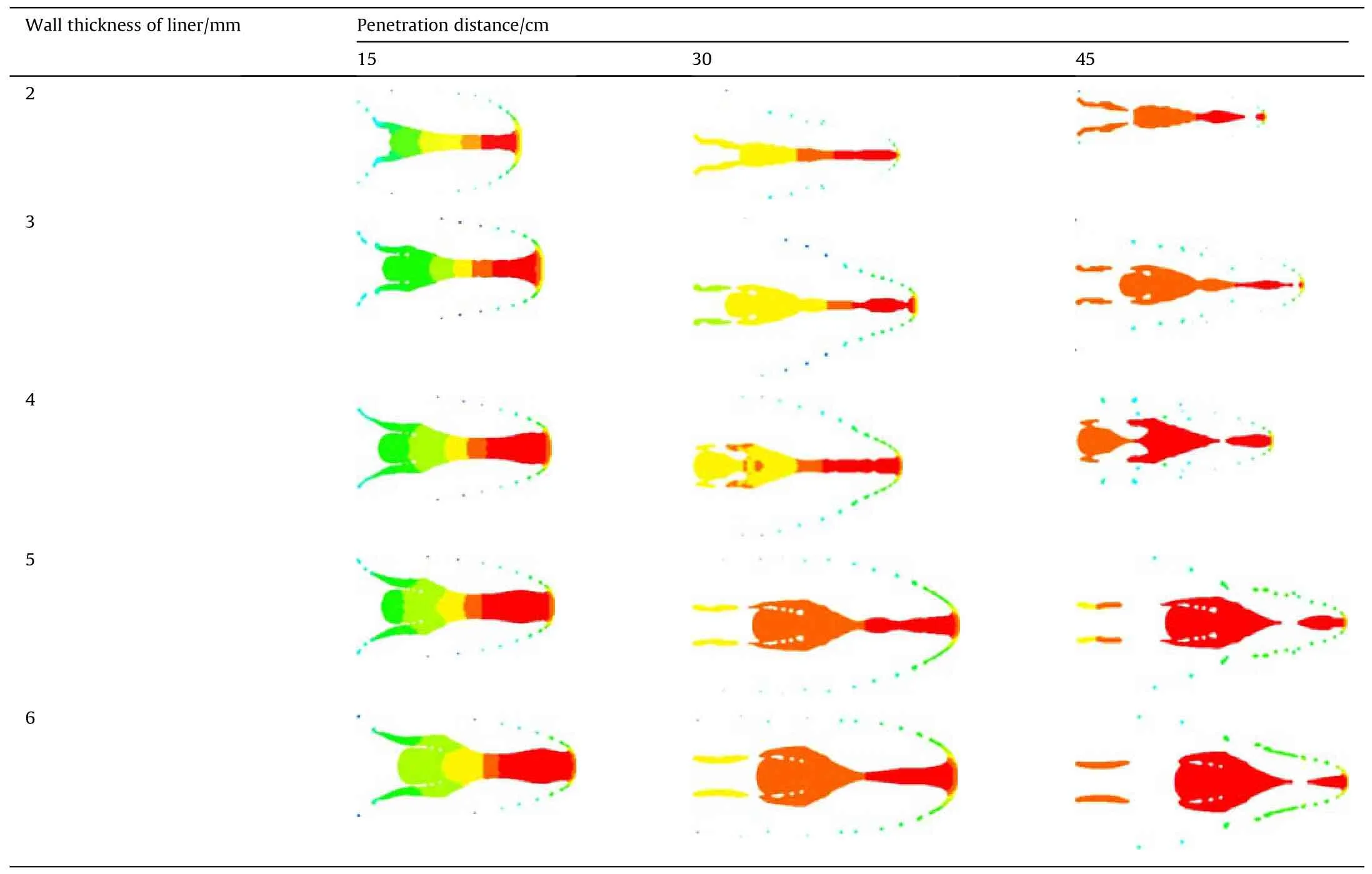
Table 6 Morphological changes of JPC in water under different wall thickness.
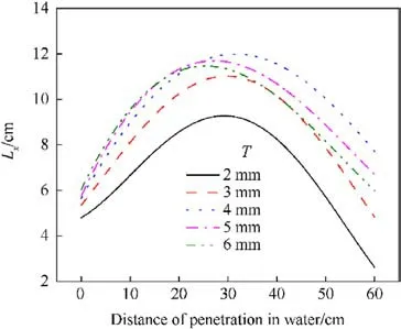
Fig.15.Variation of the effective length with the wall thickness of liner.
Table 7 presents the morphological changes of the JPC in flight in water.The results indicate that the JPC formed by the aluminum liner has the worst morphology,with a hollow structure at the tail,and is highly susceptible to mass erosion during flight in the water.It is completely eroded and loses damage potential after 25 cm(0.25Dk)of flight in the water.The tungsten liner forms an EFP with a relatively small aspect ratio and a large diameter tail skirt structure, while all other materials are capable of forming a slim structured JPC.Moreover, iron,10# steel, and 20# steel have the same density, while the strength of the materials increases gradually.Comparing the results of JPC formation shows that the degree of stretching of the JPC decreases with increasing strength(as shown in Fig.18),this indicates that the strength of the material affects the degree of stretching of the JPC in water.
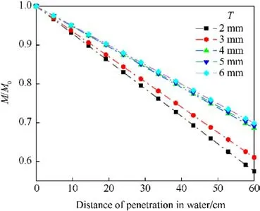
Fig.16.Relative mass with the wall thickness of liner.
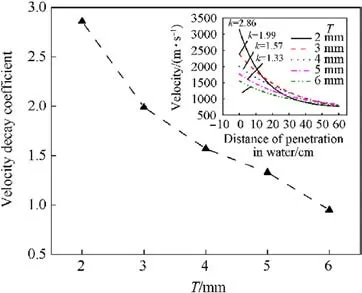
Fig.17.Variation of velocity and decay coefficients with the wall thickness of liner.
Fig.18 illustrates the variation of the effective length of the jets with distance for different materials.The effective length of the JPC composed of tantalum demonstrates the highest value throughout the water penetration process, followed by iron and copper.The remaining materials of JPC exhibit poor effective length.As can be seen from Fig.19, the mass loss rate is arranged from smallest to largest following the order of tantalum,tungsten,pure iron,purple copper,10#steel,20#steel,aluminum,which shows that the mass loss rate of JPC made of tantalum and tungsten is smaller, but the erosion resistance mechanism is different,for tantalum relies on its excellent tensile properties to form a slender JPC, while tungsten has poor tensile properties and forms an EFP with a pre-stage jet structure, and the mass percentage of EFP structure is higher; the mass loss rate of Fe and Copper is similar; followed by 10# steel,20# steel, and the highest mass loss rate of aluminum.It can be seen that the high density JPC can reduce its mass loss rate.
Considering the different properties of the materials, the velocity decay coefficient of the penetrator is analyzed based on the density of the material, and the results are shown in Fig.20.In general, the velocity decay coefficient decreases with increasing material density.The lower density of aluminum allows it to achieve the maximum initial velocity into water at the same blast energy,resulting in the highest velocity decay coefficient of 4.81 forthe aluminum penetrator.The velocity decay coefficient for the copper JPC is 1.57,which is slightly lower compared to the steel JPC with an initial velocity ranging from 2.1 km/s to 2.3 km/s, and a velocity decay coefficient that varies slightly in the range of 1.71-1.91.Tantalum and tungsten are high-density materials with low initial velocity and velocity decay coefficients of JPC.This is mainly because the mass of the liner increases as the density increases.With a constant charge structure and liner configuration,the specific blast energy applied to the liner gradually decreases,resulting in a gradual decrease in the initial velocity and velocity decay coefficient of the jet as the liner density increases.Furthermore, the velocity decay coefficient of the tungsten EFP slightly increases compared to the tantalum jet, primarily due to the EFP structure formed by the tungsten liner, resulting in higher resistance to travel in the water, which increases the velocity decay coefficient.
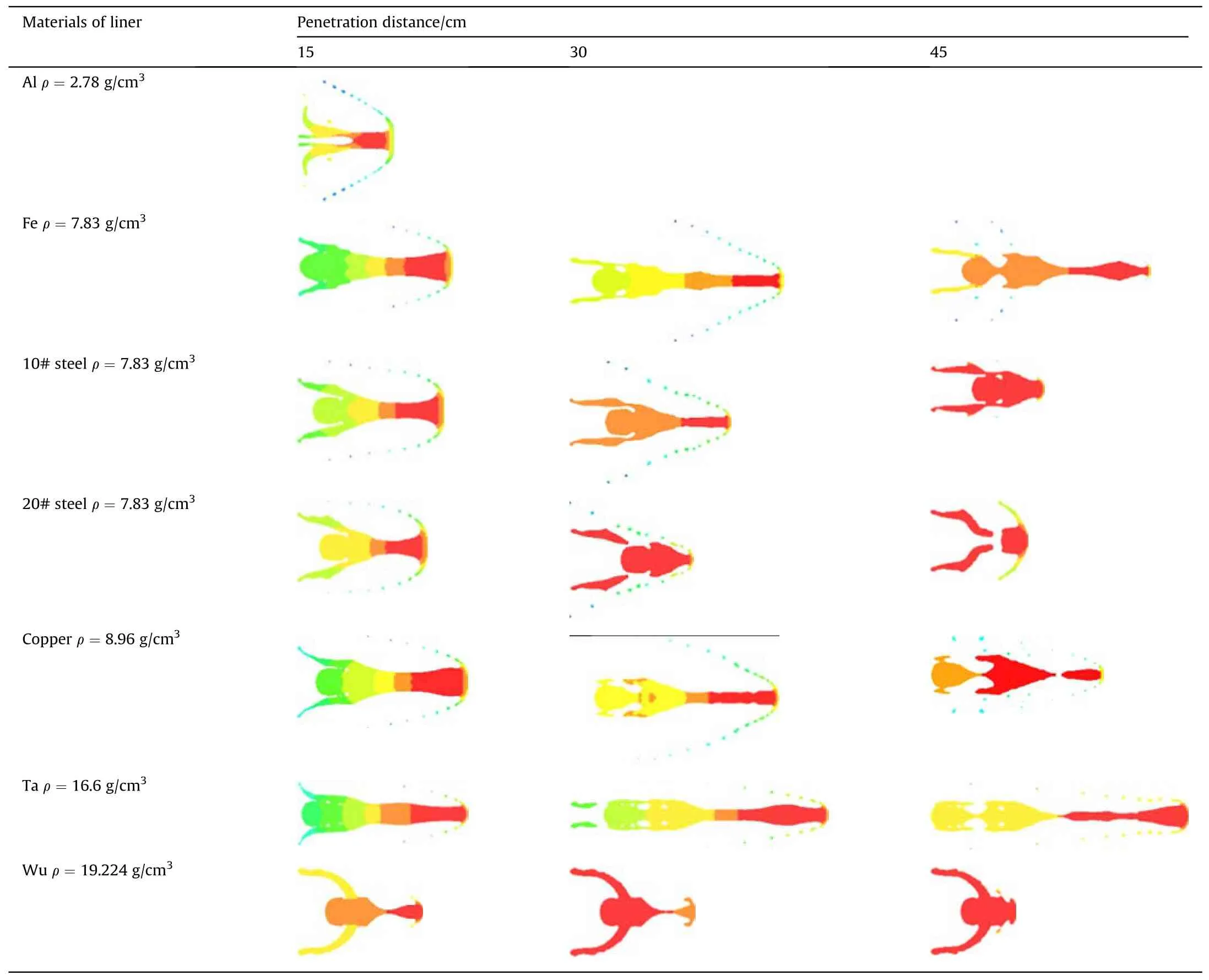
Table 7 Morphological changes of JPC in water under different liner’s materials.
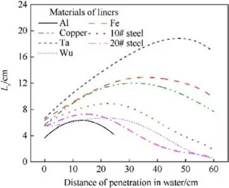
Fig.18.Variation in length of JPC with material of liner.
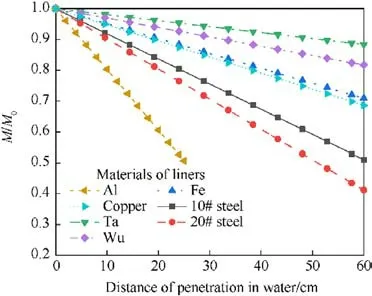
Fig.19.Relative mass with material of liner.
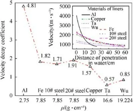
Fig.20.Variation in velocity of JPC with material of liner.
In conclusion, the research has shown that the density of the liner is a key factor in the movement characteristics of the JPC in water, with high density JPC has better underwater penetration capability.Copper, Fe and tantalum liners can form JPC and are suitable for the penetration of multi-layer protective structures.On the other hand,tungsten liners can form EFP with a large diameter,and are suitable for penetrating single layer protective structures,causing large diameter perforation damage.
3.3.Influences of the aspect ratio of the charge
The diameter of the charge was kept constant while the aspect ratio of the charge was increased by changing the height of the charge in increments of 0.25 from 0.5 to 1.5.Table 8 shows the effect of aspect ratio of the charge on the JPC forming effect.The numerical calculations revealed that increasing the charge mass while maintaining the same concentration of the liner can result in the JPC acquiring higher kinetic energy and velocity gradients.This leads to a greater degree of stretching of the JPC and a larger effective length, as illustrated in Fig.21.Further analysis indicated that when the aspect ratio of the charge is greater than 1.25,there is no significant difference in the morphology of the JPC, and the effective length gradually increases with the increase in the charge aspect ratio, but the rate of increase decreases gradually.Fig.22 shows the mass loss rate with the aspect ratio of the charge.It is found that there is no strict relationship between the aspect ratio of the charge and the mass loss rate,but the effect of the aspect ratio of the charge is smaller.
The charge aspect ratio has a significant impact on the growth process of the detonation wave, which will affect the pressure acting on the wall of the liner,thus affecting the jet molding effect.Fig.23 shows the detonation pressure clouds with different charge aspect ratios when the detonation wavefront surface reaches the top of the liner.The results indicate that a spherical blast wave is formed after the detonation of a point in the center of the charge tail.With an increase in the charge aspect ratio, the blast wave growth time is more adequate, resulting in a larger radius of the blast wave when it reaches the top of the liner, which leads to a smaller angle between the blast wave front and the outer wall of the liner.A smaller angle increases the pressure acting on the liner and increases the crushing velocity of the liner, which is more conducive to the tensile forming of the JPC.However,as the charge aspect ratio increases further, the difference in the blast wave gradually decreases.Therefore, when the charge aspect ratio is greater than 1.25,the influence of the charge structure parameters on the JPC forming is less significant.
Fig.24 illustrates the relationship between the velocity decay coefficient of the JPC and the aspect ratio of the charge.As depicted in the figure, the velocity decay coefficient demonstrates an exponential increase with the charge aspect ratio.However, once the charge aspect ratio surpasses 1.25, further increases in the aspect ratio exert a diminishing effect on the velocity decay coefficient.The primary reason for this observation is that the effective charge mass increases exponentially with the charge aspect ratio.Yet, the mass of the effective charge approaches a limiting value after the charge aspect ratio has reached a certain threshold.Consequently, the velocity decay coefficient of the JPC exhibits minimal variation when the charge aspect ratio is greater than 1.25.
From these findings, it can be concluded that when the aspect ratio of the charge is greater than 1.25,the influence of the charge structure on the characteristics of the JPC in water is not significant.
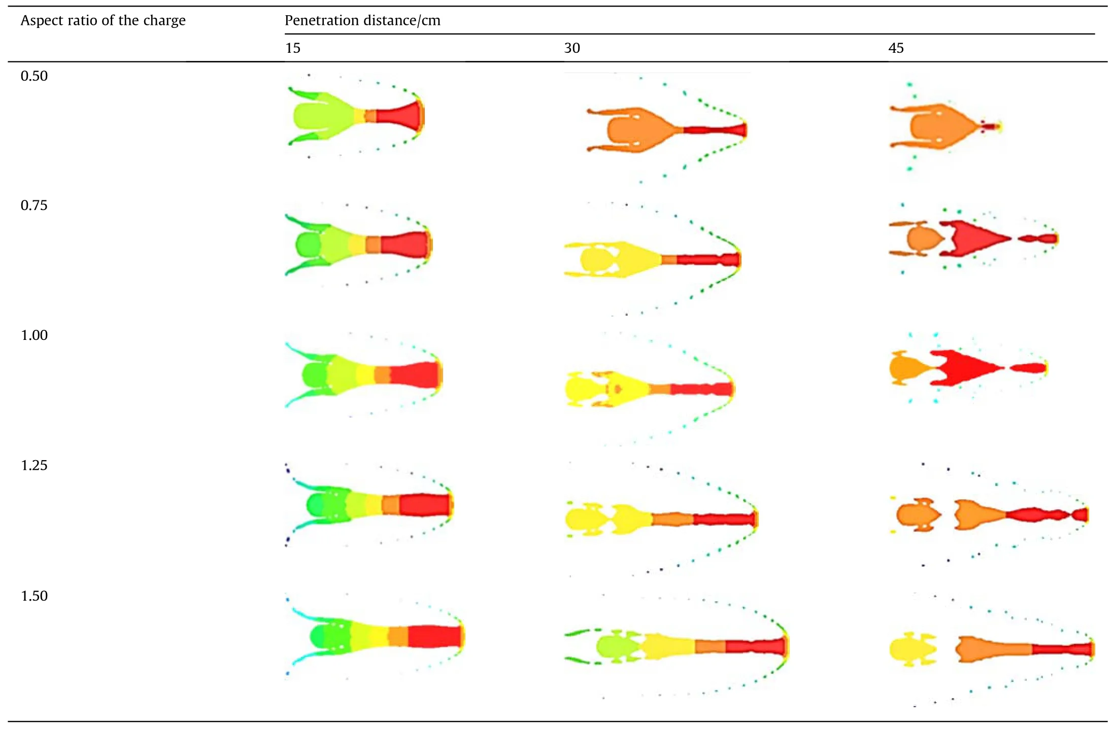
Table 8 Morphological changes of JPC in water under different aspect ratio of the charge.
3.4.Influences of the stand-off distance
The other parameters of the warhead held constant, the standoff distance is increased in increments of 0.25 Dk,ranging from 0.25 Dkto 2.0 Dk.Fig.25 displays the variations in the penetrator shape upon water entry for different stand-off distances.As demonstrated in Fig.25, the stand-off distance significantly impacts the penetrator shape at the moment of water entry.As stand-off distance increases, the shape of the penetrator upon water entry progressively transitions from EFP to JPC.As depicted in Fig.26,the stretch of JPC is positively correlated with the increase in stand-off distance, which in turn, results in an enhanced effective length of the JPC in water.Consequently, a larger stand-off distance contributes to a longer effective JPC length within the water.Shows the mass loss rate at different bomb heights.As shown in Fig.27, the mass loss rate at bomb heights of 0.25Dkto 1Dkis lower than that at bomb heights of 1.25Dkto 2.0Dk,The main reasons for this are the low velocity and the short structure of the jet at a stand-off which ranges from 0.25 to 1 Dk, these two factors both contribute to a reduction in the mass loss rate of the jet.
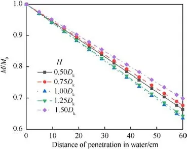
Fig.22.Relative mass with aspect ratio of the charge.
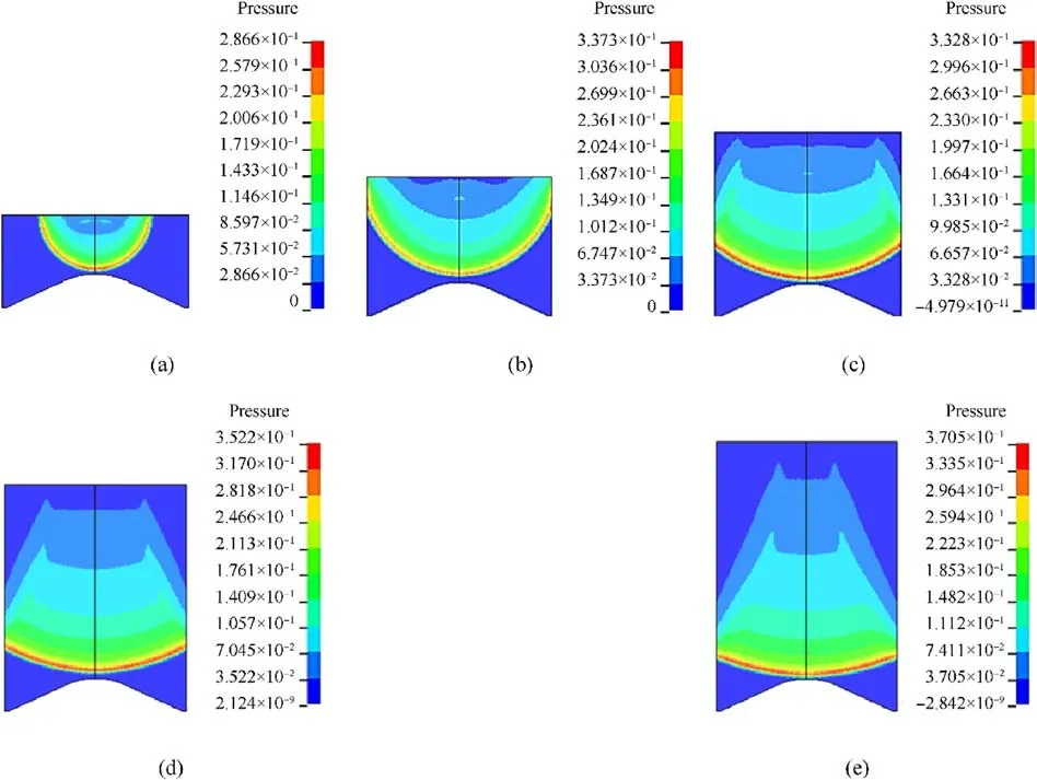
Fig.23.Detonation pressure cloud for the charge: (a) H/Dk = 0.5; (b) H/Dk = 0.75; (c) H/Dk = 1.0; (d) H/Dk = 1.25; (e) H/Dk = 1.5.
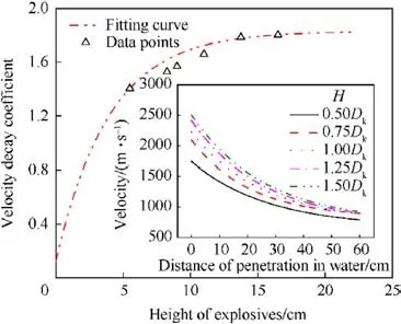
Fig.24.Variation in velocity of JPC with H.
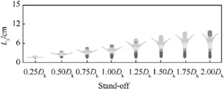
Fig.25.Morphology of penetrators at the moment of entry into the water with standoff distance.
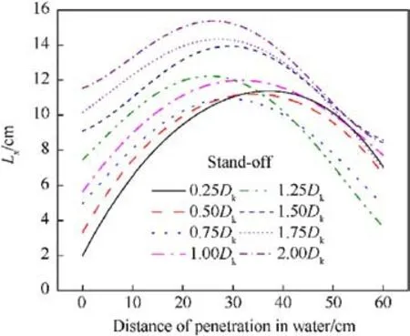
Fig.26.Variation of the effective length with stand-off distance.
Fig.28 displays the velocity decay coefficients for different stand-off distance values.The results show that when the stand-off distance is between 0.25Dkand 1.25Dk, the velocity decay coefficient oscillates between 1.57 and 1.63 with an amplitude of 3.7%.This indicates that the changes in the velocity decay coefficient are small for stand-off distance values lower than 1.25Dk.However,when the stand-off distance is greater than 1.25Dk, the velocity decay coefficient gradually decreases in an approximately linear fashion with the increase of stand-off distance.This phenomenon can be attributed to the degree of stretching of the penetrator.When the stand-off distance is lower than 1.0Dk, the penetrator is less stretched and has a larger contact area with the water.This results in a higher resistance to the penetrator and a higher velocity decay coefficient.As the stand-off distance increases further, the degree of stretching of the penetrator increases, reducing the contact area between the penetrator and the water.Consequently,the resistance to flight in the water decreases, resulting in a decrease in the velocity decay coefficient as the stand-off distance increases.
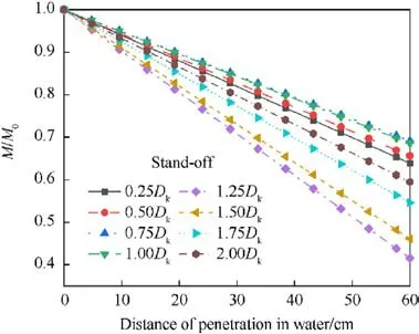
Fig.27.Relative mass with stand-off distance.
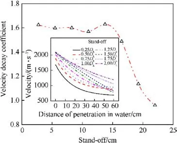
Fig.28.Variation of velocity and decay coefficients with stand-off distance.
The research findings suggest that increasing the stand-off distance can improve the effective length and velocity storage capacity of the penetrator in the water.However, if the stand-off distance is too high, the penetrator may become excessively stretched,leading to poor continuity of the cavity in the water and failure to achieve the cavity-following effects.Based on the results,it can be concluded that the stand-off distance of the warhead should be within 1Dkto enhance the underwater action effect of the JPC.Within this range,the degree of stretching of the penetrator is optimal, allowing for efficient penetration and cavity-following effects.
4.Conclusions
The mechanism of JPC penetration and movement characteristics in water were investigated by employing a combination of numerical simulations and experimental approaches.Several conclusions are presented as follows:
(1) There are two effects when JPC penetrates in water:velocity decay and mass erosion.During this process, the effective length initially increases and subsequently decreases, the mass of the JPC decreases approximately linearly, while the velocity undergoes an exponential decay in water.Based on theoretical analysis,a specific formulation for velocity decay has been derived: vx= v0×e-Kx;
(2) Without changing the configuration of the liner, increasing the thickness and the stand-off distance can improve the erosion resistance and velocity storage capacity of JPC, the optimal values of the liner thickness is 0.0363Dk-0.0545Dk,the stand-off distance should be within 1.0Dk。Increasing the aspect ratio of the charge can increase the stretching of the JPC and obtain an effective length of larger penetrators, but with a charge aspect ratio higher than 1.25, the influence of the charge structure on the movement characteristics of the JPC in water is not significant;
(3) The velocity decay law of JPC during water penetration is significantly influenced by the density of the material.Higher density materials tend to exhibit slower velocity decay.When densities are similar,the velocity decay law tends to be uniform.Based on the erosion resistance of JPC,research has shown that liners made of copper, Fe and tantalum can be used to form JPC that are suitable for penetrating multi-layer protective structures.On the other hand, tungsten liner can form an EFP with a large diameter and has a high velocity storage capacity in water.It is suitable for penetrating single layer protection structures,but it can cause damage to large diameter perforations.
Declaration of competing interest
The authors declare that they have no known competing financial interests or personal relationships that could have appeared to influence the work reported in this paper.
Acknowledgments
This work was supported by the National Natural Science Foundation of China (Grant No.11672278).
- Defence Technology的其它文章
- Evolution of molecular structure of TATB under shock loading from transient Raman spectroscopic technique
- MTTSNet:Military time-sensitive targets stealth network via real-time mask generation
- Vulnerability assessment of UAV engine to laser based on improved shotline method
- Free-walking: Pedestrian inertial navigation based on dual footmounted IMU
- Investigation of hydroxyl-terminated polybutadiene propellant breaking characteristics and mechanism impacted by submerged cavitation water jet
- Estimation of surface geometry on combustion characteristics of AP/HTPB propellant under rapid depressurization

