Investigation of hydroxyl-terminated polybutadiene propellant breaking characteristics and mechanism impacted by submerged cavitation water jet
Wenjun Zhou, Meng Zhao, Bo Liu, Youzhi Ma, Youzhi Zhang, Xuanjun Wang
Zhijian Laboratory, Rocket Force University of Engineering, Xi’an, 710025, China
Keywords:Submerged cavitation water jet Hydroxyl-terminated polybutadiene propellant Breaking characteristics Failure modes
ABSTRACT A submerged cavitation water jet(SCWJ)is an effective method to recycle solid propellant from obsolete solid engines by the breaking method.Solid propellant’s breaking modes and mechanical process under SCWJ impact are unclear.This study aims to understand those impact breaking mechanisms.The hydroxyl-terminated polybutadiene (HTPB) propellant was chosen as the research material, and a selfdesigned test system was used to conduct impact tests at four different working pressures.The highspeed camera characterized crack propagation, and the DIC method calculated strain change during the impact process.Besides, micro and macro fracture morphologies were characterized by scanning electron microscope (SEM) and computed tomography (CT) scanning.The results reveal that the compressive strain concentration region locates right below the nozzle, and the shear strain region distributes symmetrically with the jet axis,which increases to 4%at first 16th ms,the compressive strain rises to 2%and 6%in the axial and transverse direction,respectively.The two tensile cracks formed first at the compression strain concentrate region, and there generate many shear cracks around the tensile cracks, and those shear cracks that develop and aggregate cause the cracks to become wider and cut through the tensile cracks, forming the tensile-shear cracks and the impact parts eventually fail.The HTPB propellant forms a breaking hole shaped conical after impact 10 s.The mass loss increases by 17 times at maximum, with the working pressure increasing by three times.Meanwhile, the damage value of the breaking hole remaining on the surface increases by 7.8 times while 2.9 times in the depth of the breaking hole.The breaking efficiency is closely affected by working pressures.The failure modes of HTPB impacted by SCWJ are classified as tensile crack-dominated and tensile-shear crack-dominated damage mechanisms.
1.Introduction
Solid propellants are high-energy materials used as rocket fuels in rocket engines [1-4].Upgraded engines have rendered older engines obsolete,and it is necessary to address them promptly.The separation-recycle method is a recommended solution, offering economic and environmental benefits over conventional methods[5-11].This method aims to separate the solid propellants from the shell in a fractal manner and recycle the high-energy materials and the engine shells separately.As energetic materials pose a high risk,it is a crucial step that ensures the safe and efficient removal of solid propellants.Its low working pressure, efficiency, and noncontaminating properties make cavitation water jet (CWJ) a highly sought technology, cavitation is a commonly observed phenomenon in fluid mechanics.The collapse of cavitation bubbles generates micro-jets and shock waves, with the peak amplitude pressure of cavitation collapse between 102-104MPa generally accepted by researchers [12-17].CWJ contains huge cavitation bubbles that develop into period clouds and shoot downstream.When there is a local of the materials, the collapse of those cavitation clouds generates a huge powerful mechanical force.CWJ is usually compared with a high-pressure water jet.Previously published reports[18,19]stated that the impact pressure of CWJ is 8.6-124.0 times that of a continuous jet,so the breaking efficiency of CWJ can work at lower working pressure conditions, which is similar to that of a high-pressure water jet under conditions of high working pressure.One of the primary reasons for a safe cutting method for energetic materials is relatively low working pressure(about 10-30 MPa) rather than high-pressure water jets.To improve the cavitation effect as well as ensure safety and maximize efficiency, the submerged cavitation water jet (SCWJ) was employed, and the nozzle and the sample were submerged in water.Despite its potential for dealing with high-energy materials,SCWJ technology in the breakage and slicing of solid propellants has not been extensively researched.
Solid propellants under SCWJ impact break, damage, and fail uncertainly.This makes investigations into these properties crucial for understanding the breaking process and guiding engineering applications.Solid propellants are heterogeneous mixtures of materials.An impact force causes the material to change mechanically.Failure modes may be reflected in the whole mechanical change process.As the CWJ is a high strain rate impact force, its failure modes differ from low strain rate impact, which is often studied and explored.In previous limited studies, Zhang [20-22]researched the application of SCWJ to cut explosives and powders,and numerical simulation research was conducted on the mechanical response of the cutting process.In addition to the above literature,there is no other literature that illustrates fragmentation characteristics and processes.The SCWJ is always applicated to cutting and crushing coal and rock [23,24].Generally, the morphology after fracture and the mechanical change mode in the impact process may judge the failure modes.Authors referred to these methods to study cavitation water jet breaking solid propellants.
To non-destructively observe the final shapes of breaking morphology, computed tomography (CT) was adopted.Wang [25]used micro-CT to scan the damage morphology of the tensioncompression zone to analyze the failure mode under biaxial tension and compression loading test of Hydroxyl-Terminated Polybutadiene propellant (HTPB) and Nitrate-Ester Plasticized Polyether(NEPE)solid propellants.While CT results can reveal the final stage of fracture characteristics and damage evolution, it doesn’t capture the dynamic process of breaking under the complex flow environment.In solid mechanics, the digital image correlation (DIC) method is often used to quantify full-field deformation.Chen [26]executed the standard relaxation tests and uniaxial tension of the HTPB propellants test under different velocities, where the DIC technique was applied to record deformation.Lv [27]studied the stress relaxation and uniaxial constant tensile rate tests, which were carried out to measure the viscoelastic Poisson’s ratio of the composite solid propellants according to the stress characteristics of solidification cooling and ignition pressurization conditions through the DIC system.Based on the above, the DIC method captures changes in the displacement and strain fields.This approach provides a more comprehensive understanding of the deformation and breaking behavior of solid propellants under cavitation clouds.
The strain variation of solid propellants during the impact process determines the crack development trend and ultimate breaking morphology, which can explain the failure mode during the impact process.To evaluate the fracturing behavior and failure mechanism,HTPB propellants were selected as the research object,and impact tests were conducted under four working pressures on a self-developed experimental platform.CT scanning was used to visualize breaking characteristics and damage evolution in the four breaking HTPB propellants.The DIC method was utilized to capture the surface deformation of HTPB propellant specimens, and the local displacement and strain fields were applied to understand the breaking process and failure mechanism.SEM observed microscopic features of breaking HTPB propellants.Finally, the failure modes of HTPB propellants were investigated using SCWJ based on the experiment.Previous research on the damage characteristics and failure modes of solid propellants under SCWJ impact is limited, and this study aims to fill this knowledge gap.
2.Experiments
2.1.Experimental materials
The experimental material used in this study is a typical triplecomponent HTPB propellants based composite solid propellants.These propellants comprise a hydroxyl-terminated polybutadiene rubber matrix containing ammonium perchlorate (AP) particles and aluminum particles (Al).The tensile strength is 4 MPa,compressive strength is 10 MPa,and shear strength is 108 MPa.
2.2.Experimental system
The impact experimentation was conducted using an SCWJ technology system developed by the authors, which comprises a water storage tank, a high-pressure water pump, a test tank, a control platform,and a wastewater tank,as illustrated in Fig.1.The maximum pressure of the water pump is 35 MPa,the test tank is a cuboid polymethyl methacrylate transparent tank.Tap water was used as the jet medium, and the test temperature was room temperature.The jet pressure is challenging to measure during impact.Therefore,in this study,the jet pressure is represented by the pump pressure, which is easy to control and measure, denoted as the working pressure.The working pressures are changed by adjusting the pressure compressor.The standoff distance is adjusted by elevating or lowering the lifting rod on a control platform.When the test water reservoir is replenished after each impact test, the test water tank has a drainage hole on one side,which maintains a constant water level during the experiment process,and maintains continuous surrounding pressure.The HTPB propellants sample blocks were affixed to the central platform at the bottom of the test tank, directly beneath the corner nozzle, with a diameter value of 1.3 mm.Turning on the pressure pump caused a cavitation water discharge to form in the nozzle, which was then injected into the test water tank and ultimately impacted the samples.The impact experiments set the working pressures as 7.5, 12.5, 17.5 and 22.5 MPa,and the standoff distance was 45 mm.The experimental time was 10 s.In addition, in the DIC research experiment, to observe the changing process of solid propellants and eliminate the influence of water flow disturbance on the shooting results of highspeed camera, the width of the experimental water tank was reduced by half based on the original experimental setup.The side of the solid propellants was close to the side wall of the water tank when experimenting.A high-speed camera was placed directly before the solid propellants to collect pictures of the impact process.
The ultra-high-speed photography system was used, which included signal sources, fill light systems and ultra-high-speed camera.The system also included three software sections for analysis and a specimen loading system.The DIC method works when the relative value of the grayscale remains constant,allowing for matching identical pixels in two pictures before and after deformation to track pixel motions.Image correlation and numerical processing can then be utilized to obtain the strain and displacement fields.It’s crucial to create an artificial speckle field on the surfaces of the specimens being examined,which is achieved by spraying a thin,homogeneous background coat of white paint onto the surfaces of the specimens.Once the basecoat was dry,an expert sprayed it with black paint in a random pattern to create speckles.White paint was applied to all the samples to track cracks progression over time, and the specifications for the speckle pattern are detailed in Refs.[28,29].
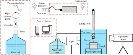
Fig.1.Schematic diagram of SCWJ breaking HTPB propellants experiment system.
2.3.Experimental procedures
After impacting the sample, the damaged sample was dried at 40°C, and the breaking samples were measured by CT scanning instrument typed Y.CT Precision.The sample was placed on the platform and scanned with X-rays, yielding slice images.Breaking depth,equivalent diameter,and mass loss of the breaking hole were chosen as assessment indices to objectively evaluate the breaking ability of SCWJ on the HTPB propellants.The depth (D) represents the total height of the breaking hole,and the XY,XZ,and XZ planes were denoted by the coordinate axes, as shown in Fig.2(a).The equivalent radius(R)of a circle of the same size as the breaking hole was used to characterize the breaking area on the surface,as shown in Fig.2(b).The breaking sample was also submitted to SEM testing type VEGA II XMU of Shimadzu, the wall surface of the breaking hole was scanned, and the sections around the breaking hole wall were also scanned.
Based on the sequential speckle images taken during the tests,VIC2D software was used to post-process the captured images.The basic principle of DIC calculation can be referred to Refs.[30,31].Procedures are shown in Fig.3.The steps involve: importing the continuously recorded speckle pictures into VIC2D software;choosing a distorted image and the image before deformation as the target and reference,respectively;selecting a region of interest(ROI) in the speckle images and creating the surface component and simulating the deformation.Split this area into many smaller subsets of equal size, and note the references of their respective centroids; the final step is to use a digital image processing technique to calculate the displacement and strain by looking for the matching subsets in the target picture and pinpointing their centroids’positions.A NAC ACS-1 M40E high-speed camera and an LED lamp (Danny U, 200 W) were located on the sample at 60 cm distances to get clear images for DIC post-processing.A 311 × 300-pixel matrix for the zone of interest (ROI) (~13.8 pixels/mm) in Fig.3(a), and 120000 frames/s (~8.3 μs interval) were used to experiment with an exposure time of 3.4 μs,and the data collection time is 1.4 s.Before the experiment began,the shot was corrected,as shown in Fig.4(a).The reference image was used for DIC calculation analysis, as shown in Fig.4(b).
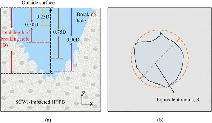
Fig.2.Several relative heights of (a) impacted-HTPB propellants; (b) The equivalent radius definition.

Fig.3.Flow chart of deformed calculation by DIC experiment analysis.
3.Results and discussion
3.1.Macro and micro characteristics of SCWJ-impacted HTPB propellants
3.1.1.Damage development process
Prior to cracks development, HTPB propellants undergo cumulative internal damage under SCWJ.This leads to crack development and growth trends.Nephograms of the displacement and strain field were created through DIC experiments at 22.5 MPa, as shown in Fig.5.
At first, the displacement and strain fields did not exhibit an obvious pattern.HTPB propellants are heterogeneous viscoelastic materials with many defects; the materials may situate at the compaction stage at impact first, as shown in Figs.5(a-1)-5(e-1).As the impact time increases, the regions directly beneath the cavitation cloud experience the most significant change in axial displacement.The strain concentration occurs roughly 10 mm from the surface directly beneath the SCWJ in a negative direction, as indicated by the blue shaded area in Figs.5(a-2) and 5(b-2).The local axial strain values have been observed to increase along the symmetrical distribution of the SCWJ axis.As a result of the reflection, propagation, and diffusion of stress waves within the internal structure, the region surrounding the jet axis shifts in the opposite direction, while the surface edge is subjected to the stretch effect caused by backflow, as can be observed in the red regions in Fig.5(b-2).Simultaneously,the transverse displacement distributes symmetrically along the SCWJ’s axis with equal magnitudes and opposite orientations, and the transverse strain fields continue to exhibit strain concentration phenomena directly beneath the SCWJ.As the impact accumulates, the displacement and strain are similarly distributed along the jet axis,increasing the value.As shown in Figs.5(e-2)-5(e-5),the particles around the axis are subject to shear strain throughout the impact process.The shear strains are symmetrical about the jet axis and in the opposite direction.In the DIC analysis process,cracks always result in speckle discontinuity; as shown in Figs.5(a-4)-5(d-4), the cracks have already formed.As the damaging impact accumulates,the axial and transverse strain fields concentrate, exceeding the plastic strain of HTPB propellants, and cracks appear directly below the jet at the strain concentration region at the impacted time t = 132.8 ms.A large breakage area occurs in the strain concentration area,and this area fails.Under SCWJ, the maximal values of the axial displacement and strain field nephograms move downward, the strain concentration area moves down, and a new fracture surface appears finally.

Fig.4.(a) Calibration image; (b) Reference image of DIC analysis.
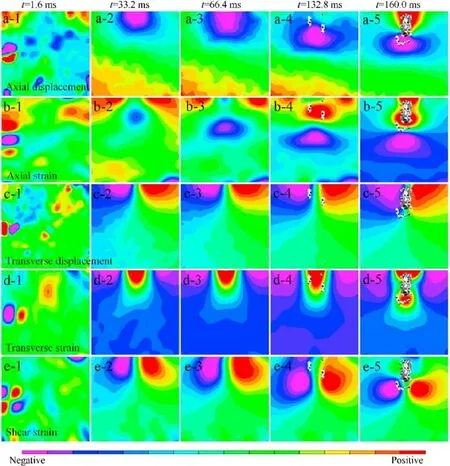
Fig.5.(a) Local axial displacement;(b)Local axial strain;(c)Local transverse displacement;(d)Local transverse strain;(e)Local shear strain field of ROI in HTPB propellants.The corresponding time of each column from left to right (a-1-a-5, b-1-b-5, c-1-c-5, d-1-d-5, e-1-e-5) is 1.6 ms, 33.2 ms, 66.4 ms,132.8 ms, and 160.0 ms, respectively.
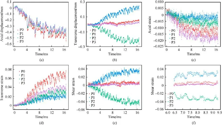
Fig.6.Time dependence of local axial and transverse strain and displacement of HTPB propellants: (a) Axial displacement; (b) Transverse displacement; (c) Axial strain; (d)Transverse strain; (e) Shear strain; (f) The shear train of three periods of cavitation cloud.
The mass points P0, P1, P2, and P3 were selected for analysis during 16.6 ms (first 2000 frames) to analyze the local displacement and strain fields quantitatively.Mass point P0 is located directly beneath the SCWJ at 4 mm from the edge of the HTPB propellants surface.Mass points P1 and P2 are located 4 mm to the left and right of P0, respectively.Mass point P3 is located directly beneath P0 at 4 mm.The accurate locations of these four mass points are shown in Fig.4(b).The transverse and axial strain change of those four mass points is plotted in Fig.6.The axial displacements increase progressively, and the direction is negative, indicating mass points compression.The P1 and P2 increase to 0.47 mm in displacement,whereas the P0 is 0.56 mm,while the P3 decreases by 18%compared to the P0 due to the stress wave weakening as it reaches P3.The axial strain increased in the opposite direction,and the change in P0 and P3 is greater than the change in displacement compression of P1 and P2 mass points,causing the compression of the mass points directly beneath the jet to be greater than the compression of the mass points in the surrounding region.P1 and P2 transverse displacement increases and decreases to plus and minus 0.28 mm, respectively.The displacement changes between P0 and P3 are greater than between P1 and P2.The field increases,and the increase of P0,P3 is greater than that of P1,P2 in axial and transverse strain.As for shear strain, the shear strains P1 and P2 are+0.03 and -0.03, respectively,and the values of P0 and P3 are approximately 0.01.In the first 4 ms of the jet impact, the displacement and strain trend of P0-P3 is not evident and is in the compaction stage.Nerveless, after the cumulative jet impact, the difference between the masses becomes evident, particularly between the P0 and P3 masses directly below the jet and the surrounding masses, and changes in the trends of P1 and P2 are distinct, which may lead to the break and further failure in the strain change region.The SCWJ periodically generates cavitation clouds in the submerged flow field,which then impact the surface of HTPB propellants, as shown in Fig.6(f).The period of the variations is 1.04 ms, which is almost identical to cavitation clouds.Cavitation clouds period is 1.10 ms in our previous studies.Damage accumulation leads to an increase in displacement and strain.Consequently,the displacement change increases continuously and periodically, leading to cumulative damage breaking.Under SCWJ,the compression strain concentration area is located right below the nozzle,and the shear strain region is distributed symmetrically.Shear strain change reached 4% at first 16 ms while compressive strain reached 2% and 6% in the axial and transverse direction,respectively.
3.1.2.Cracks development process
As the strain accumulation exceeds the plastic strain, HTPB propellants form cracks.The characteristics of the cracking process were studied at six different time points,as shown in Fig.7.At the beginning of cracks formation, two primary cracks T1 and T2 marked in red are obviously, parallel to the impact direction, as shown in Fig.7(a).With increasing impact time,the cracks T1 and T2 expand along the radial direction as shown in Figs.7(b)and(c),and many micro cracks are formed around the primary cracks T1 and T2.Microcracks develop and cluster with other microcracks and then cut through the primary crack T1,and T1 is widened and finally changes the direction as shown in Fig.7(d),which develops and cracks into more cracks,as shown in Fig.7(d)marked the in the yellow part,and those new cracks developed cut through with the T2 primary crack, causing the T1 and T2 cracks to link together,as shown in Fig.7(e), cause matrix breakage finally as shown in Fig.7(f).
The fractal dimension is utilized to quantify the complexity and irregularity of cracks, with the box dimension method being the most utilized [32].The fractal dimension is numerically calculated in this study using the box dimension method.The fractal dimensions and the cracks area percent of each time point are calculated as shown in Fig.8.Constantly forming and expanding,the micro-cracks increase in area as time passes, but the rate of increase varies between periods.In less than 165.9 ms,the cracking area changes, and the rate is 0.019; after 165.9 ms, the rate increases by approximately five times.The fractal dimensions increase linearly from 1.038 to 1.391 before decreasing to 1.325,consistent with the reduction of microcracks cut-through to the main crack and fracture disorder.When a wide fracture forms,pressure swelling and water reflux with a certain velocity can cause the formation of new microcracks at the primary crack edge,thereby increasing the fractal dimension to 1.491.The cracks area increases with time increasing,17 times with time within 200 ms.
3.1.3.Breaking characteristics of the SCWJ-impacted HTPB propellants
3.1.3.1.Surface characteristics of the SCWJ-impacted HTPB propellants.To accurately understand the final stage of breaking characteristics, the four SCWJ-impacted HTPB propellants samples impacted by the working pressure of 7.5,12.5,17.5, and 22.5 MPa were chosen for analysis, and these four samples are denoted as samples A,B,C,and D,respectively.A high-precision digital camera was used to capture visible fractures on the external surfaces of HTPB propellants samples.SEM and CT tests were used to observe the damage phenomenon of the breaking holes.
The surface characteristics of the breaking HTPB propellants are shown in Fig.9.The damaged area on the surface of sample A is close to a circle,and no crack is visible.The damaged area of sample B expands,and the shape no longer resembles a circle but becomes irregular.The damaged area of sample C is larger than that of sample B, and the damaged shape is not circular.Sample D has a damaged area nearly oval,with three visible cracks on the surface.The surface damage area increases as the working pressure increases,and the surface shape is different.
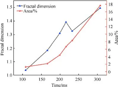
Fig.8.Variation trend and the law of fractal dimension and cracks area percent of cracks at different times.

Fig.7.Cracks images of HTPB propellants impacted by SCWJ.The(a)-(f)pictures represent the impact time(a)107.4 ms;(b)165.8 ms;(c)199.2 ms;(d)215.9 ms;(e)232.5 ms;(f)307.5 ms, respectively.

Fig.9.Surface characteristics of the SCWJ-impacted HTPB propellants: (a) A; (b) B; (c) C; (d) D.
3.1.3.2.Slice images of SCWJ-impacted HTPB propellants.
Information on the inside of damaged holes is critical to understanding the damage process.The SCWJ-impacted HTPB propellant was subjected to CT scanning tests; slice images were obtained at various depths in the SCWJ-impacted HTPB propellant breaking holes.The four breaking planes in the Z-axis direction of the breaking holes were chosen for analysis of the breaking characteristics as shown in Fig.10, that is, 0.25-times, 0.5-times, 0.75-times, and 0.9-times total depth of the breaking hole, denoted as 0.25D, 0.5D, 0.75D, and 0.9D for each SCWJ-impacted HTPB propellants.The D is the total depth of the breaking hole,as shown in Fig.2.The binarization method was used to segment the slice images, the white areas represent solid surfaces, and the black areas represent holes and cracks.Fig.11 shows binarized images of various areas of the samples at various depths.At the same time,the equivalent radius (R) values are plotted in Fig.12.
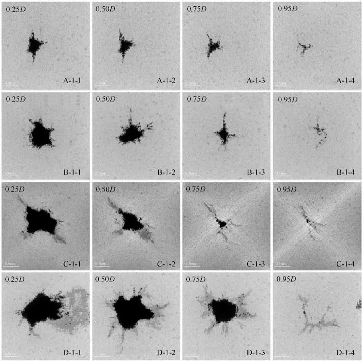
Fig.10.CT slice images obtained in the XY plane at different depths.A: impacted at 7.5 MPa; B: impacted at 12.5 MPa; C: impacted at 17.5 MPa; D: impacted at 22.5 MPa.
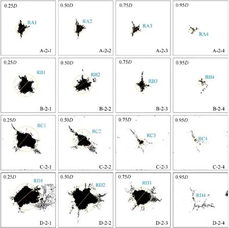
Fig.11.Binarized images of CT slice images in the XY plane at different depths and the equivalent diameter diagrams of each slice.A:impacted at 7.5 MPa;B:impacted at 12.5 MPa;C: impacted at 17.5 MPa; D: impacted at 22.5 MPa.
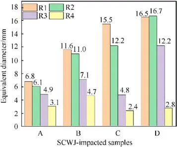
Fig.12.R value of CT slice images at different depths in the XY plane.A: impacted at 7.5 MPa; B: impacted at 12.5 MPa;C: impacted at 17.5 MPa; D: impacted at 22.5 MPa.
As shown in Fig.10,the breaking distribution varies with depth.Sample A has limited damage distribution.The equivalent diameter of RA1 is 6.8 mm.At the 0.25D breaking plane, three fissures that form from the hole’s edge extend into the matrix.The R value is then reduced from 6.1 mm to 4.9 mm, and the breaking plane decreases 54.4% with the depth increasing from 0.25D to 0.95D,yielding four fissures.The breaking distribution is a minimum at the bottom of the hole.While the hole has not yet formed, only fissures are visible.In the case of sample B,the equivalent diameter RB1 value is 11.6 mm and no visible fissure is formed,when the hole depth increase to 0.5D,the RB2 value changes to 11.0 mm and there is a tendency for forming fissures, the RB3 value is reduced to 7.1 mm,resulting in the formation of two long fissures.From 0.25D to 0.95D breaking plane,the equivalent diameter R value decreased 59.4%.The equivalent diameter RC1 value is 15.5 mm at the 0.25D breaking plane,the fissure widens and becomes severely damaged in two parts.The equivalent diameter RC2 of the damaged hole is 12.2 mm,and the breaking shape surrounding the hole is the same as at 0.25D.The fissure area decreases as the hole depth increases,while the equivalent diameter R value of the damaged area decreases dramatically, from 0.25D to 0.95D, and the equivalent diameter R value decreased by 84.5%.Furthermore, sample D results differ from the above three pressure conditions.The equivalent diameter R value is 16.5 mm at 0.25D and decreases to 2.8 mm at the bottom of the hole before increasing to 16.7 mm at 0.5D.From 0.25D to 0.95D,the equivalent diameter R value decreased by 83.0%.In all, the results of the 0.5D slice image show that the number of fissures is greater than that of samples A, B, and C at similar times of depth, fissures extending into the matrix around the hole edge grow in number but shrink in length.However, the fissures at the bottom of the hole are also longer than in the other conditions.The pressure is high, the damaged area is large, and more fissures are formed in the 0.9D breaking plane of A,B,C,and D.
The binarized slice images representing the hole centrally in the XZ and YZ planes are shown in Fig.13.The holes in samples A,B,C,and D are dissymmetric in the main damage area in the direction of the jet impact.The surface damage area is greatest for breaking samples A,B,and C.In sample D,the maximum damage area in the XY plane is approximately 0.25D.The damaged area decreases as the height increases.Many fissures extend from the hole edge into the matrix.
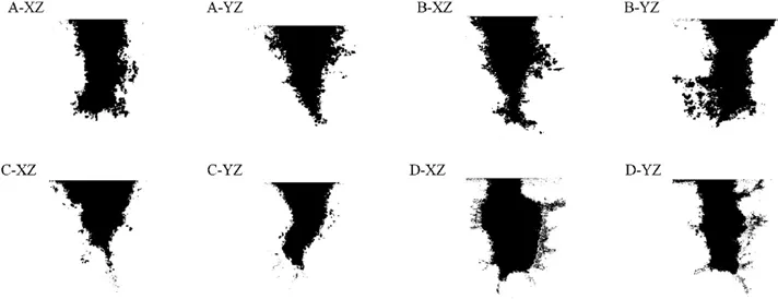
Fig.13.Binarized images of CT slice images obtained at the center of the hole in YZ and XZ planes.A: impacted at 7.5 MPa;B: impacted at 12.5 MPa;C: impacted at 17.5 MPa;D:impacted at 22.5 MPa.
3.1.3.3.Characteristics of breaking holes.Even though slice image analysis reveals HTPB propellants damage characteristics in some sections, the distance between different slices is relatively large,making it difficult to depict the sample’s three-dimensional (3D)damage distribution.Hence, this study used graphics processing software to turn the 2D slice data of the SCWJ impacted HTPB propellants into 3D models.Fig.14 depicts the 3D reconstruction results of the HTPB propellants breaking area impact by SCWJ.Quantitative analysis of HTPB propellants damage is needed to analyze the evolution of HTPB propellants damage in the axial direction.This paper used the damage value defined by area to represent the breaking degree of HTPB propellants[33].The sample is almost completely undamaged when the damage value is close to zero.While the damage value is close to one,the sample has been destroyed [34].The cross-sectional area of the HTPB propellants sample is defined as AT,ADis the total area of the holes and cracks in the cross-section,defined as the damage value,and Aefis the actual bearing area of the specimen.The ADplus Aefis equal to AT.HTPB propellant sample maintenance includes AP particles with a diameter of about 102μm.The AP particles have defective minute cracks due to the process of stress changes compared to the order of magnitudes of hole diameter equivalent value, those cracks defective can be ignored.The damage value resulting describes the jets’ breaking capability and reveals the HTPB propellant breaking mechanism impacted by the SCWJ.The damage values in the Z axial direction obtained from the 3D reconstruction are shown in Fig.15.
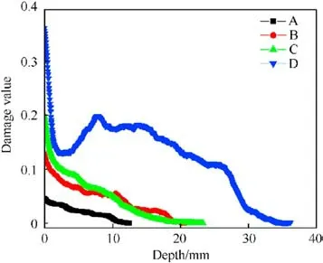
Fig.15.Damage value of every slice of the SCWJ impacted HTPB propellants in the Z axial direction.A: impacted at 7.5 MPa, B: impacted at 12.5 MPa, C: impacted at 17.5 MPa, D: impacted at 22.5 MPa.
The holes in samples A, B, C and D are conical.The red area represents the breaking holes, and the dark red edge area around the holes represents the damaged area in which the matrix was damaged did not fall off from the sample.This damaged area may include cracks and fissures.The breaking hole surface of the SCWJimpacted HTPB propellant, designated as the damaged surface, is riddled with tiny holes.The damaged wall’s roughness is related to the exposed AP easily dissolving in water and forming micro holes.According to the 3D reconstruction results,the damage of samples primarily forms a hole, with cracks and fissures surrounding the holes, which growth begins from the hole edge and extends into the matrix.Along the SCWJ impact direction, the damaged hole grows larger,more fissures form around the hole,and the damaged area increases around the hole, as seen from Figs.13 (D-XZ) and 13(D-XY).Furthermore, as the hole’s depth increases, the hole’s equivalent diameter decreases,and so does the damaged area.Only cracks form at the bottom of the holes.The damage value from the top to the bottom of the SCWJ-impacted HTPB propellant is shown in Fig.15.The damage value of sample A is approximately 0.05 at the damaged surface, 0.001 at the bottom, and the hole depth is 12.5 mm.Sample B is larger than sample A in damage value overall damage area.The surface damage value is about 0.13, which is 2.6 times that of sample A,the shape of the hole is analogous to that of sample A.The trend in the change of the damage value in sample B is analog to sample A.The large fissures around the hole cause the damage value difference in depth between 10.48 mm and 16.88 mm.In sample C, the hole depth is 23.28 mm, and the damaged area shrinks along the incidence direction.There are two visible cracks on either side of the hole, one of the cracks extends upward from the bottom of the hole.The depth of the hole in sample D is 36.04 mm, the shape differs from the other three samples and the depth of the hole increases, the damage area decreases first and then increases, reaching its maximum value at a height of 7.76 mm and damage area value 0.20.Based on the damaged value and the HTPB block sample volume,the mass loss of each sample was calculated and the value of them is 0.48,1.82,2.01,and 8.25 g.The working pressure increases by three times,and the mass loss of HTPB propellants under impacted by SCWJ is 17 times increase at maximum.The maximum damage value surface is always located in the sample impact surface,and the damage value is 0.046, 0.129, 0.200, and 0.362, respectively.The damage value increased by 7.8 times while 2.9 times in breaking hole in depth.

Fig.14.3D reconstruction results of SCWJ impacted HTPB propellants.(a) A: impacted at 7.5 MPa; (b) B: impacted at 12.5 MPa; (c) C: impacted at 17.5 MPa; (d) D: impacted at 22.5 MPa.
3.1.4.Micro characteristics of SCWJ-impacted HTPB propellants
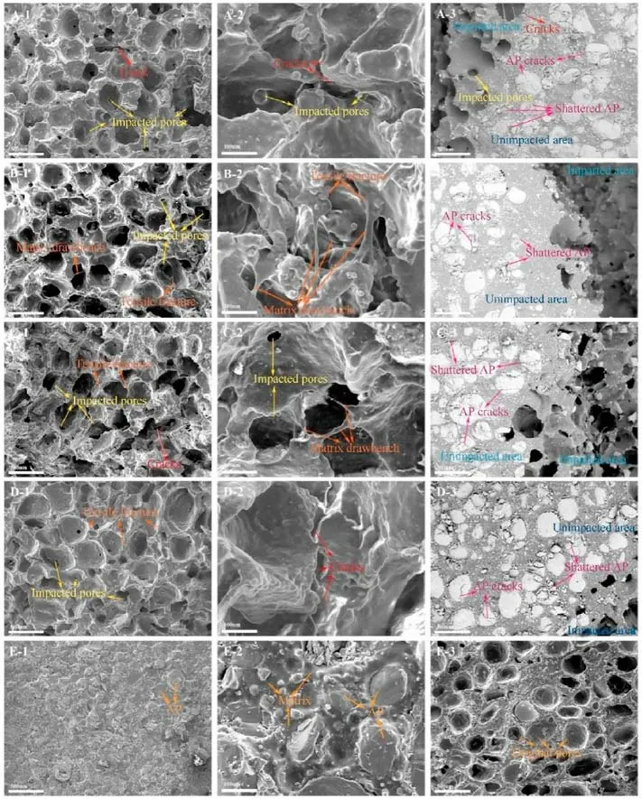
Fig.16.SEM images of the undamaged and SCWJ impacted HTPB propellants samples.A:impacted at 7.5 MPa;B: impacted at 12.5 MPa;C: impacted at 17.5 MPa;D: impacted at 22.5 MPa; E: undamaged HTPB propellants.
To learn more about how the HTPB propellants sample breaks,SEM was used to examine its micro characteristics and breaking morphology before and after the SCWJ impact test.The SCWJimpacted HTPB propellants, which include the damaged area and unimpacted area around the damaged hole wall,were scanned,the original HTPB propellants were also scanned, as shown in Fig.16.The experiment was conducted underwater, AP on the surface of HTPB propellants was dissolved before the impact, so the original matrix after dissolved AP was also analyzed by SEM as shown in Figs.16(E-1)-16(E-3).The original HTPB propellants consisted of an HTPB rubber matrix containing about 120 μm size AP particles and Al particles in 5-20 μm sizes.The AP particles and matrix can be seen with magnifications of 100 and 500 in Figs.16(E-1)and 16(E-2), respectively.A few AP particles have one crack due to small changes in stress during the manufacturing process.In the HTPB propellant sample damage area impacted by the SCWJ,there is only a matrix with many dense and unevenly sized pores as seen in Figs.16(A-1),16(B-1),16(C-1)and 16(D-1).There are two main ways to create those matrix micropores, on the one hand, the barely AP particles dissolve in water and remain the AP-holes when the matrix is torn,leading to the AP barely at the fissures on the other hand, those micropores are also formed by the shock wave and microjet produced by the collapsed cavitation bubbles.As for the Al powders, the Al powders are entirely coated in the matrix in the original HTPB propellants, as shown in Fig.11 (E-2).The SCWJ impacts the HTPB propellants, and the AP form more cracks before particles shatter and form intergranular cracks.As shown in Figs.16(A-3), 16(B-3), 16(C-3) and 16(D-3), the AP deformed by cracking and even shatters around the damaged area,resulting in a decrease in compressive strength of the HTPB propellants, the degree of shatter increased with increasing working pressure.When the damaged matrix falls off the sample, the Al powder is still coated in the matrix and separated from the sample along with the matrix,resulting in a small amount of Al powder dissolved in water.Furthermore, as shown in Fig.16(C-2), the matrix in the damaged area displays the “drawbench” indicating that the matrix is torn caused by tensile action.When a crack with a certain width is formed, the water with a velocity in the crack exerts pressure and swelling effect on the surrounding matrix.This effect is similar to low strain rates.The matrix fully exhibits elastic properties under low strain rates, and wire drawing occurs under tensile and compression.The microfracture in the matrix is visible in Figs.16(A-2) and 16(D-2).Besides, the fracture surface is smooth and flat, as shown in Figs.16(A-2)-16(D-2).The smooth and flat fracture surface always relates to the brittle fracture.
3.2.Discussion
The mechanical force of the SCWJ is a form of shock waves and micro-jets,collectively referred to as mechanical action,which can cause damage to the target material.The evolution of the cavitation bubbles after leaving the nozzle is complex,and it is challenging to measure the huge cavitation bubbles impact force properties of the jet experimentally.The interactions are even more complex than the evolution of the jet prior to impinging the target material.After the analysis of research found by A.F.Conn and Rudy[35,36],they deduced the relationship between the impact pressure produced by a cavitation jet under isothermal compression and the impact pressure of a continuous jet as follows:
where,psis the common jet striking force,MPa;pcis the striking force of cavitation water jet,MPa;α is the gas volume fraction in the water jet, %,
Pressure distribution of water jet acting on materials surface:
where,D is the target distance in the process,m;p0is the nozzle outlet pressure,MPa;R0is the nozzle radius, m.
At present,it is impossible to calculate the gas content value of submerged cavitation water jet using experimental observation.Therefore, based on previous studies, the impact force pi, α of cavitation water jet under each condition can be calculated from 0.083 to 0.167 according to the above formula.When the impact pressure of a cavitation water jet is calculated by Eq.(2), it is 8.6-124.0 times the impact pressure of a general water jet[35,37,38].
Combined with the above equations,the impact forces psof the SCWJ at the working pressure of 22.5 MPa change in scope 3.7-54.3 MPa.The HTPB propellants are low tensile strength of 4 MPa, compressive strength of 10 MPa, and shear strength of 108 MPa.At the beginning of impact, the impact force easily exceeds the tensile strength of 4 MPa, or exceed the compressive strength.The HTPB propellants mainly occur tensile and compression cracks first, which are consistent with the cracking phenomenon obverse to the experiment test as shown in Fig.7(a-1), while the shear strength is higher than the impact force, shear cracks do not form quickly.The tensile and compression failure cause the mechanical properties of solid propellants to weaken,especially the area around the tensile cracks, and under the jet impact and shock wave and micro-jet impact produced by the cavitation bubbles collapse, shear failure forms in the shear strain region.The shear and tensile cracks develop and intersect and then form the breaking.
Combined with the nephograms of displacement and strain fields,the HTPB propellant breaking process under SCWJ impact is blow: under the action of the periodically cavitation clouds of SCWJ, the mass points located directly below the cavitation cloud have been in compression at the beginning, those mass points move downward,which reveal by the cloud diagrams as shown in Figs.5(a-2)and 5(b-2),with the impact sustained,the central mass points continue to move downward, this form of displacement, so that the surrounding mass points are elongated in the transverse direction,and this tensile action exceeds the tensile strength value 4 MPa, the cracks form in the compression and tensile strain concentration area at the onset of impact, in this proceeding, mainly forming tensile cracks as shown in Fig.7.In solid propellants,shock waves created by the mechanical force impact of cavitation water jets propagate as stress waves.These waves propagate,reflect,and converge within the solid propellants,resulting in shear action.As can be seen from the shear nephograms in Figs.7(e-1)-7(e-2),the shear strain region mainly occurs around the jet axis, forming a symmetric region.Once the shear force exceeds the shear strength,shear cracks are formed around the tensile cracks.As the impact continues, the surrounding shear cracks converge and grow,forming tensile-shear cracks, which accelerate the crack growth and increase the degree of damage, and the micro shear cracks develop and cut through the primary tensile cracks, forming the tensile-shear breaking area.The water with a certain velocity and the backflow action in the fissure gap causes the fracture to form along the weak plane, which is produced by the micro holes,microcracks, and air bubbles already present in the HTPB propellants.
The higher the pressure,the greater the impact force formed by the SCWJ,the larger the breaking degree,and the deeper the hole.Around the impact area, the tensile cracks and shear cracks intersections form fissures.The water jet enters the fissure space and produces tensile action, causing the fissures to rapidly develop.Finally, the breaking part separates from the matrix and causes local breaking of the HTPB propellants, after the breaking hole is formed in the axial direction of SCWJ,a"water cushion"-[39,40]is formed in the breaking hole resulting in a local static pressure zone.The wall of the breaking hole is subjected to those water pressures,leading to relatively large cracks and gaps, as shown in Figs.13(AXZ),13(B-XZ)and 13(D-XZ).The greater the working pressure,the more cracks form around the breaking hole from the CT slices results.The higher the working pressure, the higher the static pressure of the water, resulting in more cracks or longer cracks in the axial and transverse directions.From the CT 3D reconstruction results, the broken shape is a conic.The breaking area of slices decreases as the hole depth increases,as shown in Fig.12.The standoff distance is relatively increased due to the continued action of SCWJ,and the impact force is greater than the tensile or shear strength,resulting in new areas of damage along the axis, which increases the depth of the hole.The standoff distance increases more than the initial, and the "water cushion" exists in the inside holes.The impact force of the cavitation water jet is reduced due to the combined action of the increase of standoff distance and "water cushion", the breaking efficiency reduces, leading to the breaking area down.Finally, the depth of the hole does not increase anymore,which can only cause internal cracks in the bottom of the hole.In addition, HTPB propellants contain defective such as bubbles and a small number of micro-cracks in the AP and matrix.These flaws combine to form planes of weakness.When the cavitation cloud impacts the HTPB propellants,the damaged begins on a weak plane of weakness or along the natural defect, but the defects are not uniform in each new damage plane.The cracks in the sample are random.As a result, the hole is irregular and lacks symmetry.However,unlike brittle materials such as rock,the HTPB propellant crack propagation begins only around the damaged hole,resulting in short cracks rather than large area cracks.In contrast,the rock could form lengthy cracks [41,42].
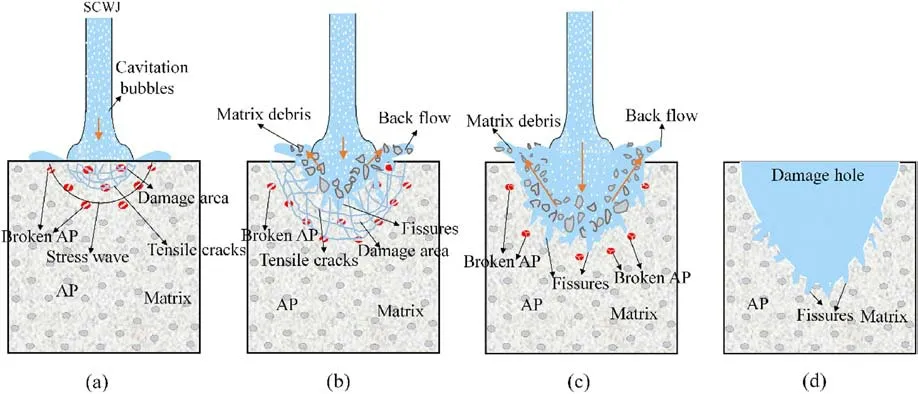
Fig.17.Breaking mechanisms of HTPB propellants under SCWJ impact.
On the other hand, according to the different cavitation modes and calculation (test) conditions, the order of the peak cavitation collapse pressure is generally ranging from 102to 104MPa[43-46],the impact time is a few milliseconds, and the area of action is on the micron scale,as the mechanical force including the wave shock,micro-jet and the high-pressure water jet were impacted on the HTPB propellant equivalently high strain rate [13,47].The content of the binder is relatively high in HTPB propellants.At low strain rates, the whole material usually exhibits typical ductile fracture characteristics due to the viscoelastic (plastic) property of the binder[48].The damage failure modes are mainly the debonding of solid particles,the expansion of holes formed by debonding and the cracking of the binder.However, at high strain rates, the HTPB propellants exhibit typical brittle fracture characteristics [49,50],and the failure modes are mainly nucleation, growth, and polymerization of microcracks.HTPB propellants are viscoelastic heterogeneous material exhibits that become brittle when impacted by a cavitation water jet.However,the surrounding matrix remains elastic,and cracks caused by cavitation water jets will not result in brittle fractures of the entire sample.As the SCWJ continues to impact the matrix and the compressive strength of HTPB propellants decreases due to the shattering of the AP, more cracking forms, and those cracks combine with AP cracking, growth, and then converging fracture, and the damaged area falls off the original matrix by tensile failure.AP particles dissolve in water quickly.
3.3.Failure modes
To sum up, the mechanism of the HTPB propellants breaking process is illustrated in Fig.17.When the SCWJ impacted the surface of HTPB propellants,the stress wave that formed inside the sample[39,41,51] influenced HTPB propellants.The AP particles form intergranular fracture cracks and then crush into smaller particles due to the stress wave,reducing the matrix’s compressive strength to some extent.The stress waves will be reflected and transmitted into the targeted sample resulting in tensile stress and shear stress,resulting in tensile cracks firstly,as shown in Fig.17(a).Because of the stress concentration, the shear cracks formed and the cracks developed.At the same time, the AP dissolves in water, increasing the width of the cracks leading to water entering the cracks due to the water edge effect[39,41,51,52].The crack opens,and the length and width of the crack increase and further expand; those cracks interact, eventually forming tensile-shear cracks, and finally destroying the matrix.The breaking matrix also impacts the SCWJ,forming matrix debris,which is carried out of the crushing area by reflux, and the damaged hole is formed preliminary, as shown in Fig.17(b).As the SCWJ continues to impact,the stress wave and the reflected wave interfere with each other continue, resulting in cracks in the newly damaged area.The cracks develop and interact along the natural underwater pressure,causing further damage,as shown in Fig.17(c).Furthermore,the energy and velocity decrease due to backflow and wall friction in the hole, resulting in a stress concentration less than the tensile and shear strength.Ultimately,as shown in Fig.17(d), the hole depth does not increase, and the new surface only has fissures.
4.Conclusions
This investigation aims to reveal a failure mechanism of HTPB propellants under SCWJ.CT,SEM,and DIC techniques were used to investigate the micro and macro breaking morphology of impacted HTPB propellants, the mechanical change process, and the growth and propagation of cracks.In microscopic morphology change,the Al powder is still encapsulated in the matrix,and AP particles break up firstly, the degree of damage increases with the increase of working pressure,and dissolve in water finally.The collapse of the cavitation bubble impacts the matrix with a high strain rate force.Numerous dense and unevenly sized pores form in the matrix.The AP deforms by cracking and even shattering, decreasing HTPB propellants’ compressive strength.The matrix’s fracture surface is flat and smooth,which relates to its brittle fracture.The DIC and the SEM results reveal that the compressive strain concentration region is located right below the nozzle when the cavitation water jet impacts the HTPB propellants, while the compressive strain increases to 2%and 6%in axial and transverse directions,respectively.The shear strain region distributes symmetrically with the jet axis,increasing to 4% at the first 16th ms at the working pressure of 22.5 MPa.When the impact force exceeds the compressive strength of 4 MPa, two tensile cracks are formed firstly at the compression strain concentrate region, many shear cracks are generated at the shear strain concentration region, and the primary tensile cracks are cut-through finally, forming the tensile-shear cracks, and the matrixes fall off from the sample finally.The failure modes of HTPB impacted by SCWJ are classified as tensile cracks-dominated and tensile-shear cracks-dominated damage mechanisms.Besides, the HTPB propellants formed a breaking hole shaped like a cone after impact 10 s,and the hole’s inner is irregular.The mass loss increases by 17 times at maximum with the working pressure increasing by three times.Meanwhile the damage value of the breaking hole remaining on the surface increased by 7.8 times while 2.9 times in the breaking hole in depth.With working pressure increasing, the number of cracks around damaged holes increase.Working pressures affect breaking efficiency.This study helps to deepen the understanding of HTPB propellants’ erosion patterns under cavitation water jet and provides valuable information for improving breaking efficiency and process parameters optimization.As energetic materials, the safety of the processing process is crucial, and the study of the safety threshold problem under cavitation water jet impact is necessary.
Declaration of competing interest
The authors declare that they have no known competing financial interests or personal relationships that could have appeared to influence the work reported in this paper.
Acknowledgments
This research work was supported by the Program for National Defense Science and Technology Foundation Strengthening, and the Youth Foundation of Rocket Force University of Engineering(Grant No.2021QN-B014).
- Defence Technology的其它文章
- Evolution of molecular structure of TATB under shock loading from transient Raman spectroscopic technique
- MTTSNet:Military time-sensitive targets stealth network via real-time mask generation
- Vulnerability assessment of UAV engine to laser based on improved shotline method
- Free-walking: Pedestrian inertial navigation based on dual footmounted IMU
- Estimation of surface geometry on combustion characteristics of AP/HTPB propellant under rapid depressurization
- Numerical study on the blocking effect of skin on Flash-Ball Impact and damage assessment

