Vulnerability assessment of UAV engine to laser based on improved shotline method
Le Liu , Chengyng Xu , Chngbin Zheng , Sheng Ci , Chunrui Wng , Jin Guo ,*
a Changchun Institute of Optics, Fine Mechanics and Physics, Chinese Academy of Sciences, Changchun 130033, China
b University of Chinese Academy of Sciences, Beijing 100049, China
Keywords:Laser weapon Laser damage Vulnerability UAV Engine Killing probability
ABSTRACT Laser anti-drone technology is entering the sequence of actual combat,and it is necessary to consider the vulnerability of typical functional parts of UAVs.Since the concept of "vulnerability" was proposed, a variety of analysis programs for battlefield targets to traditional weapons have been developed, but a comprehensive assessment methodology for targets’ vulnerability to laser is still missing.Based on the shotline method, this paper proposes a method that equates laser beam to shotline array, an efficient vulnerability analysis program of target to laser is established by this method,and the program includes the circuit board and the wire into the vulnerability analysis category, which improves the precision of the vulnerability analysis.Taking the UAV engine part as the target of vulnerability analysis, combine with the"life-death unit method"to calculate the laser penetration rate of various materials of the UAV,and the influence of laser weapon system parameters and striking orientation on the killing probability is quantified after introducing the penetration rate into the vulnerability analysis program.The quantitative analysis method proposed in this paper has certain general expansibility,which can provide a fresh idea for the vulnerability analysis of other targets to laser.
1.Introduction
As a new type of weapon, laser weapons are gradually used in countering the growing threat of drones due to their light speed engagement,high accuracy of beam pointing and low cost per shot[1,2].However,the industry has been lacking a clear understanding of whether the UAV engine can be used as a suitable part for laser strike.In order to analyze the strike capability of laser to UAV engine, a comprehensive assessment method for the vulnerability of target to laser is indispensable,which also should be applicable to other functional parts of UAVs.Regarding the damage test of laser to the engine, in 2014, the U.S.Navy released information about LaWS burning out the engine of a rigid hull inflatable boat [3]; in 2015,Lockheed Martin used a 30kw laser weapon that cut through the bonnet and seared through the engine block within seconds from 1 mile away [4].UAV engine is partially similar [5,6], which has a complex structure and may also contain vulnerable subparts,such as carburetor,cylinder intake pipes,ignition control lines,and so on.
R.Ball [7] proposed that the vulnerability analysis of target to laser can be compared to the destruction of the non-explosive penetrating object to target, but detailed method was not mentioned.The shotline method was introduced to analyze the vulnerability of target to non-explosive penetrating objects,mainly including parallel equally spaced grid shotline [8-10] and aiming grid shotline [11-13].The shotline method is mainly used in the damage mechanism and vulnerability analysis of battlefield targets to traditional weapons, but it can play a supporting role in the vulnerability analysis of target to laser.In order to analyze the vulnerability of target to laser, Pei Y et al.[14] used an improved system method to evaluate the vulnerability of UAVs to laser based on parallel equally spaced grid shotline.However, the precision of simulation can be further improved by increasing the types of calculation subparts, considering the penetration rate and penetration area.
Based on the shotline method, this paper proposes a methodology to equate the laser to a shotline array, and establishes a vulnerability analysis program by this method.The program can realize the penetration calculation of laser shotline array to various subparts, including special subparts such as circuit boards and wires, which improves the precision of vulnerability analysis.Taking the aviation four-stroke piston engine part as the vulnerability analysis target,the three-dimensional model of the engine and the fault tree model are built, and the laser penetration rate of engine subpart materials can be obtained based on material damage data and "life-death element method".The killing probability of different laser weapon system parameters and strike azimuth are calculated by using the aiming grid shotline method after the model and penetration data are introduced into the vulnerability analysis program of target to laser,and the optimal aiming point of the engine part is analyzed by using the parallel equally spaced grid shotline method and the aiming grid shotline method.
The content of this article is organized as follows: section II mainly introduces the general vulnerability analysis method of target to laser, section III is the application of this method, which analyzes the influence of the laser weapon system parameters and the strike orientation on the engine killing probability, and determines the optimal aiming point of the engine part.Section IV summarizes the strengths of the method and introduces the application prospects of vulnerability analysis.
2.Vulnerability analysis method of target to laser
In order to calculate the killing probability of target to laser, a certain laser aiming point is selected as the center of sphere,and a spherical analysis domain including the target model is established.Generate a laser center shotline in the spherical analysis domain.Taking the laser center shotline as the axis,the laser shotline array in which multiple shotlines are parallel to each other is generated according to a certain arrangement, and the positions of other shotlines in the laser shotline array can be obtained by properly shifting the laser center shotline.In order to save computing resources, the parts that intersect the laser beam are preferentially identified after the laser shotline array is generated.Within these parts, the penetration part numbers of the shotline array are counted.According to the penetration part numbers and the target fault tree model,the laser killing probability to target is calculated.If the target type is known to the defender, it is also necessary to determine the optimal aiming point.
2.1.Establish the position of the laser center shotline in the spherical analysis domain
Select a point on the surface of the spherical analysis domain as the starting point of the laser center shotline.The line connecting the starting point of the laser center shotline and the center of the sphere is the laser aiming line,and the direction of the aiming line vector is the striking direction.In the striking plane perpendicular to the striking direction and through the center of the sphere,multiple laser hit points are randomly generated by using the aiming grid shooting line method.The offset between the laser striking points and the aiming point obeys the normal distribution.The line connecting the starting point of the laser center shotline and the hit point intersects the sphere at another place, and this intersection is called the end point of laser center shotline.As shown in Fig.1 below,establish a local coordinate system x′-y′-z′in the global coordinate system x-y-z of the target model.The center of the sphere is taken as the origin in the local coordinate system, the line of sight is the z′ axis, and the x′-y′ plane is perpendicular to the z′axis.The laser hit points are located in the x′-y′plane,and B is one of the hit points,and its coordinate is(x′i,y′i,0).O is the aiming point, A is the starting point of the laser center shotline, C is the end point of the laser center shotline passing through point B, and R is the radius of the spherical analysis domain.
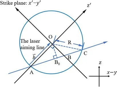
Fig.1.Laser strike target plane geometry.
The coordinates of point B that obey the normal distribution in the local coordinate system represented as:
where φ1, φ2obey (0,1) uniform distribution, σ is the offset variance of the hit point from the aiming point.Select the z axis as the reference vector and express it as: a⇀=[0 0 1].The coordinates of point B that obey the normal distribution in the global coordinate system can be solved by coordinate transformation.
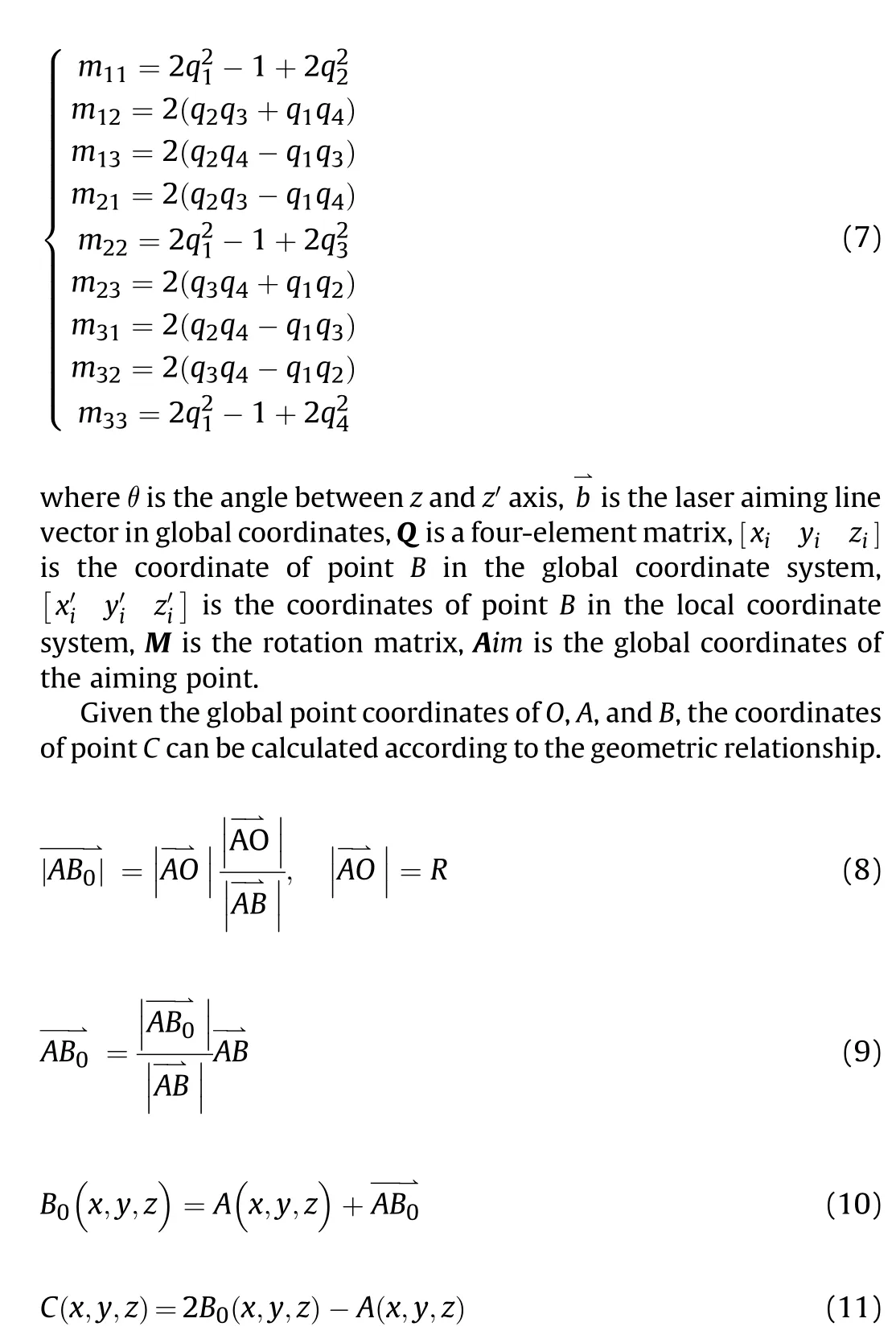
The positions of other shotlines in the laser shotline array can be obtained by properly translating the starting point and the ending point of the laser center shotline in the plane perpendicular to the shotline.Multiple random hit points correspond to multiple sets of laser shotline arrays.
2.2.Arrangement of laser shotline array
Around the center shotline of the laser, multiple shotlines are generated within the ring radius.There are two main types of arrangement of shotline arrays, circular array and square array, as shown in Fig.2.In order to prevent the laser shotline array from staggering some non-shielding parts with small geometric dimensions, the number of the laser shotlines should be properly encrypted considering the constrain of calculation time.When the laser shotline staggers the shielding and geometrically small parts,the parts can be appropriately ignored.In Fig.2(a), the circular array is dense inside and sparse outside, which suitable for Gaussian beams with small radius, but the shotline spacing at the edge of the ring radius is relatively large,and there is a possibility of staggering non-blocking parts;while the square array has the same interval in Fig.2(b),which can reduce the possibility that the laser shotline array at the edge of the ring radius stagger parts, and is more suitable for flat-top laser beam.In the application scenario of ground-based laser,Gaussian beam is affected by tracking jitter and atmospheric effects, and the energy at the center of the spot ring radius is diffused.Therefore,it may be more appropriate to consider the laser beam at the target as a flat-hat beam.According to the beam type, the arrangement of the shotline array is selected, and the coordinates of the start point and the end point of other shotlines in the laser shotline array can be established.
2.3.The intersection recognition of the beam and the part of the target model
The laser shotline array is equivalent to the laser beam,and the intersection of the laser and the part can be regarded as the intersection of the laser array and it since the laser beam has a certain diameter.The surface of the part in the target model can be split into a large number of planar triangles [15], and the area method is usually used to judge whether the intersection point of the laser shotline and the plane triangle is located in the plane triangle [16].However, it is different when the laser intersects the plane triangle,as shown in Fig.3.To save computing resources,the number of the triangle passed by the beam and the part number of the triangle are counted preferentially.Within these parts, count the parts that the shotline passes through again,which can reduce the calculation time to determine whether the shotline passes through other parts.
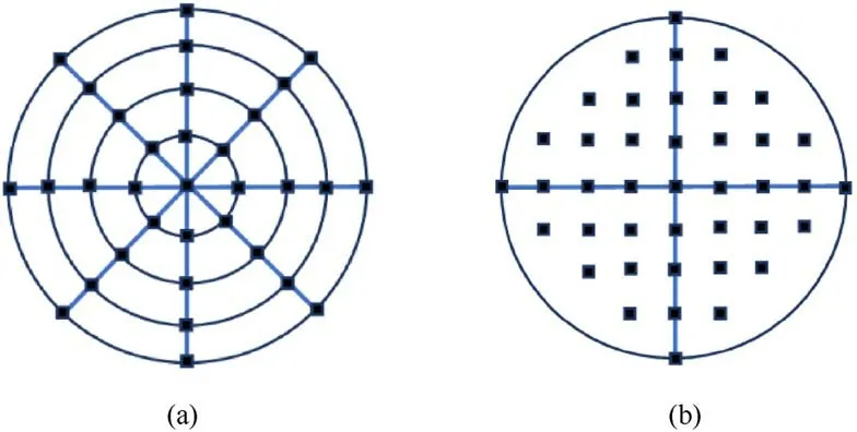
Fig.2.Array arrangement of laser shotline: (a) Circular array; (b) Square array.

Fig.3.Penetration recognition of plane triangles: (a) Single shotline through planar triangle; (b) Laser passing through planar triangle.
As shown in Fig.3(a), a point inside the plane triangle is the intersection point of the shotline in a certain part.Assuming that the area of the triangle is S, the areas of the triangles enclosed by the intersection points and the vertices of the triangle are S1,S2and S3,respectively.The area method usually is used to judge whether the shotline passes through the plane triangle,and the condition is:
If the intersection point is outside the plane triangle, the condition is:
When the laser passes through a plane triangle, select the centroid of the triangle surface, project the centroid point to the three sides of the triangle surface,and calculate the coordinates of the projected point.The three edges of the triangle are translated 2r distance along the projection direction to obtain the rectangular region outside the triangular region, and the sector region is obtained by connecting the vertices of the rectangular region, as shown in Fig.3(b).r is the ring radius of the laser.The rectangular region and the sector region are called the outer ring of the triangle.When the intersection of the laser center shotline and the target model is located in the plane triangle or the outer ring, it can be considered that the beam passes through the plane triangle and the part to which the plane triangle belongs.There are three situations in which the laser beam passes through the plane triangle:
(1) When the laser center shotline passes through the plane triangle, and the area method is also used as the judgment condition;
(2) When the laser center shotline passes through the rectangular region,the judgment condition is whether the distance from the spot center point to a side of the triangle is less than r;
(3) When the laser center shotline passes through the sector region,the judgment condition is whether the distance from the spot center point to a vertex of the triangle is less than r.
2.4.Penetration statistics for parts
Sort the intersection points of the shotline and multiple plane triangles by vector length.The vector is from the starting point of the shotline to the intersection point of the shotline and the plane triangle,and ensure that the shotline has two situations of entering and exiting in all parts.As the laser shotline enters or exits the model part,the difference between the lengths of the vectors is the thickness of the part that the shotline passes through.Knowing the penetration rate of the normal incident part of the laser and the angle between the laser center shotline and the plane triangle,within a given laser irradiation time, the parts penetrated by all shotlines in the shotline array can be counted.Uniqueize the penetration part number of all shotlines in the shotline array to obtain the penetrating parts of the laser shotline array.The penetrating area is the product of the ratio of the number of shotlines penetrating the part to the total number of shotlines in the laser shotline array and the spot ring area.
The circuit board is a commonly used part.It is assumed that the side where electronic components are soldered is the front side,and the opposite side is the back side.When the laser irradiates the front side, the circuit board is immediately damaged; when the laser irradiates the back side, the laser must penetrate the circuit substrate to be considered damaged.Meanwhile, the wire in the target model is also a common part, which can be regarded as a series of points since it is relatively small,and the influence of the wire on the shotline penetration depth can be ignored.If there is a point inside the beam, project that point on the nearest shotline inside the beam.If the projection point is within the shotline penetration depth and the sum of the part penetration time from the starting point of the shotline to the front of the wire and the penetration time of the wire protection material is less than the laser irradiation time, it is determined that the wire is damaged.When the laser penetrates the protective material of the wire, it will cause flammable material inside the wire to catch fire,and the wire will be damaged instantly,so there is no need to consider the spatial distribution of the sub-wires inside the wire.
2.5.Calculate target model killing probability and determine the optimal aiming point for the target
Making the laser hit a certain aiming point multiple times,and count the number of parts penetrated by the laser shotline array in each beam and the penetration area corresponding to the parts penetrated.Assuming the part killing probability, according to the fault tree definition, the killing probability of a certain laser to the target can be calculated.
where PKis the killing probability of the target model, which can quantitatively describe the laser damage efficiency under different conditions, m is the number of laser random strikes, Pik/his the killing probability of a single laser on the target model which depends on the functional logic relationship between the parts in the fault tree model [17], SUMi/mis the number of times the part i penetrated under m random laser strikes, Piis the penetration probability of the part,which can be used as an analysis parameter of the target model’s killing probability.
In order to determine the optimal aiming point,the strike plane can be divided into area units by using the parallel equally spaced grid shotline method,and the center of each area unit is used as the laser hit point to obtain multiple best killed area units.Take the center of each best killing area unit as a new aiming point, and generate multiple laser hit points again.The hit point follows a normal distribution relative to the new aim point.Compare the killing probability of different aiming points and determine the optimal aiming point after repeating the above steps.
3.Vulnerability analysis of aviation piston four-stroke engine to laser
Based on the 3D modeling software, the aviation four-stroke piston engine of the small and medium-sized UAV is simplified,and the non-shielding wires are segmented to form a wire point set.Assume that the laser is the flat-top laser beam, and the laser shotline array is the square array.The model data and the penetration data of the flat-top laser beam are introduced into the vulnerability analysis program of target to laser,where the target of the vulnerability analysis is the engine part,and the identified and statistical part are actually subparts in the engine part.The influence of laser weapon system parameters, strike orientation, and aiming point selection on the engine killing probability can be analyzed in the program.
3.1.Engine simplified model and fault tree diagram
The piston engine is mainly composed of cylinder, piston, connecting rod, crankshaft, valve mechanism and casing.The engine needs to go through four strokes to complete a working cycle.In addition to the main subparts, the engine must have several auxiliary subparts to work with it, such as spark plug, carburetor,ignition coil, and camshaft, etc.[18].When the laser is used as a lethal weapon,wires connecting non-shielding subparts cannot be ignored.This article considers connecting the ignition control wires,and ignoring the wires connecting the generator,the electric motor and other obstructed subparts.Negligible wires are not drawn in Fig.4.
Piston engines are usually divided into two types:air-cooled and water-cooled.For the air-cooled type, it has many heat sinks, the equal volume method can be used to simplify the cylinder into a cylindrical shell;for the water-cooled type,the cooling water needs to be considered.The effect of cooling water on temperature can be corrected by using the existing calibration law model [19].This article takes the air-cooled engine as the target for vulnerability analysis,and its simplified model is shown in Fig.4.The engine part model is split by subparts,the number of subparts is 95,and Details of the subparts are given in Table 1.The sum of the plane triangles of all subparts is adjusted to 50,000,and the triangulation diagram are given below.
In Table 1, D′stands for radial thickness, D′′stands for axial thickness, D1stands for outer diameter, D2stands for inner diameter,H stands for height,Listands for length of cuboid i, Wistands for width of cuboid i,l stands for path length,R stands for radius of curvature, RAD stands for radian value.
In the process of vulnerability analysis, the kill probability of subparts is always a difficult problem to resolve.It can only be determined based on a large number of underlying experimental data,and may need to be graded further down.But the influence of subpart damage on engine kill probability in this paper mainly comes from the damage analysis of UAV and the working principle of engine.The criterion of engine damage is that the UAV crashed in a short period of time,regardless of the failure of the UAV’s combat mission due to damage to the subparts.During the flight of the UAV,due to the partial loss of power, the lifting force and gravity of the UAV that originally flew at a constant speed could not balance [6],which may eventually result in instability and crash of the UAV.The kill probability of the engine can also be taken into account to depend on the amount of power loss actually,and the power of the engine is supplied by the drive units.
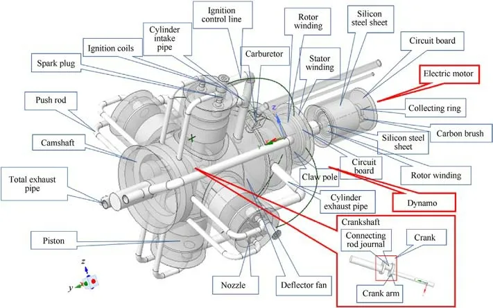
Fig.4.Simplified model of aviation four-stroke piston engine.
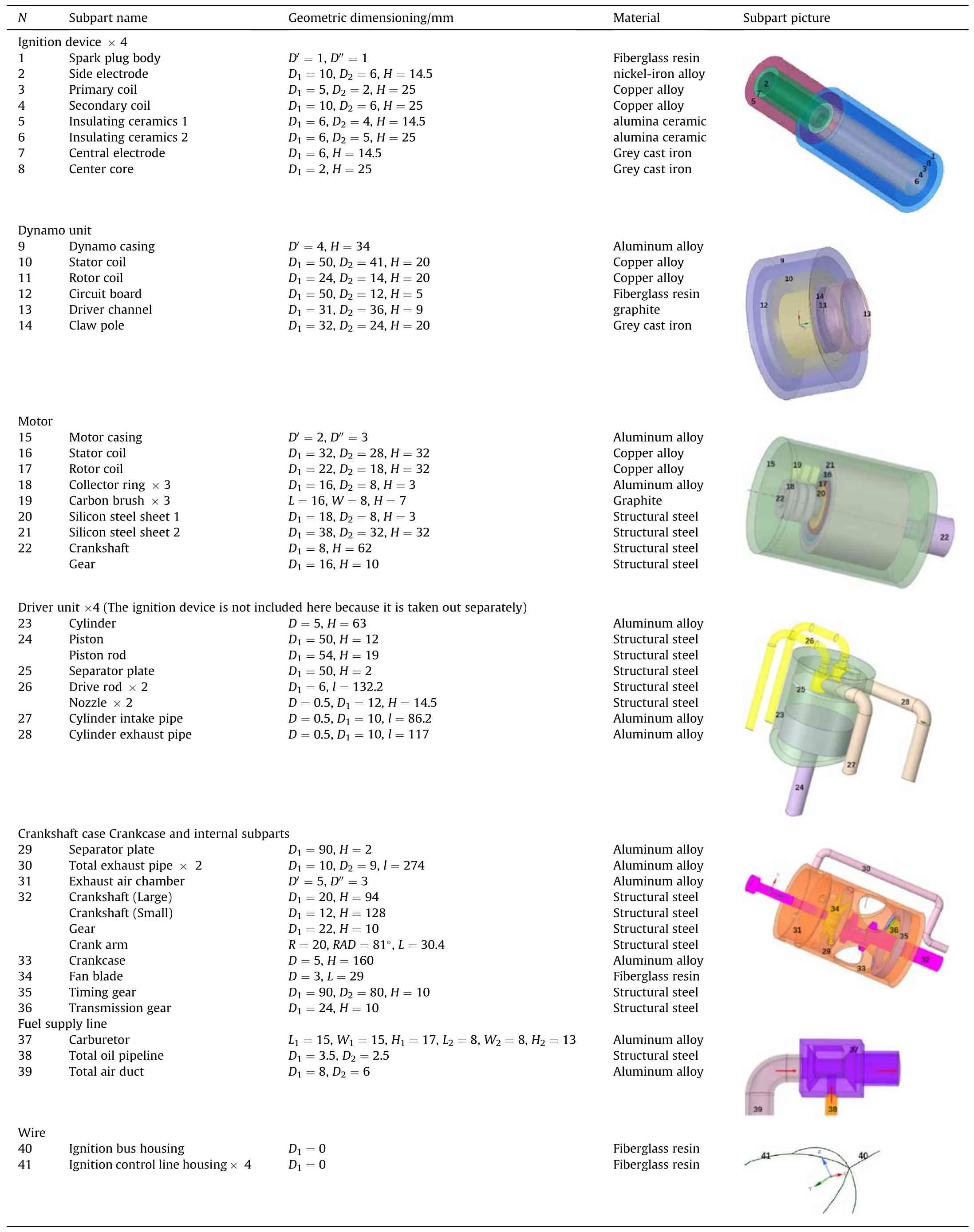
Table 1 Subpart details of aviation four-stroke piston engines.
Aviation piston four-stroke engine has 4 drive units in this paper,assuming that one is damaged,the engine killing probability is 0.25;if two drive units are damaged,the killing probability is 0.5;if three drive units are damaged,the killing probability is 0.75;and if four drive units are damaged,the killing probability is 1.When the lethal subparts are damaged,the engine killing probability is also 1.All others are obscuring subparts, and obscuring subparts damage does not affect the power generated by the engine,but it will affect the laser hit time on non-obscuring subparts.Once a subpart is penetrated, it is considered damaged, so the killing probability of the subpart is either 0 or 1, regardless of the possible incomplete damage.The criteria of lethal, obscuring and non-lethal nonobscuring subparts are mainly derived from the working principle of the engine and damage analysis,and the specific details are given in Table 2.The fault tree of an aviation four-stroke piston engine is shown in Fig.5.
In Fig.5, there are four vote gates between drive units damage and the non-lethal non-obscuring subparts damage.Since the extent of the engine damage is unknown when the engine damage occurs, or the number of drive units damage is unknown, use four vote gates instead of one joint gate can determine the number of drive units damage according to the channel signal of 4 vote gates,and then the number signal of drive units damage is transmitted to the killing probability calculation module.For example, if three drive units are damaged, the vote gates numbered 3 and 4 are opened,and the minimum number 3 is identified as the number of drive units damage in the vulnerability analysis program.In addition, it should be noted that all the drive units are consistent, so they are omitted,and the damage to other obscuring subparts will not affect the killing probability of the engine,so they are not in the fault diagram.
3.2.Penetration rate of different materials
In the target to laser vulnerability analysis program, the different subpart materials may vary,as shown in Table 1.In order to calculate the laser penetration rate of different subparts, the fitting equations of the laser penetration rate of 8 materials to different laser power densities are introduced,including aluminum alloy materials, fiberglass resin composite materials, structural steel materials, copper Alloy materials, grey cast iron materials,alumina ceramic materials,nickel-iron alloy materials and graphite materials.Composite materials are set based on literature data[20];penetration data of non-composite materials are calculated by the"life-death unit method".Assuming that the reflectance of metal materials in the near-infrared band is 0.7, and the reflectance of non-metal materials is 0.3,a uniform circular surface heat source is loaded on a flat plate of different materials with a thickness d of 5 mm,and the radius r =2 cm,as shown in Fig.6.Neglect the small amount of energy loss due to thermal radiation and convection,according to the isotropic heat conduction formula of the material,and the temperature field of the plate at time t is calculated.
where T(x,y,z;t)represents the temperature field at time t,ρ,c and λ represent the density, specific heat and thermal conductivity of the material respectively, ˙Qlaseris the laser surface heat source;xiis the position in a certain direction.When the surface temperature of the material reaches the melting point,the unit is killed,so that the surface heat source of the laser is loaded to the surface of the next layer, and so on, until it is penetrated [21-23].Given the penetration time, the ratio of thickness to penetration time is the penetration rate of the materials.In actual combat, due to multiple influences such as gravity and tangential airflow,the melted liquiddroplets can fall off quickly, regardless of the enthalpy and liquid vaporization during phase transition.
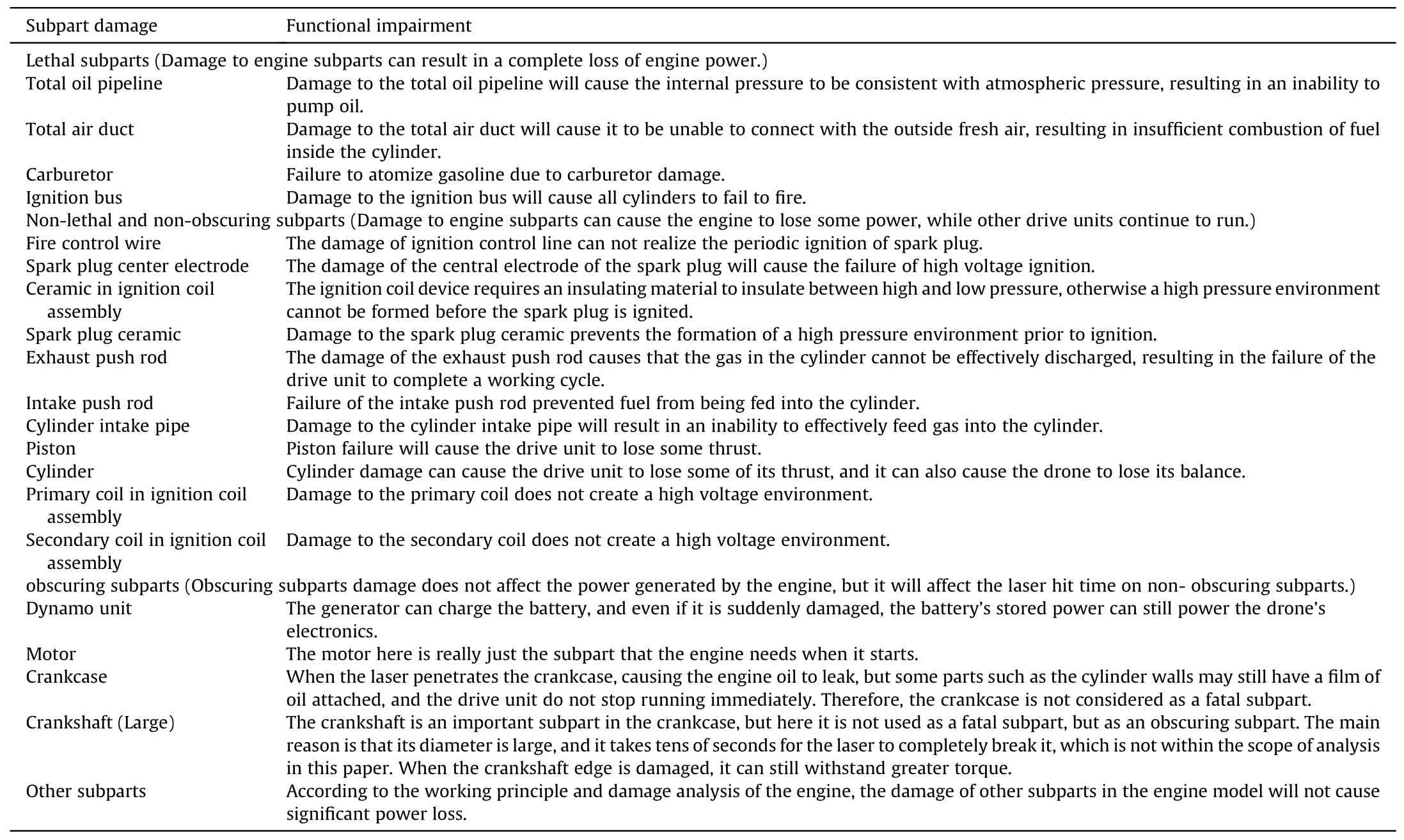
Table 2 Analysis of functional damage of subparts.
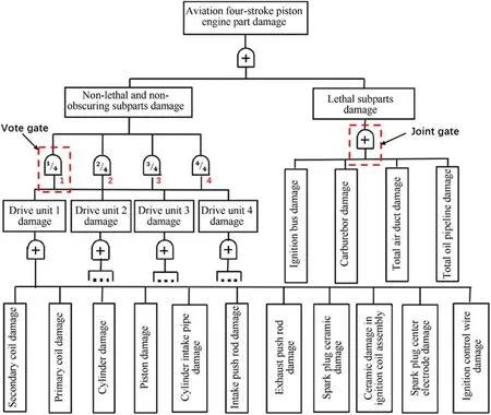
Fig.5.Fault diagram of aviation four-stroke piston engine.
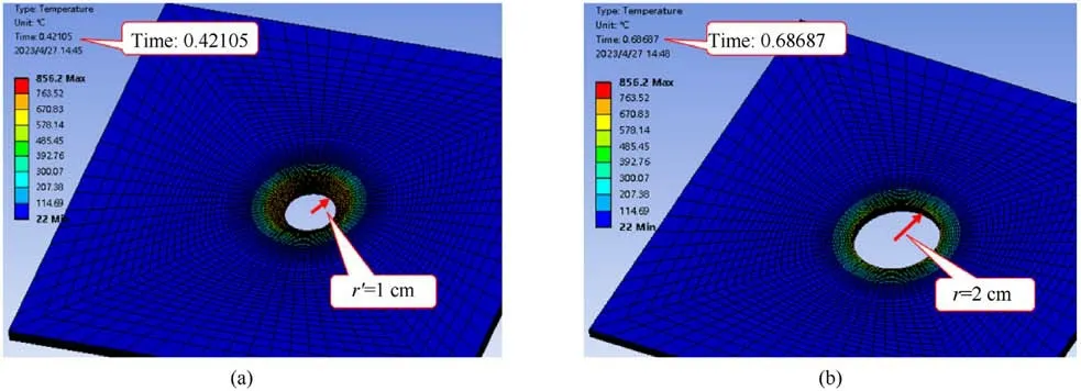
Fig.6.Perforated morphology of aluminum alloy plate at different times: (a) Penetration moment at center of spot; (b) Penetration moment at edge of spot.
Due to the energy loss at the edge of the spot caused by heat conduction, the laser penetration rate needs to be corrected appropriately.The depth of penetration at the edge of the spot depends on many factors, including material, laser power density,and irradiation time, etc.When the laser irradiates the aluminum alloy material,and the power density is 2 kW/cm2,the penetration rate in the central area of the spot invariable,and the radius of this area is r′= 1 cm.According to the penetration time of the center area of the spot and the edge area,the penetration rate at the edge is about 0.6 times of the penetration rate of the center area of the spot.0.6 is also the height of the relative peak of the standard normal function at one variance.Therefore,when the spot radius is greater than 1 cm,the penetration rate curve at the edge of the spot is approximately one side of the standard normal distribution curve,as shown in Fig.7.In the vulnerability analysis program,the penetration rate is the average penetration rate within the diameter of the beam.
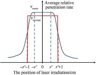
Fig.7.Analysis diagram of beam average penetration rate.
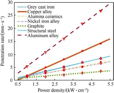
Fig.8.Linear fitting of average laser penetration rate of different materials.
where vcenteris the penetration rate of spot center area,tpeneis the penetration time of spot center area; r′is the radius of the center area of the spot;vaverageis the average penetration rate of the beam.When the spot diameter is larger, the average penetration rate of the beam will be closer to the penetration rate of the center of the spot.Since the material of the engine subparts is mostly aluminum alloy, the edge penetration rate curves of other materials are approximated with the same curve.
The simulation calculation results of different materials show that the linear fitting results of the laser penetration rate to different laser power densities are great,as shown in Fig.8.When the penetration rate is negative, its value is zero.The linear fitting coefficients are shown in Table 3.
In the actual laser strike process, due to the complexity of the model and the size of the laser spot, there may be many complex situations where the laser beam intersects with the model, as shown in Fig.9.
Fig.9(a) is the simplest and most common situation, when the laser is obliquely incident, the angle between the laser beam direction and the normal direction of the plane is θ, and the laser power density is I0cos(θ).In Fig.9(b), the direction of the laser beam and each irradiation surface has a corresponding irradiation angle,and the power density of the laser is expressed as I0cos(θi),where θiis the angle between the normal direction of each intersection plane and the direction of the laser beam.Ignore the situation that the energy transferred from the center of the spot to the edge is hindered due to the edge.In Fig.9(c),when part of the laser irradiates the surface of the subpart, the laser energy loss due to heat conduction outside the cylindrical beam area will be reduced,so the penetration rate of the laser shotline array will be slightly greater than that of the first a situation.In order to simplify the complexity of the vulnerability analysis, all intersections of the laser and the model are set as the situation in Fig.9(a).
3.3.Boundary condition setting for vulnerability analysis
The aviation four-stroke piston engine is a typical functional part of the UAV, and its optimal aiming point may not be known before the strike.Therefore, this paper takes the centroid of the engine model as the aiming point (sphere center) to establish a spherical analysis domain.The laser can randomly strike 100 times along a certain strike direction towards the aiming point to evaluate the killing probability of a single laser strike,and the deviation between the hitting point and the aiming point obeys the normal distribution.The triangulation model and laser strike model in the vulnerability program are shown in Fig.10.The boundary conditions of engine vulnerability analysis are shown in Table 4.
The laser power density and ring radius in Table 4 are affected by laser power, beam quality, atmosphere, tracking accuracy, and instrument jitter,etc.They are the laser power density and ring radius after being time-averaged.The azimuth in the table is the angle between the projection of the laser on the x-y plane and the x axis,and the pitch angle is the angle between the laser shotline and the x-y plane.
3.4.Analytical results of vulnerability of engine to laser
3.4.1.Influence of laser weapon system parameters on killing probability
Assuming that the laser power is 100 kW, if the ring radius where the power accounts for 0.83 of the target power is 2 cm,it is estimated that the power density of the spot is about 6 kW/cm2.After being reflected by the surface of different materials,the laser power density is still guaranteed to be on the order of several kW/cm2, which is sufficiently lethal to the shell of composite ormetal subparts [24-26].According to actual scenarios, laser weapons need to shoot down targets within seconds.Therefore,the range of laser power density in this paper is 2-8 kW/cm2,the laser irradiation time is 2-8 s,the radius of the laser spot is 1-3 cm.The ring radius is several centimeters, which places high demands on the beam control system.Its size mainly depends on the laser wavelength, emission aperture, beam quality, tracking jitter, atmospheric environment and compensation system, etc.[27,28].According to the above assumptions, the laser power density,irradiation duration and ring radius were changed respectively,and the influence of different laser weapon system parameters on killing probability was analyzed, which are shown in Fig.11.

Fig.9.Various intersection situation of laser beam and model: (a) Oblique incidence; (b) Laser irradiation edge; (c) Partial occlusion of the laser.
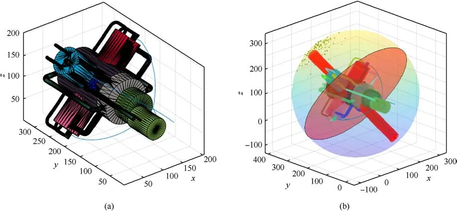
Fig.10.Vulnerability analytical model of engine to laser: (a) Triangulated model of the engine; (b) Laser strike model.

Table 4 Boundary conditions for engine vulnerability analysis.
As shown in Fig.11, increasing the laser power density, irradiation duration,and ring radius can increase the killing probability,but there are significant differences in the degree of improvement.Under the conditions of taking into account the power supply of the equipment and the multiple indicator requirements of the beam control system,when the laser power density is 6 kW/cm2and the irradiation time is 5 s, the laser weapon has a relatively high costefficiency ratio.It can not only ensure the laser damage efficiency,but also avoid the excessive consumption of electric energy of the laser weapon.Fig.11(c) shows that laser weapons not only pursue high laser power density,but also appropriately relax to the size of the ring radius where the power accounts for 0.83 of the target power under the condition of keeping the power density constant.
3.4.2.Influence of laser strike azimuth on engine killing probability
Air targets are usually struck in an upward-sloping direction in ground-based laser strike scenario.Therefore, in the vulnerability analysis,representative laser strike pitch angles are selected,which are 30°, 45°and 60°respectively.Change the laser strike azimuth,keep the other parameter settings consistent with Table 4, and analyze the killing probability of the laser at different strike azimuths.The killing probability is shown in Fig.12.

Fig.11.Influence of laser weapon system parameters on killing probability: (a) The effect of power density on the killing probability; (b) The effect of irradiation duration on the killing probability; (c) The effect of ring radius on the killing probability.
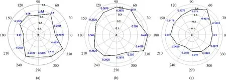
Fig.12.Influence of laser strike azimuth on killing probability:(a) The killing probability of different azimuths when the pitch angle is 30°;(b)The killing probability of different azimuths when the pitch angle is 45°; (c) The killing probability of different azimuths when the pitch angle is 60°.
The azimuth of 330°and the azimuth of 180°are the laser strike azimuths with the maximum and minimum killing probability respectively in Fig.12(a).When the azimuth is 330°, the main reason for the higher probability is that the lethal subpart carburetor and a certain ignition coil wire are closer to the laser aiming line,resulting in a higher penetration probability of the subpart.In Fig.12(b),the azimuth 300°and azimuth 330°are the laser striking azimuths with the maximum and minimum killing probability respectively.When the azimuth is 330°, the main reason for the higher probability is that the total oil pipeline and the total intake pipe are more likely to be penetrated.When the azimuth is 300°,the laser aiming line is away from the center of all lethal subparts and the two ignition control wires at the bottom of the engine.In Fig.12(c),the azimuth of 60°and the azimuth of 240°are the laser strike azimuths with the maximum and minimum killing probability respectively.When the azimuth is 60°, the main reason for the higher probability is that the laser aiming line is closer to the center of all lethal subparts, and there is a probability of 0.11 that two drive units at the bottom of the engine fail simultaneously under a single beam strike.The killing probability is the second maximum value when the azimuth is 90°.In this orientation, the laser aiming line is far away from deadly subparts,and it is difficult to cause damage to the carburetor,the total intake pipe,the total oil pipeline and ignition control wires.The main reason is that there is a higher probability of two drive units at the bottom of the engine failing simultaneously under a single laser strike, and the probability is 0.39.Comparing killing probability in all the abovementioned azimuths, it is obtained that killing probability is the highest when the pitch angle is 30°and the azimuth is 330°.
3.4.3.Effect of aiming variance on engine killing probability
Assume the aiming error angle of 15 μrad.The offset of the laser hit point relative to the aiming point obeys the normal distribution in the strike plane after the laser travels 3000 m.Its double variance is assumed to be the product of the laser travel distance and the aiming error angle.Select the aiming error angle as 5-35 μrad,and keep the other parameter settings consistent with Table 4, the killing probability is shown in Fig.13(a).The analysis diagram of the killing probability is shown in Fig.13(b), where the radius of the circular solid line is twice the variance corresponding to different aiming angles,and the inside of the circular dotted line is the laser shotline array.
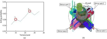
Fig.13.Effect of aiming error angle on killing probability:(a)Killing probability under different aiming error angles; (b)Analysis diagram of killing probability at different aiming angles.
The results in Fig.13(a)show that the killing probability has an upward trend within 5-35 μrad of the aiming error angle, but when the aiming error angle is 10 and 25 μrad, the killing probability suddenly increases, and the main reason for the sudden increase is the star-shaped distribution of different drive units.There is a high probability that a single laser beam will cause the drive unit 3 and the ignition control line of the drive unit 4 to fail simultaneously when the aiming error angle is 10 μrad, and the probability is 0.42,as shown in the laser strike position numbered 1 in Fig.13(b).There is a certain probability that a single laser beam will cause two different numbers of drive units to fail at the same time when the aiming error angle is 25 μrad,and the probability is 0.33,as shown in the laser strike position numbered 2 in Fig.13(b).When the aiming error angle is greater than 30 μrad and 35 μrad,the simultaneous failure probability of two drive units with different numbers caused by a single laser beam will be relatively reduced, and the probabilities are 0.26 and 0.20 respectively.Therefore, the killing probability is the highest when the aiming error angle is 25 μrad.The trends indicate that there are large differences in the killing probability of the engine when it is struck at different positions.
In order to determine the optimal aiming point of the engine,the parallel equally spaced grid shotline method is used to divide the area unit on the strike plane.Since the ring radius is 2 cm,the length and width of the area unit are both set to 2.828 cm.The total number of area units is 121, and each area unit corresponds to a laser beam, as shown in Fig.14(a).
Fig.14(b)contains multiple best killed area units with an engine killing probability of 1 under the hit condition.Taking each center of these area units as a new aiming point, according to the parameter settings in Table 4, the No.79 area unit has the highest killing probability after multiple random strikes in the same manner as above,and the value is 0.93.The center of the No.79 area unit is the best aiming point under the conditions in Table 4.
Taking the centroid of the aviation four-stroke piston engine as the aiming point, when the laser power density is 6 kW/cm2and the irradiation time is 5 s,and other parameters meet the premise of Table 4, the laser weapon system has a relatively high costefficiency ratio; when the laser attack azimuth pitch angle is 30°,and the azimuth is 330°, the laser weapon has the highest killing probability of the engine; Reducing the laser aiming error angle cannot improve the engine killing probability,which indicates that the centroid of the engine model is not the optimal aiming point.In order to improve the engine killing probability,the optimal aiming point is selected as the new aiming point,and the killing probability can be significantly improved.
4.Conclusions
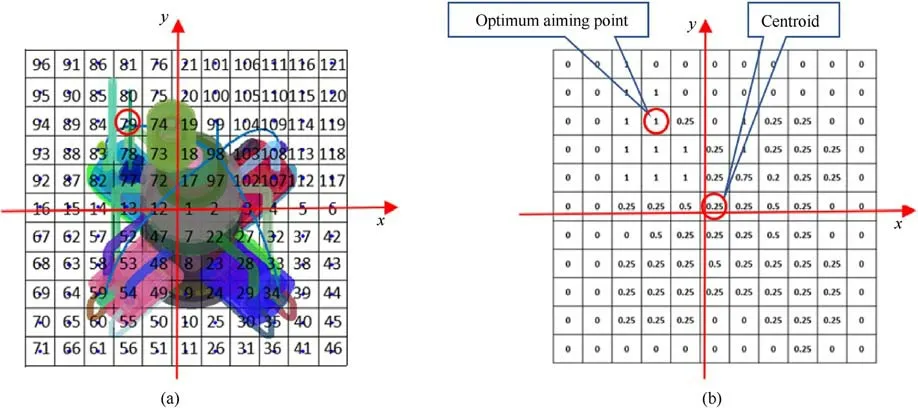
Fig.14.The parallel equally spaced grid shotline model: (a) Area unit number of the strike plane; (b) Engine killing probability of area units under hit conditions.
In order to evaluate the combat application potential of laser anti-medium and small UAVs, this paper proposes an improved vulnerability analysis method of target to laser based on the shotline method.The laser shotline array is equivalent to the laser beam, and the part or sub-part penetration recognition algorithm of the laser shotline array is provided, which increases the equivalent accuracy of the laser; Taking the aviation four-stroke piston engine,which is a typical functional part of the UAV,as the analysis target, the engine part is relatively finely modeled, including the circuit and circuit board in the model,which improves the precision of the vulnerability analysis; Based on material damage data and"birth-death element method", the laser penetration rate of different materials is obtained,which makes up for the lack of laser penetration rate equations for different materials.
Establishing the vulnerability function of UAVs and typical functional parts in future, which can ensure the fineness of the target model, then the vulnerability analysis results of small and medium-sized UAVs to laser will be more convincing than those using traditional geometric equivalents for UAVs.The results of the vulnerability analysis can optimize the parameters of the laser weapon system, select the appropriate laser strike azimuth, and establish the best aiming point of the target,which could effectively improve the combat effectiveness of the laser weapon.Moreover,the vulnerability analysis method of target to laser has a certain general expansibility, and it can also provide new ideas for the vulnerability analysis of other targets to laser.
Declaration of competing interest
The authors declare that they have no known competing financial interests or personal relationships that could have appeared to influence the work reported in this paper.
Acknowledgements
The authors would like to acknowledge National Natural Science Foundation of China (Grant Nos.62005276, 62175234) and the Scientific and Technological Development Program of Jilin, China(Grant No.20230508111RC) to provide fund for this research.
- Defence Technology的其它文章
- Evolution of molecular structure of TATB under shock loading from transient Raman spectroscopic technique
- MTTSNet:Military time-sensitive targets stealth network via real-time mask generation
- Free-walking: Pedestrian inertial navigation based on dual footmounted IMU
- Investigation of hydroxyl-terminated polybutadiene propellant breaking characteristics and mechanism impacted by submerged cavitation water jet
- Estimation of surface geometry on combustion characteristics of AP/HTPB propellant under rapid depressurization
- Numerical study on the blocking effect of skin on Flash-Ball Impact and damage assessment

