Design and Implementation of Nonlinear Precoding for MIMO-SDMA Toward 6G Wireless
Chaowu Wu,Yue Xiao,Shu Fang,Gang Wu
National Key Laboratory of Wireless Communications,University of Electronic Science and Technology of China,Chengdu 611731,China
Abstract: In this paper,we present a novel and robust nonlinear precoding(NLP)design and detection structure specifically tailored for multiple-input multipleoutput space division multiple access(MIMO-SDMA)systems toward 6G wireless.Our approach aims to effectively mitigate the impact of imperfect channel estimation by leveraging the channel fluctuation mean square error (MSE) for reconstructing a highly accurate precoding matrix at the transmitter.Furthermore,we introduce a simplified receiver structure that eliminates the need for equalization,resulting in reduced interference and notable enhancements in overall system performance.We conduct both computer simulations and experimental tests to validate the efficacy of our proposed approach.The results reveals that the proposed NLP scheme offers significant performance improvements,making it particularly well-suited for the forthcoming 6G wireless.
Keywords: MIMO-SDMA;nonlinear precoding;Tomlinson-Harashima precoding (THP);vector perturbation(VP)
I.INTRODUCTION
Multiple input multiple output(MIMO)is a key technology in modern wireless networks that effectively improves system capacity and spectral efficiency [1].In the physical layer specifications of 5G new radio(NR),MIMO is equipped with a large number of antennas,referred to as massive MIMO,to further enhance system throughput [2].As the demand for 1000x increased data rate continues towards 6G communication,MIMO remains one of the most important transmission technologies [3–5].Despite its ability to significantly improve spectral efficiency and transmission performance,MIMO introduces serious interchannel interference (ICI).To address this problem,MIMO precoding [6] was proposed as a transmitterside solution to eliminate ICI.
Naturally,precoding has emerged as a valuable technique for preprocessing transmitted signals in order to achieve enhanced spectral and power efficiency within space division multiple access (SDMA) systems,which has gained considerable attention in recent years.While multiple antenna technology has already demonstrated its potential for improving performance in prevalent multiple access schemes such as time division multiple access(TDMA)and code division multiple access(CDMA),SDMA takes advantage of the spatial transmission flexibility enabled by multiple antennas.By employing precoding to mitigate multi-user interference in SDMA,the spatial resources inherent in multiple antenna technology can be effectively utilized,leading to efficient reuse of timefrequency resources.Moreover,this approach offloads processing complexity from mobile terminals to the base station,simplifying mobile device design.However,achieving optimal segregation and differentiation of users in SDMA requires an infinite number of antennas and radio frequency chains,presenting a significant challenge for present SDMA systems.Therefore,in future wireless communication systems,it is crucial to address pressing issues related to optimize precoding design and efficiently manage SDMA multi-user interference,while effectively leveraging base station resources.These considerations play a vital role in advancing the performance and capabilities of SDMA systems in upcoming wireless communication deployments.
To provide further insights,linear precoding (LP)algorithms commonly used in 5G communication systems include zero-forcing (ZF) [7],minimum meansquared error (MMSE) [8,9],and block diagonalization (BD) precoding [10].While LP is relatively straightforward to implement,it may not achieve optimal throughput.To address this issue,nonlinear precoding (NLP) techniques have been developed.One of the initial NLP techniques introduced was the dirty paper code (DPC) [11],which can perfectly eliminate inter-carrier interference when all additive interference is known at the transmitter.However,DPC exhibits high computational complexity,while perfect channel state information(CSI)at the transmitter may not be practical.To overcome these limitations,simplified NLP techniques such as Tomlinson-Harashima precoding(THP)[12,13]and vector perturbation(VP)precoding [14] have been devised,offering improved performance while reducing complexity.
Specifically,THP stands as a representative example of NLP technology,utilizing nonlinear successive interference cancellation (SIC).The underlying principle of THP involves eliminating continuous interference through a decision feedback structure.By employing a combined modulo operation,the precoded signal is remapped onto the input signal constellation,preserving the transmit signal’s energy efficiency.VP precoding,on the other hand,aims to further reduce transmit power and enhance the signal-to-noise ratio(SNR)at the receiver,leading to performance improvements.This technique introduces perturbation vectors to the transmitted signals for modulation at the transmitter.The receiver then eliminates the introduced perturbation vector through a simple modulo operation,allowing for a decision to be made based on the received symbol.
While standardized precoding schemes are wellestablished in wireless communications,the design of multi-antenna precoding in SDMA systems still faces unresolved challenges in the context of 5G and 6G[15,16].Specifically,the inherent channel orthogonality is inadequate,and the interference among users remains substantial,leading to a noticeable performance gap between traditional digital precoding approaches and the upper bound of system capacity.Consequently,nonlinear precoding has gained significant attention as a potentially effective technique for improving MIMO performance in future generations of NR.For example,the Third Generation Partnership Project (3GPP) has recognized the importance of interference cancellation techniques,particularly at the transmitter end,for co-scheduled user ends (UEs),in achieving these goals [17].Therefore,NLP stands as one of the candidate techniques identified by NR for this purpose,including approaches such as DPCbased,VP-based,and other linear/nonlinear hybrid precoding techniques.
Building upon the existing 5G architecture,NLP schemes for multi-user (MU) transmissions represent one of the potential techniques to enhance the performance of 6G networks compared to LP.However,the practical implementation of NLP faces several technical challenges [18].Firstly,the utilization of large antenna arrays at the base station (BS) in 5G NR results in high complexity and significant overhead.Secondly,as NLP relies on accurate CSI to mitigate noncausal interference,it is more susceptible to CSI errors compared to LP.Thirdly,the receiver design for NLP involves the use of modulo operations and receive combining at UEs,which introduces additional interference from traditional equalization techniques.Furthermore,despite its potential advantages,the performance of NLP under the 5G NR framework falls short of the ideal performance achievable,thereby limiting its practical applicability.Consequently,addressing these challenges remains an urgent and critical problem that requires resolution.Specifically,researchers in [19–21] considered robust NLP structures with imperfect CSI.In[19],the authors proposed two types of multi-branch THP(MB-THP)structures that employ multiple transmit processing and ordering strategies along with a selection scheme to mitigate interference.In [20],the authors proposed the MB-THP transceiver design for MIMO relay systems with amplify-and-forward protocols,which employs successive interference cancellation on several parallel branches.In [21],the authors proposed rate-splitting THP (RS-THP) schemes along with stream combiners to increase the robustness of systems.These approaches focus on NLP structure design for enhancing the robustness against channel inaccuracies.Nevertheless,there is potential for further improvement in NLP by considering channel characteristics and modulo structures.
In this paper,we aim to tackle two fundamental issues in applying NLP to MIMO-SDMA,as CSI sensitivity and receive processing.Specifically,to enhance the robustness of NLP,we consider compensating for channel estimation errors in the developed approach.Additionally,we simplify the receiver structure to eliminate the need for equalization,making downlink transmission more efficient.Therefore,the proposed method includes a robust NLP matrix designed for imperfect CSI acquisition at the transmit side,with a simplified receiver structure free of equalization at the receiver side,fully addressing the initial design problems of NLP.We then demonstrate the potential of NLP to outperform conventional LP for enhancing performance in NR structures.
The remainder of this paper is structured as follows.Section II presents a review of typical NLP schemes.Section III introduces a channel error compensation scheme for NLP.Then Section IV details an interference alleviating receiver as well as the performance analysis.Section V discusses the practical implementation of the proposed schemes in an experimental environment.In Section VI,we provide the performance of the proposed schemes in both experimental and simulation scenarios.Finally,our conclusions are offered in Section VII.
Notation: ‖·‖Fdenotes the Frobenious norm of a matrix. |·| represents the magnitude of a complex quantity or the cardinality of a given set.(·)T,(·)∗and(·)Hstand for the transpose,conjugate and Hermitian transpose of a vector/matrix,respectively.min(x)gives the value of the smallest element ofx.
II.PRELIMINARIES
We consider an MU MIMO communication system comprising a BS withMtransmit antennas (TA) and a UE equipped withNreceive antennas.For ease of implementation,each UE is fitted with a single receive antenna.The V-BLAST scheme is utilized,whereby theM·log2(L)information bits are mapped intoL-size constellation and subsequently transmitted throughMTAs.The V-BLAST signal can be represented mathematically at the transmitter as
At the receiver,the received signalY∈CN×1can be given by
whereH∈CN×Mis theN×MMIMO channel matrix whose entries are assumed to be independent complex Gaussian random variables with zero mean and unit variance,i.e.CN(0,1),x∈CM×1is the transmitted signal vector,whose entities take values from a modulation alphabetA(e.g.,M-QAM/ PSK),andn∈CN×1is the noise vector whose entries are follow Gaussian distribution with.
2.1 Tomlinson-Harashima Precoding
The general THP scheme is illustrated in Figure 1,where the transmitter consists of the modulo operation,the feedback matrixB,and the feedforward matrixF,while the receiver is comprised of the weighting matrixGas well as the modulo operation.Specifically,B,F,Gis obtained through QR decomposition as
At the transmitter,the information bits are mapped toL-QAM constellation symbolss.Then,each element ofsis successively processed by the feedback matrixBand the modulo operation as
The modulo operation is used to restrain the power increasing caused by the interference cancellation,which is defined by
Eq.(4)can be rewritten as follows:
wheredk∈.Furthermore,The vector form of(6)is formulated as follows:
Letvs+d,the symbol vector can be derived as
Finally,we obtain the transmit vector as=Fx.
At the receiver,the received signal in the download link is represented as (2).After the weighting matrix processing,the received vector is formulated as follows:
Then,the transmit symbol is estimated by employing the same modulo operation ony′.
2.2 Vector Perturbation Precoding
The general VP scheme employed in ZF precoding is illustrated in Figure 2.The data vectorsis first perturbed as

Figure 2. System model of VP.
wherelis aK-dimensional complex vector,wherelk∈{a+jb|a,b∈Z}.τis a positive real number and is often chosen as
where|c|maxis the absolute value of the constellation point with largest magnitude,and Δ is the spacing between constellation points.
Then,the transmitted signal is precoded as
Pis the transmit signal power,andγis the precoding signal power,which is formulated as
After passing through the channelH,the receive data at thek-th MS is represented as
The received data after the modulo operation is
III.TRANSMITTER DESIGN FOR NONLINEAR PRECODING
In general,NLP is more susceptible to imperfect CSI when compared to LP,leading to considerably degraded performance.To address this issue,this section proposes a robust transmitter design for NLP in the presence of imperfect CSI.
3.1 System Model
The structure of the NLP system in the downlink,in the context of utilizing time division duplex (TDD),is presented in Figure 3,whereNRbrepresents the number of resource blocks(RB).During the precoding process,a time delay occurs in the estimation of CSI which introduces a disparity between the CSI used for precoding at the current time and the actual channel experienced by the signal [22].Therefore,this delay has a significant impact on the performance of NLP,which is highly sensitive to CSI accuracy.To alleviate this influence,we consider calculating the mean square error(MSE)between two channels at adjacent delay intervals and use this MSE to compensate for the current precoding so as to significantly improves the performance of NLP.In this paper,VP is used as an exemplar of NLP technology to demonstrate the efficacy of the proposed technique.Then the above-mentioned delay model is illustrated in Figure 4,and the generic VP structure is processed as follows.The data vectorsis first perturbed and then precoded as
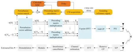
Figure 3. Overall system structure of nonlinear precoding in the downlink on TDD mode.
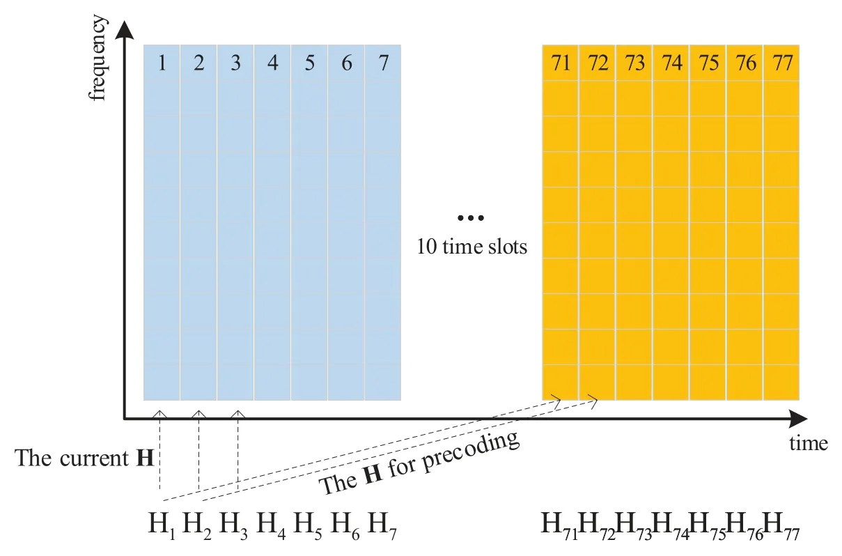
Figure 4. Block diagram of the time delay model.
After passing through the channelHt,i.e.,the current CSI,the received data at thek-th MS is represented as
The received data is then demodulated after the modulo operation as(15).
3.2 Proposed Robust NLP Scheme
The transmitter design of the proposed scheme is illustrated in Figure 5.The proposed scheme aims at mitigating the CSI error between the CSI used for precoding at the current time and the actual channel experienced by the data.The process is described in details as follows.
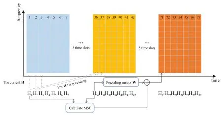
Figure 5. Transmitter structure of the proposed scheme with time delay.
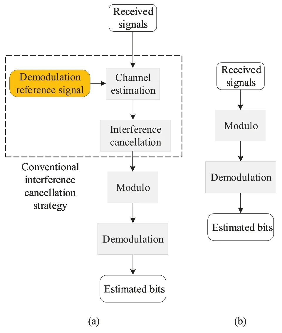
Figure 6. The receiver structure of nonlinear precoding:(a) conventional receiver process;(b) proposed simplified receiver process.
Step 1:Obtain the channel information,such as channel matrix,channel covariance matrix and interference covariance matrix,at time slotsN−t1andN−t2.Note that the value of the delay intervalt=t2−t1is determined by at least one of the parameters such as the number of BS antennas,precoding granularity and user mobile speed.
Step 2:According to the channel information of time slotsN−t1andN−t2,the MSE value of channel change in time delaytis calculated as
Step 3:According to the MSE value and the channel information at time slotN−t1,the channel information at time slotNis estimated.If the channel information is a channel matrix,then the precoding matrix at time slotNis calculated as
If it is a channel covariance matrix,then the channel information at time slotNis calculated as
Step 4:According to the channel information at time slotN,determine the precoding matrix.
Step 5:The signal is precoded according to the obtained precoding matrix.
Using the precoding matrix in(20),the transmit signals can be represented as
By utilizing the singular value decomposition(SVD),we can represent the power ofas
(23)can be rewritten as
As the vector norm remains invariant when multiplied by a unitary matrix,,i.e.,‖Vx‖2=‖x‖2,the expectation of(25)can be calculated as
whereE(·)is the expectation function.
As can be seen from(26),the power of transmit signals precoded byreduces compared to that precoded by,which results in smallerγ.Therefore,at the receiver,the noise has been amplified to a lesser degree.By utilizing MSE calculations for channels with adjacent delay intervals and adjusting the current precoding matrix accordingly,a more accurate precoding matrix can be constructed.This significantly enhances the performance of nonlinear precoding.Moreover,achieving optimal nonlinear precoding performance requires the optimization of the delay interval for various system configurations.This issue will be further discussed in Section VI.
IV.RECEIVER DESIGN FOR NONLINEAR PRECODING
In LP,the equalization is utilized to eliminate residual multi-user interference,which in turn incurs higher implementation costs at UEs.Meanwhile,the modulo operation in NLP may impact the equalization’s effectiveness in reducing interference.For alleviating this issue,in this section,we put forth the design of a receiver intended for nonlinear precoding.
4.1 System Model
We consider a MIMO system with precoding matrixW.The received signal can be represented as
In practical scenarios,the matrixHWcannot consistently be the identity matrixIdue to the imperfect CSI.Consequently,the residual multi-user interference becomes non-negligible,as the non-zero values of non-diagonal elements inHWintroduce additional interference.Typically,in LP,interference rejection combining (IRC) [23] equalization was suggested to achieve better performance.The detailed processing is summarized as follows.
The LP receiver first calculates the IRC equalization matrix as
whereGi=is the interference matrix of other users.Then the received signal is equalized byWIRCand the normalization factorβas
While IRC equalization offers improved performance,it substantially increases computational complexity and requires additional interference matrix information at the receiver.Simultaneously,the modulo operation in NLP may affect the equalization’s effectiveness in reducing interference.Due to inherent disparities in precoding architectures,the previously mentioned equalization method is unsuitable for NLP systems.Consequently,we introduce a more concise and effective receiver architecture tailored for NLP,as outlined below.
Step 1:Normalize the received signal byβas.
Step 2:Perform the modulo function on.
Step 3:Obtain the estimated bits by demodulating.
As a result,the receiver implementation is significantly simplified,requiring only a normalization factor and modulo operation,in contrast to LP.Importantly,simulation results will exhibit that the performance of the proposed receiver architecture outperforms its equalized counterpart.
4.2 Performance Analysis
In this section,we analyze both LP and NLP,exemplified by ZF and VP respectively,in the context of perfect and imperfect estimated CSI.This analysis aims to quantify the potential performance degradation resulting from equalization procedures.
4.2.1 Under Accurate CSI
For analytical convenience,we assume that the number of transmit antennas at the BS is equal to the number of receive antennas at the UE,i.e.,Nt=Nr.Note that this assumption is adopted for simplification and can be extended to more general settings.
1)ZF:For conventional ZF,the precoding matrix is the pseudo inverse of the channel matrix,expressed asW=H†.Then the transmit signals are represented asβWx,whereβis the power normalization factor and can be calculated as
If the CSI is accurate,we haveHW=I.At the receiver,the received signals can be simplified to
In this case,when the CSI is perfect,there is no residual multi-user interference.Consequently,the estimation of the transmit signals can be expressed as
Becauseβis typically less than 1,noise will be amplified at the receiver.Traditional IRC equalization can balance the noise and interference,ensuring that the norm of its precoding matrix is less than the ZF norm,so as to alleviate the impact of noise interference.
2)VP:For the nonlinear VP,a perturbation vector is added to the transmit signals toward the least transmit power.Here the transmit signals is represented asβW(x+τl),whileβis calculated as
Similarly,the accurate CSI rendersHW=I.The receiver can recover the transmit signals even without equalizer as
4.2.2 Under Inaccurate CSI
In practical situations,the CSI for precoding cannot be perfect due to channel delay,channel estimation error,precoding granularity greater than 1 subcarrier,and so on.As a result,the residual multi-user interference cannot be ignored.Therefore,we haveHWI,indicating that the non-zero values of non-diagonal elements inHWintroduce multi-user interference.Note that
In (35),the norm of diagonal elements is larger as it approaches 1,while the norm of non-diagonal elements is typically smaller,representing multi-user interference.
1) ZF:For ZF precoding,the received signals can be expressed asy=βHWx+n,whereHWI.Thek-th steam is then represented asyk=β[HW]kx+n,where[·]kdenotes thek-th row a matrix and[HW]k=[ak1ak2···].Then,ykcan be rewritten as
wherenkandxkrepresent the noise and transmit signal of thek-th stream,respectively.Letik=ak1x1+···+akNtxNtbe the interference,thenykcan be expressed as
Thek-th signal can be recovered as
As can be seen from(38),the performance will suffer from the interferenceik.
LetG=(HW)†be the equalization matrix,where
Then the receiver signals after equalization can be represented as
LetGk=[G]k=[gk1gk2···gkk···gkNt]represent the equalization vector of thek-th stream.Then the equalizedykcan be expressed as
The recoveredk-th signal is then obtained as
2)VP:For VP,thek-th received signal is expressed as
wherelirepresents the perturbation of thei-th stream.Eq.(43)can be rewritten as
whereik=ak1x1+···+ak(k−1)xk+1+ak(k+1)xk+1+···+akNtxNtdenotes the multi-user interference.
LetAbeHW,then we arrive at
Since thepin(45)is no longer an integer when the CSI is inaccurate,the perturbation cannot be completely eliminated by the modulo operation.
Then,the estimatedk-th stream signal after modulo is given as
If the equalizer is not employed,both residual multiuser interference and residual perturbation interference will jointly affect the transmit signals.Meanwhile,the noise will not be amplified,and there will be no introduction of interference from other streams.
In this case,by adopting an equalizer to alleviate the interference,thek-th equalized signals can be expressed as
which can be detailed as
Then,the estimated signal is obtained by the modulo operation as(49).
Furthermore,(49)can be simplified to
whereikgis the interference after the equalization,and mod(τGkAl) is the residual modulo interference,which is calculated to be 0 due toGkA=[0···1···0].Therefore,the inference residue term can also be eliminated to zero completely.
By employing the IRC equalization,we haveikg=0 andgkkakk=1.Eq.(49) can be further expressed as
As can be seen from (51),an additional interference vectorGk=[gk1···gkk···gkNt]is introduced although the multi-user interference is eliminated.Generally,the norm ofGkis greater than 1,leading to the amplification of noise once more.
Table 1 presents an overview of the estimated signals through ZF and VP precoding methods.Our analysis indicates that in ZF precoding,the interferenceikis the primary factor for performance degradation in the presence of inaccurate CSI.Although equalization introduces a higher level of noise,the benefits of interference elimination outweigh the drawbacks of noise amplification.

Table 1. The estimated signals of ZF and VP precoding.
In contrast,within the VP technique,both multiuser interference and perturbation interference coalesce,potentially resulting in amplification or reduction of total interference.However,even without equalization at the receiver,noise remains unaffected.Additionally,through the imposition of a modulo operation,interference and noise are restricted within a limited range.Notably,the main diagonal elementsakkapproximate unity,exerting minimal impact on overall detection performance.Conversely,the application of equalization amplifies noise and introduces interference from other streams,leading to significant performance degradation.As inferred from the above,in NLP,the proposed receiver structure manifests superior performance with extremely simplified processing.
V.PRACTICAL IMPLEMENTATION
In this section,we implement the developed NLP schemes using the universal software radio peripheral(USRP) communication environment to validate the simulation results.Our testbed comprises four transmit antennas and four receive antennas.The system test processing includes both hardware and software components,as illustrated in Figure 7.The hardware setup involves a PC mainframe case,the PXI remote control device,as well as the USRP RIO software radio equipment.Software components manage data generation,correlation processing,and transmission at the transmitter,while data reception,processing,and recovery occur at the receiver,all implemented using LabVIEW.

Figure 7. The Basic flow chart of data bits from generation to recovery.
LabVIEW is utilized for generating data bitstreams,performing modulation,and facilitating transmission to the designated PC.The USRP RIO box transmits data symbols through the selected antenna based on predefined software parameters.These symbols pass through the spatial channel and return to the PC via the USRP RIO box.Subsequently,the transmitted data bitstream undergoes successful recovery through software-driven demodulation.
5.1 The Testbed Hardware
The setup includes two USRP RIO devices serving as the transmitter and receiver,both equipped with VERT 2450-type vertical omnidirectional antennas with a dual-band range(2.4 to 2.48 GHz and 4.9 to 5.9 GHz)with 3 dBi gain.The hardware configurations are as follows.
• PXIe-1082 mainframe;
• PXI remote control module;
• PXI Express module: NI-PXIe-8374;
• USRP RIO software radio device: NI-USRP-2942.
For data transmission,the PXIe-1082 mainframe connects to the PXI Express module NI-PXIe-8374 at both ends.A PXI remote control module facilitates the hardware connection for data transmission.The NI-USRP-2942 device,used for MIMO transmission,covers a carrier frequency range of 400 MHz to 4.4 GHz with a 40 MHz RF bandwidth.It offers transmit output power of up to 20 dBm and receive output power ranging up to-15 dBm.This device is equipped with a programmable (Xilinx Kintex-7) FPGA and two 40 MHz bandwidth RF transceivers.The layout of the USRP RIO equipment is shown in Figure 8,and specific hardware parameters for the NI-USRP-2942 device are provided in Table 2 and Table 3.
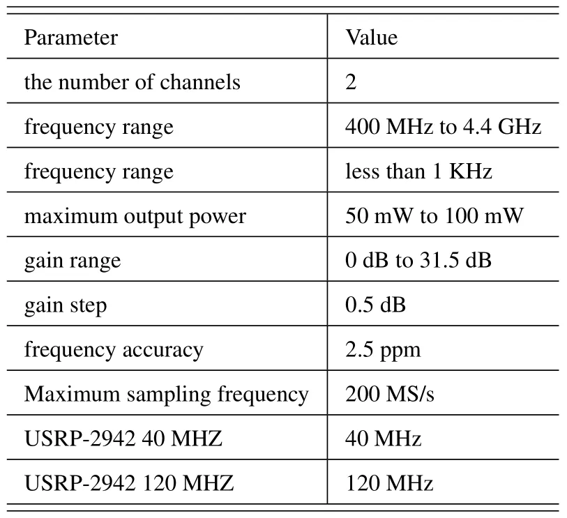
Table 2. The transmitter parameters of NI-USRP-2942 device.
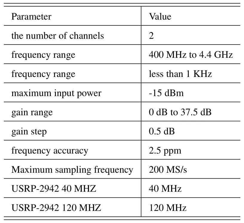
Table 3. The receiver parameters of NI-USRP-2942 device.
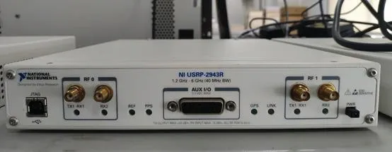
Figure 8. The NI-USRP-2943 equipment.
5.2 The Testbed Software
To enable the generation and reception of mainframe data at both the transmitter and receiver ends,we leverage LabVIEW programming for activating the corresponding USRP RIO device.A visual representation of the specific implementation process is presented in Figure 9.
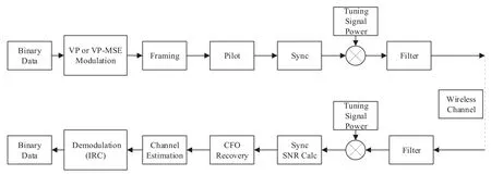
Figure 9. Implementation flow of USRP platform.
5.2.1 Processes from Original Bits to Transmission Data
At the transmitter,binary data is firstly generated and processed.Subsequently,these data are transmitted from the transmit antennas and propagated through the space environment to reach the receive antennas.
a)Frame Structure Design
After data generation,the binary data is processed and converted into symbol data frames.Each frame consists of 14 OFDM symbols with an FFT length of 1024,including 4 synchronous symbols,4 data symbols,2 pilot symbols,and 4 training symbols.The frame structure is depicted in Figure 10.

Figure 10. The frame structure design.
b)Modulation Process
The transmitter data frame is modulated using either conventional VP or the proposed VP-MSE schemes.
1.Conventional VP: As both the transmit and receive data processing takes place on the same PC,the CSI can be easily achieved.Feedback data is stored in variables within the software for ease of programming.The steps used to generate VP modulation symbols are summarized as follows.
Step 1:Binary bit stream is mapped through constellation to generate constellation symbol.QPSK modulation is adopted in the system.
Step 2:Based on ZF criterion,the average value ofHfor every four subcarriers is calculated to construct precoding matrix as
Step 3:Search for the optimal perturbation vector as
Step 4:Add the perturbation vector to obtain transmission symbols as
2.Proposed VP:The proposed VP scheme compensates for delay caused errors in the channel by computing the MSE of two channels with simultaneous delay intervals.Specifically,for the current time slot,the actual channel is denoted asHi,while the average value ofHused for precoding,obtained from the previous delay,is represented as.For the last time slot,the actual channel experienced isHi−1,and the average value of the channel used in the precoding matrix is represented asHi−2.The MSE is then calculated as
Then the MSE value is compensated to obtain the precoding matrix of the current time as
The remaining steps of the proposed VP modulation processing are identical to those of the conventional VP scheme.To simplify the transmitter and minimize system interruption,the receiver calculates the precoding matrix and sends it as feedback data,instead of the traditional approach of transmitting channel estimations.
c)Parameter storage
To assure accurate demodulation of the receiver’s data and achieve effective IRC equalization using the precoding matrixW,the system stores bothandW.
d)Pilot Placement and Addition of CP
The pilot sequence is placed utilizing two OFDM symbols while adopting the time-division block pilot mapping method,as depicted in Figure 11.The experiment employs the Zadoff-Chu(ZC)pilot sequence.
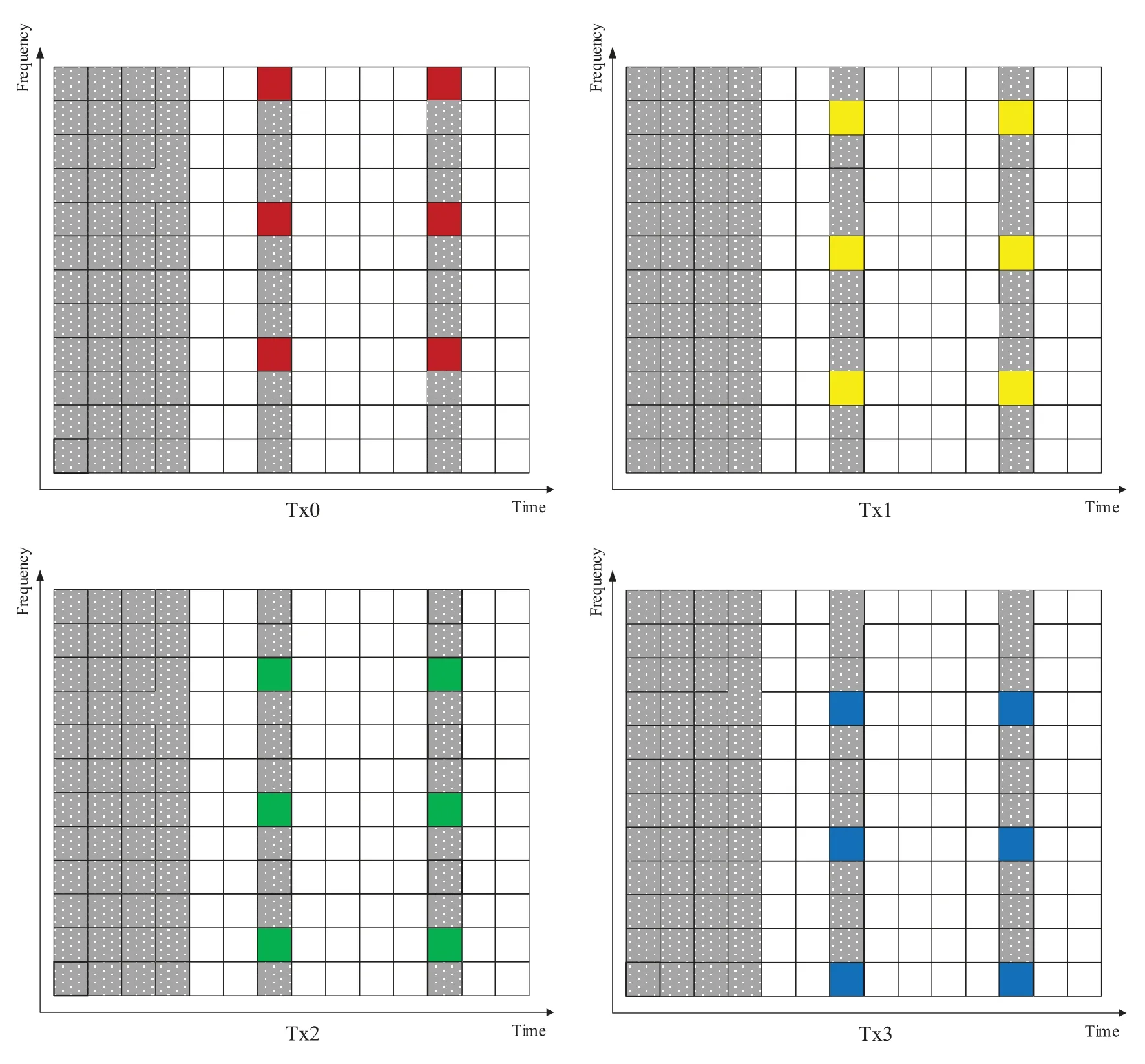
Figure 11. The pilot placement of the practical implementation.
e) Synchronization Sequence Insertion at the Transmitter
Each frame contains four symbol data.The first two symbol positions are reserved for frame synchronization data,while the last two symbol positions contain “0” and “1” crossed data used for SNR estimation at the receiver.The ZC sequence is employed for training,with frame synchronization data inserted in two consecutive training symbols.This facilitates carrier frequency offset(CFO)estimation at the receiver,along with data synchronization.
f)Signal Power Variation
The signal power fluctuations result in varying SNRs,which can be estimated by manipulating the output signal amplitude and setting the output signal power parameters accordingly.
g)Upsampling and Filtering
To combat ICI and ISI and ensure signal stability,a square-root raised cosine roll-off filter is applied.This specific filter is chosen from the LabVIEW modulation toolkit and involves sixteen times oversampling per frame.After implementing these signal processing methods,the data is transmitted using the PXIe broadcasting system.
5.2.2 Processes from Received Data to Estimated Bits
At the receiver,the data is firstly captured by the PXIe and subsequently processed through the Lab-VIEW programming software for binary data restoration.Achieving this requires the implementation of the following steps.
a)Downsampling and Filtering
Upon reception,the data is processed using a data capturing module.It then passes through a square-root raised cosine roll-off filter,with each data frame being down-sampled by a factor of sixteen.
b)Synchronization at the Receiver
Two ZC sequences with equal length are incorporated into the synchronization sequence,to facilitate synchronization of both timing and frequency.
c)The SNR Calculation
Within each frame,the third and fourth symbols are alternately set to be 0 and 1 as data,enabling the computation of the received SNR as
d)Valid Data Frame Storage
Once the data is received,it undergoes synchronization processing,and any redundancy is subsequently eliminated.The data is then stored in a queue,frame by frame,to safeguard against the data acquisition module crashing due to processing time delays.
e)Channel Estimation
In this experiment,the channel information is estimated by the least square (LS) algorithm and linear interpolation.
f)Channel Information Feedback
After channel estimation,we compute the precoding matrix for the upcoming frame’s data.We store this matrix using variables,enabling the feedback of channel information.
g)Data Demodulation
The demodulation process is as follows.
1.Duplicate copies of the received data are created,with one copy subjected to proposed receiving algorithm processing,while the other undergoes IRC equalization.The subsequent operations are the same.
2.Firstly eliminate the normalization factor,and then carry out the modulo operation as
3.Obtain the demodulated bit data by demapping constellation symbols.
4.Compare the demodulated data with the data original at the transmitter,so as to quantify the the BER performance.
Finally,the BERs can be obtained by the recovered data bits.
5.3 Environment of Signal Transmission
Figure 12 portrays the actual environment in which the signal transmission is carried out,where Tx and Rx represent the transmit and receive antennas,respectively.The transmit and the receive antennas utilized in the experiment are identical.During the placement process,both the transmitter and the receiver are positioned directly opposite to each other,with no obstruction present in the middle of the channel.This configuration results in a channel model referred to as line of sight (LOS).The carrier frequency employed in the transmission process is 2.5 GHz.
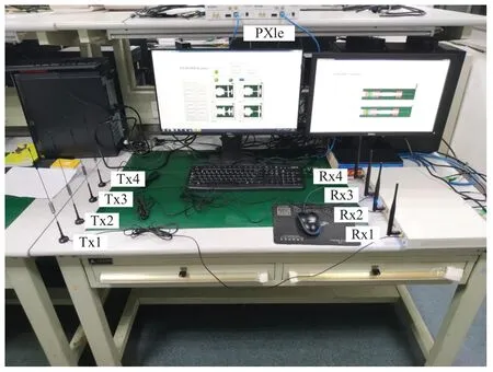
Figure 12. Experimental setup in the laboratory.
VI.PERFORMANCE EVALUATION
In this section,we present the performance evaluation of the developed transceiver structure for NLP under various antenna configurations.The system performance assessment is conducted via Monte Carlo simulations,while the total transmit power holds constant for all schemes.In addition,we adopt LTE parameters to reflect the suitability of our schemes for 6G.The mobile speed is set as 3 km/h,while the precoding interval is based on one RB incorporating 12 subcarriers.Moreover,we implement the TDL-B channel specified in the 5G standard protocol,featuring a time delay of 5 ms.
6.1 Computer Simulations
In Figure 13,we compare the performance of the robust transmitter design with different OFDM symbolbased compensation intervals (OSCI) for the VP precoding design.The BS is equipped withNt=4 transmit antennas,while there areNu=4 users,each with a single receive antenna.Notably,the original VP demonstrates inferior performance compared to ZF under practical communication environments.Conversely,our proposed robust scheme offers significant improvements over regular VP precoding by mitigating the channel estimation error caused by time delay.Additionally,the performance gain from our proposed scheme is dependent on the selection of MSE calculation intervals.Our simulations suggest that 25 OSCIs provide optimal results for compensating time delay errors.
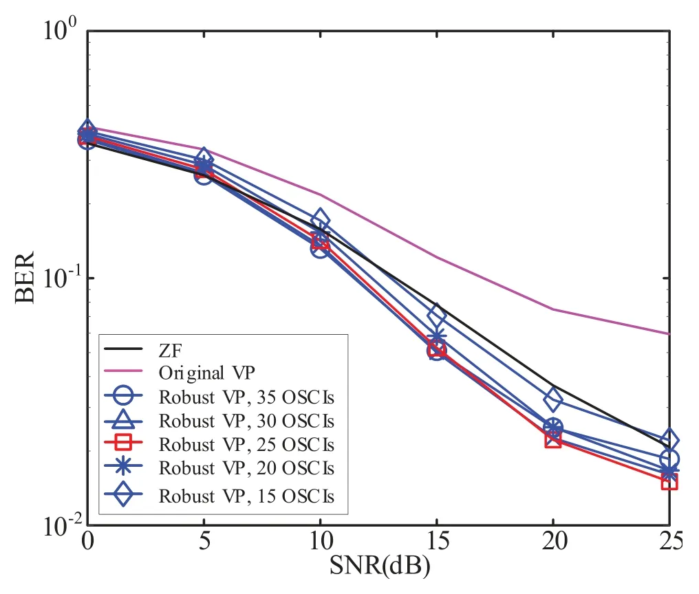
Figure 13. Performance of the proposed system with various compensation intervals when Nt=4,Nu=4 and Nr=1.
In Figure 14,we present the BER performance of the proposed transmitter implemented under various system configurations.During the simulation,a BS equipped withNt=8 transmit antennas andNu=4 users,each possessingNr=2 receive antennas,were considered.Our designed robust transmitter significantly improves BER performance through the attainment of an accurate precoding matrix.Notably,the simulation results reveal that 20 OSCIs provide optimal performance in this scenario.
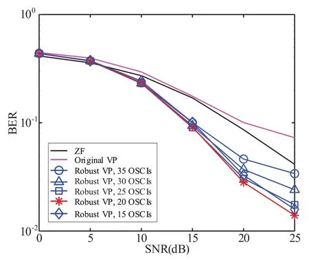
Figure 14. Performance of the proposed system with various compensation intervals when Nt=8,Nu=4 and Nr=2.
In Figure 15,we compare the BER performance of both ZF and VP precoding schemes with the simplified receiver.The simulation considers a BS equipped withNt=8 transmit antennas andNu=8 users,each with a single receive antenna.Two and four RB precoding intervals are adopted.As shown in Figure 15,the conventional receiver with IRC equalization provides better performance for ZF precoding by eliminating the multiuser interference.However,for VP precoding,the proposed simplified receiver,i.e.,without IRC equalization,exhibits better performance.The conventional receiver,conversely,worsens the BER performance.This interesting result reveals that the equalizer introduces extra interference due to the modulo operation,as analysed in Section III.This observation is critical to the NLP application,where the modulo operation is widely utilized.
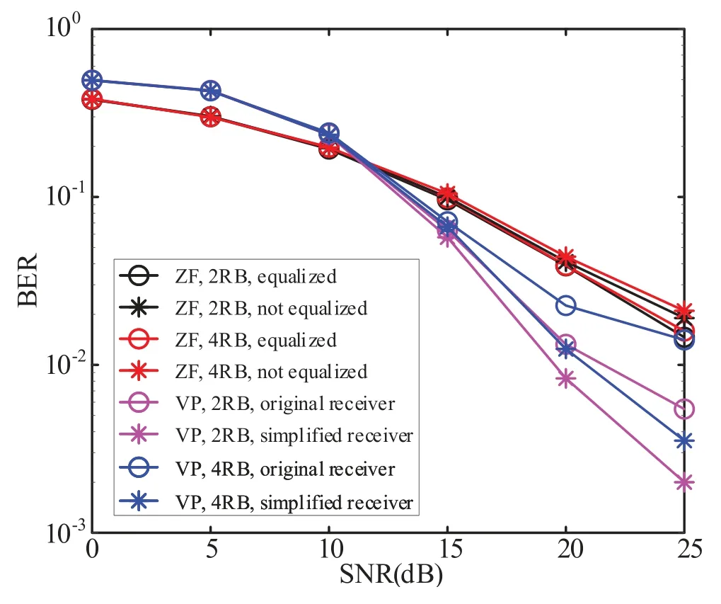
Figure 15. Performance comparison between ZF and VP systems with the proposed receiver when Nt=8,Nu=8 and Nr=1.
In Figure 16,we compare the BER performance of ZF and VP precoding schemes under perfect and imperfect CSI.As shown in Figure 16,the original VP provides an even worse performance than ZF,making it difficult to implement in practical scenarios.However,the proposed VP structure significantly improves performance and demonstrates that the developed NLP scheme is more robust to imperfect CSI,resulting in better performance in practical systems.Meanwhile,in Figure 17,we compare the BER performance of ZF and THP precoding schemes under perfect and imperfect CSI.Figure 17 illustrates that our proposed scheme can deliver better BER performance under imperfect CSI when compared to the original THP.Additionally,we compare the BER performance between the multi-branch THP (MB-THP)scheme [19] and the rate-splitting multi-branch THP(RS-MB-THP) scheme [21].The results show that the proposed schemes can yield similar gains to RSMB-THP.Based on the performance evaluation in Figure 13-17,our proposed NLP transceiver structure can simplify receive processing and achieve considerable performance gains under practical channel estimation errors,compared to traditional LP counterparts.Therefore,NLP has the potential to play a significant role in the physical layer of upcoming 6G networks.
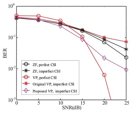
Figure 16. Performance comparison between ZF and VP systems with the proposed schemes under perfect and imperfect CSI when Nt=8,Nu=4 and Nr=2.
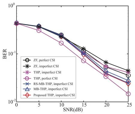
Figure 17. Performance comparison between ZF and THP systems with the proposed schemes under perfect and imperfect CSI when Nt=4,Nu=4 and Nr=1.
6.2 Practical Experiments
The experimental result for the proposed transceiver structure is shown in Figure 18.The experiment is conducted with four transmit antennas and four receive antennas,and the system parameters are detailed in Section V.In this experiment,the channel is a LOS channel.Due to the receiver-end calculation of the precoding matrix,there is a significant time delay in the test.As demonstrated in Figure 18,VP precoding with the proposed error compensation processing achieves a 3 dB performance gain at a BER of 10−2over the conventional scheme.Furthermore,the proposed simplified receiver improves the performance by approximately 1 dB.Therefore,the experimental results validate our computer simulation results.
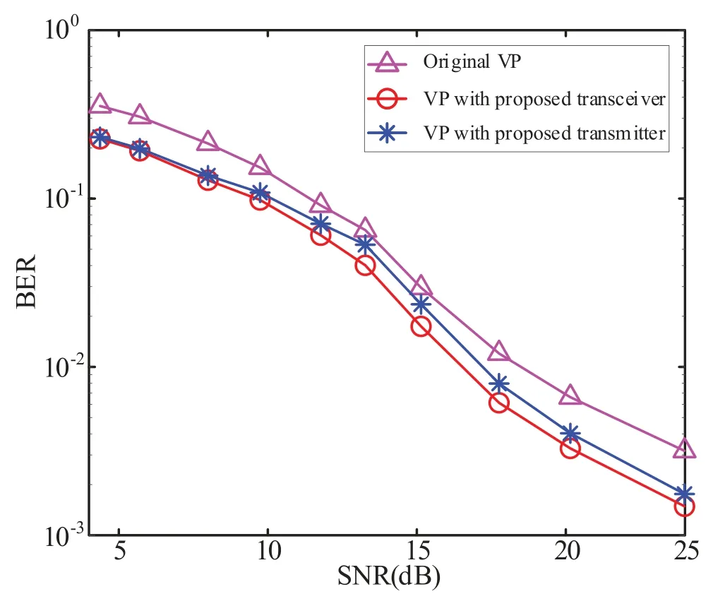
Figure 18. Practical performance comparison among ZF and VP systems of the proposed transceiver when Nt=4,Nu=4 and Nr=1.
VII.CONCLUSION
In this paper,we conceived a robust NLP design along with a simplified receiver designed for MIMO-SDMA systems,in the context of imperfect channels.We demonstrated that the designed NLP structure is robust to imperfect CSI,which as been ever considered as a key limitation of NLP.Furthermore,the extremely simplified receiver structure,even free of equalization,will facilitate the downlink transmission especially for internet of things(IoT).Finally,by computer simulations and experimental testbed,we exhibit that NLP has the potential to be a promising transmission techniques for future 6G communications.
ACKNOWLEDGEMENT
This work is supported in part by National Key R&D Program of China (2020YFB1807203),National Science Foundation of China under Grant number 62071111,the Fundamental Research Funds for the Central Universities under Grant 2242022k60006,Natural Science Foundation of Sichuan Province under Grant number 2022NSFSC0487 and the National Key Laboratory of Wireless Communications Foundation under Grant IFN20230104.
- China Communications的其它文章
- Design Framework of Unsourced Multiple Access for 6G Massive IoT
- 6G New Multiple Access Technology
- OFDMA-Based Unsourced Random Access in LEO Satellite Internet of Things
- Cluster-Based Massive Access for Massive MIMO Systems
- A Joint Activity and Data Detection Scheme for Asynchronous Grant-Free Rateless Multiple Access
- The Extended Hybrid Carrier-Based Multiple Access Technology for High Mobility Scenarios

