Prediction of atomization characteristics of pressure swirl nozzle with different structures
Jinfan Liu, Xin Feng, Hu Liang, Weipeng Zhang, Yuanyuan Hui Haohan Xu Chao Yang,3
1 School of Chemical Engineering, Sichuan University, Chengdu 610065, China
2 CAS Key Laboratory of Green Process and Engineering, Institute of Process Engineering, Chinese Academy of Sciences, Beijing 100190, China
3 School of Chemical Engineering, University of Chinese Academy of Sciences, Beijing 100049, China
4 College of Chemical Engineering, Nanjing Tech University, Nanjing 211816, China
Keywords: Pressure swirl nozzle Nozzle structure Numerical simulation Spray angle Prediction
ABSTRACT The structure of the pressure swirl nozzle is an important factor affecting its spray performance. This work aims to study pressure swirl nozzles with different structures by experiment and simulation. In the experiment,10 nozzles with different structures are designed to comprehensively cover various geometric factors. In terms of simulation, steady-state simulation with less computational complexity is used to study the flow inside the nozzle. The results show that the diameter of the inlet and outlet,the direction of the inlet,the diameter of the swirl chamber,and the height of the swirl chamber all affect the atomization performance, and the diameter of the inlet and outlet has a greater impact. It is found that under the same flow rate and pressure, the geometric differences do have a significant impact on the atomization characteristics, such as spray angle and SMD (Sauter mean diameter). Specific nozzle structures can be customized according to the actual needs. Data analysis shows that the spray angle is related to the swirl number, and the SMD is related to turbulent kinetic energy. Through data fitting,the equations for predicting the spray angle and the SMD are obtained.The error range of the fitting equation for the prediction of spray angle and SMD is within 15% and 10% respectively. The prediction is expected to be used in engineering to estimate the spray performance at the beginning of a real project.
1. Introduction
Pressure swirl nozzles have been widely used for decades in industrial burners[1],cooling[2],agricultural[3],and other applications [4,5]. Pressure swirl nozzles are easy to manufacture even at the small sizes, have good atomization quality, and have a low tendency in clogging. The simplest type of pressure swirl nozzle is the simplex nozzle. Liquid at high pressure is supplied to the nozzle through purely tangential ports and finally discharged from an outlet orifice[6].The liquid is first turned into a liquid film and finally atomized into droplets. Although the structure of the pressure swirl nozzle is simple, the internal flow is perhaps extremely complex. Understanding the internal flow in a pressure swirl nozzle and the key factors affecting its properties are of great importance for producing high-quality atomized droplets.
Earlier theoretical studies on swirl nozzles focused on inviscid analysis. However, the non-viscous hypothesis would lead to a large deviation in predicting the spray angle and discharge coefficient of the nozzle at a small scale[7].Through theoretical analysis and experimental verification, Amini [8] revealed the influence of viscosity and axial velocity on the liquid film thickness, atomization spray angle,and discharge coefficient,providing better criteria for the design and analysis of nozzles.
Pressure swirl nozzles have been studied experimentally by many researchers. Some researchers observed the internal flow phenomenon by preparing a transparent nozzle and found that there was a stable air core inside the pressure swirl nozzle[6,9,10]. The shape of the air core has an important influence on the flow field inside the nozzle. It was observed that the air core in the nozzle was stable, and cylindrical with a slight expansion near the outlet [6]. A larger air core diameter means a thinner liquid film thickness at the nozzle outlet,which affects the size of atomized droplets.
With the development of measurement technology,new methods are used in the research of nozzles. High-speed imaging has been widely used to measure film thickness and jetting angle[11–13]. The droplet size and velocity distribution have been measured by phase doppler particle analyzer(PDPA).Sauter mean diameter (SMD),D32, the droplet size in statistical sense, has been widely used for an objective evaluation of atomization. Maoet al.[14] used a laser particle size testing system to test the SMD of spray. Then, combining temperature, pressure, injection distance,and nozzle structural parameters, an SMD prediction model was established.Yaoet al.[15]used PDPA to measure the spatial distribution of spray droplet size. The results showed that it decreased with the distance from the nozzle outlet, and the SMD at the central axis was larger than that in the periphery.Wanget al.[16]used PDPA to analyze droplet size and velocity, showing that as the spray distance increased, the droplet velocity decreased significantly and the SMD decreased. Yuet al. [17] studied the influence of spray height,flow rate and temperature on the average diameter of atomized droplets through a laser measurement system.
To further understand the two-phase flow behavior of pressure swirl nozzles, numerical simulation methods are widely used to provide flow details inside and outside the nozzle[18,19]and their relation to instability,breakup and atomization of the liquid sheet.Wanget al.[20] studied the internal flow characteristics of the pressure swirl nozzle and the breakup of the liquid film outside the nozzle by computational fluid dynamics. Belhadefet al.[21]developed an Eulerian model to model liquid sheet atomization with high Weber and Reynolds numbers. Chenet al.[22] found through LES(large eddy simulation)–VOF(volume of fluid)simulation of pressure swirl nozzle that the formation of air core was mainly due to centrifugal force overcoming viscous force, so viscosity may have an important effect on nozzle performance.Gicquelet al.[23] used the VOF–DPM (discrete phase model)method to model multiphase flow to reduce the computational cost to a large extent by allowing the small droplets to be tracked in larger cells using the Lagrangian method.Using deep learning,Liet al.[13] explored the relationship between image analysis metrics and the size of the generated atomized droplets,and achieved the goal of estimating the droplet size based on image features.
However,in the nozzle simulations,most of them use the transient method, resulting in a long running time. For most simulations of the spray, the existing empirical equations are used,which are not accurate and have a narrow scope of application,and it is impossible to study the influence of various nozzle structures on atomization properties. The VOF to DPM method has emerged in recent years, which requires a finer mesh to capture the details of the first atomization process. At the same time, the spray area is large, so a huge number of grids is required, which greatly increases the load of calculation.
The nozzle assumes a critical role in atomization and its geometric parameters determine the atomization performance to a large extent [24]. The structure of the pressure swirl nozzle has been studied by many researchers [25,26]. Xueet al. [27] studied experimentally the effect of four geometric parameters on the performance of the atomizer, namely, inlet slot angle, spin chamber convergence angle, trumpet angle, and trumpet length. Results indicated that an increase in inlet slot angle resulted in lower film thickness and discharge coefficient and higher spray cone angle.The spin chamber converges angle had the opposite effect on performance parameters. Amini [8] found that the spray angle, discharge coefficient, and air core radius were inverse functions of the nozzle length. Among the multiple geometric parameters of the nozzle, the effect of the orifice diameter is more prominent,because the inertia of the liquid inside and outside the nozzle is very large, which is controlled by the hole area [28]. Based on the orthogonal experiment method,Liet al.[29]studied the interaction between the SMD of the nozzle and the three influencing factors of air pressure, water pressure and outlet diameter. However, in previous studies, the geometrical factors of pressure swirl nozzles have not been comprehensively studied.At the same time,the atomization performance of nozzles with different structures cannot be directly judged. It is necessary to study a low-cost simulation method to predict the atomization effect.
In this paper, the method of combining simulation and experiment is used to study the influence of nozzle structure on atomization characteristics. In the experiment, 10 nozzles with different structures were customized. Experimental research was carried out by laser particle size test and photograph. Then the influence of the structure on the atomization characteristics such as flow rate, spray angle and SMD was analyzed by experimental results.The internal flow field of the nozzle was simulated by the steady-state simulation method.This will consume fewer computing resources.The flow field characteristics inside the nozzle were analyzed by simulation results.Finally,the internal flow data simulated were used to predict the external atomization performance.The fitting correlation was expected to be used to optimize the swirl nozzle structure according to the atomization requirements.
2. Experimental Methods
2.1. Experiment preparation
The control variable method was used for structural design, in which nozzle 1 was a standard structure. The specific size parameters of nozzle 1 are shown in Fig. 1.
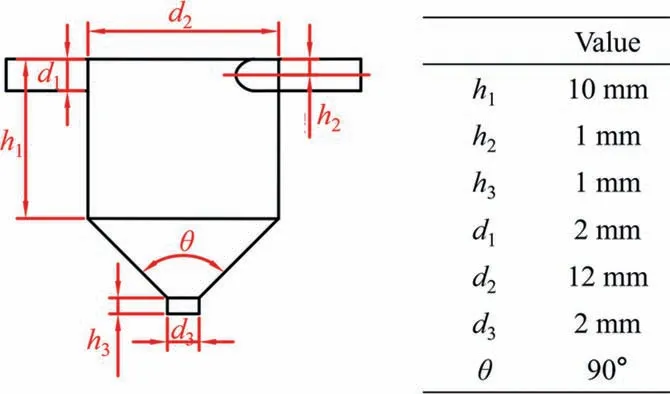
Fig. 1. Standard nozzle structure size parameters.
Ten nozzles with different internal structures were customized,and transparent acrylic material was selected as the nozzle material. These nozzles are numbered 1–10, and No. 2–10 nozzles are variations based on nozzle 1. The shapes of the internal zone of No. 1–10 nozzles are shown in Fig. 2. For convenience, No. 1–10 nozzles are all double-inlet nozzles. The specific change values of No. 2–9 nozzles are shown in Table 1.
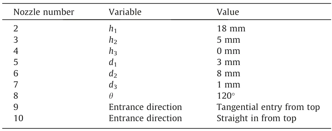
Table 1Nozzle structure comparison table
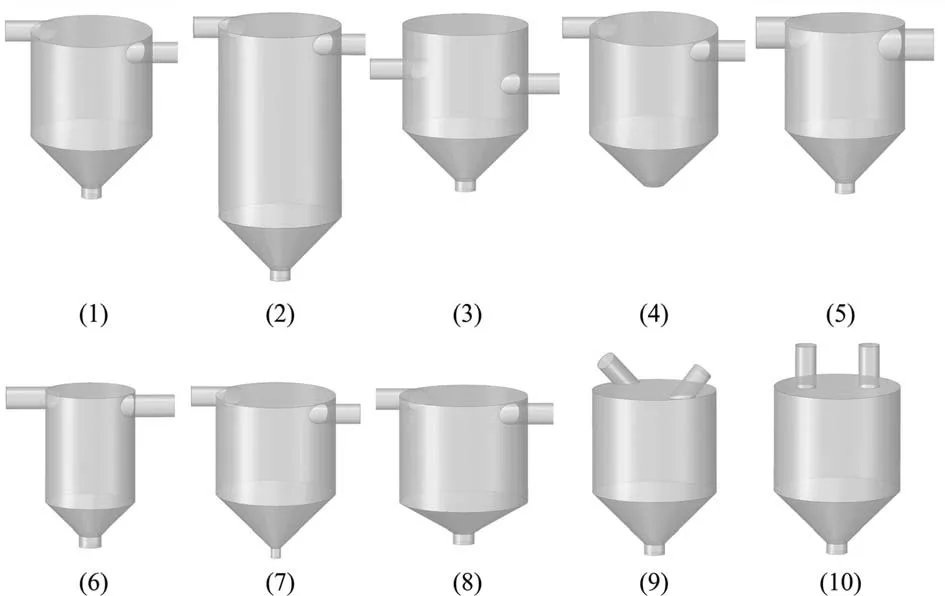
Fig. 2. Model diagrams of the nozzle with 10 structures.
Deionized water was chosen as the liquid phase and air as the gas phase. Experiments were performed at a room temperature of 25 °C.
2.2. Laser test method
As shown in Fig. 3(a), a laser particle size testing system is established, which consists of a spray system, a laser testing system,and a photographing system.Under different pressure conditions, 10 nozzles were tested for particle size, and the spray morphology was photographed. The spray system contains a flow monitoring device, which can measure the spray flow. The laser test system can measure the size distribution in the range of 0–2000 μm.At the same time,the laser test system comes with a lifting system, which can adjust the height distance from the measurement point to the nozzle outlet. The pressure range of the experiment is 100–400 kPa, at an interval of 50 kPa. After preexperiment, 200 mm directly below the nozzle was chosen as the test point. When the distance is shortened, the liquid phase is not completely atomized,and the droplet size exceeds the measuring range.Limited by the distance between the laser transmitter and the receiver, increasing the distance will cause droplets to splash on the receiver lens, which will interfere with the experimental results.
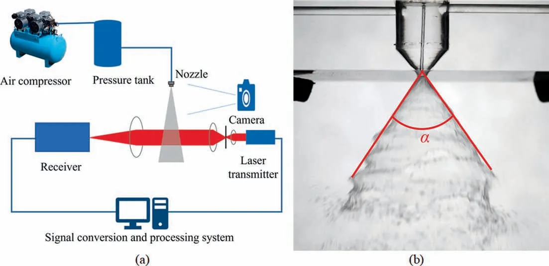
Fig. 3. (a) Schematic diagram of equipment. (b) Schematic diagram of spray angle measurement.
The spray topography can be obtained by photographing. The spray angle was measured using the ImageJ software according to the method shown in Fig. 3(b), and the average value was obtained from multiple measurements.
3. Computational Fluid Dynamics
3.1. Mathematical model
Computational fluid dynamics (CFD) simulation is an effective tool for predicting the flow field inside the nozzle and optimizing the nozzle structure.Firstly,a geometric model of the internal flow field of the nozzle was constructed. ANSYS fluent 2021 was used for the simulations. Steady-state calculations were performed for the selected internal flow field, and the renormalization group(RNG)k–ε turbulence model [30] and the two-phase VOF model[31] were selected. The RNG model is an improved form of thek–ε model. At high Reynolds numbers,the RNGk–ε model has the same form as the standardk–ε model,and an additional generation term is added to the equation to represent the flow rate when the flow is rapidly distorted.
The fluid ejection process in the nozzle is a gas–liquid twophase flow. To accurately describe the liquid film and droplets of the ejected fluid, a gas–liquid interface capture method needs to be established. The basic idea of the VOF model is to use a scalar function, namely volume fraction, to represent the distribution of fluid in the grid, and its size represents the percentage in the grid.The VOF model equation is as follows:
Momentum equation:
wheremqpis the mass transfer from phase q to phase p andmpqis the mass transfer from phase to phase.is zero, and is a userdefinable mass source.
3.2. Geometric model
To study the influence of the internal structure of the nozzle on the atomization effect, nozzle 1 was used as a standard case to study its internal flow field characteristics under different pressures. To better describe the position inside the nozzle, the origin of the coordinates is defined as the ‘‘O” point in Fig. 4(a), and the positive directions of the axial and radial directions are given.
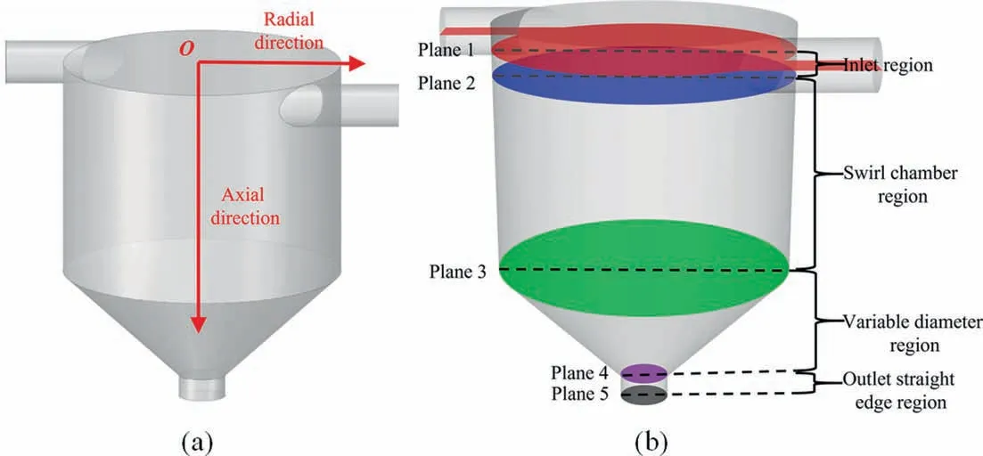
Fig. 4. (a) Coordinate system of the nozzle. (b) Dividing the inner region of the nozzle.
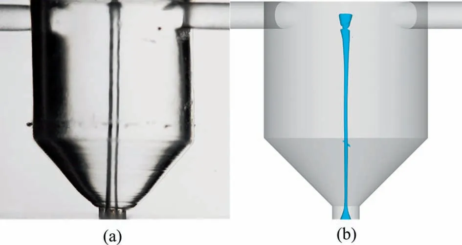
Fig. 5. Comparison of CFD simulation and experiment results: (a) experimental result, (b) simulated gas–liquid interface.
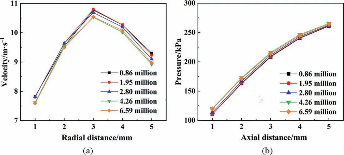
Fig. 6. Velocity distributions with different mesh numbers: (a) radial, (b) axial.
The geometric structures of the 10 nozzles are different, and various flow field data at different axial distances cannot be directly compared. Therefore, as shown in Fig. 4(b), five feature planes of the internal structure are selected to divide the nozzle into four study regions. The five feature planes are: plane 1 is the entrance center plane, plane 2 is the bottom end plane of the entrance,plane 3 is the plane where the diameter begins to change,plane 4 is the plane where the diameter ends changing,and plane 5 is the exit plane. The nozzle is divided into 4 research regions,namely the inlet region, swirl chamber, variable diameter region,and outlet straight edge region.
3.3. Model validation
To verify the accuracy of the model,the gas–liquid interface diagram of nozzle 1 at 300 kPa was simulated.Fig.5 shows that the air core appears in the simulation results.It is proved that the steadystate simulation of the internal flow field has a certain accuracy.However,the size of the air core cannot be completely corresponding,and the model does have some errors.In order to better verify the model. The nozzle with an external domain is simulated. The simulation conditions and meshing are the same as those in this paper. The experimental results have good validation for the simulation results. Details are in the Supplementary Material.
Meshing the computational domain was performed with different sizes by Workbench Meshing, and the flow field distribution was obtained by calculation. The air column has a great influence on the spray state, so the grid in the center area of the nozzle where the air column is located is smaller.As shown in Fig.6,when the grid number is 4.26 million,continuing to increase the number of grids,the flow field data is basically unchanged.The aspect ratio and Jacobian ratio of the grid are within a reasonable range to meet the computing needs. At the same time, this size can stably simulate the gas column phenomenon. Therefore, it is determined as the mesh size selected in this paper. The minimum size of the non-encrypted area is set to 0.15 mm, and the minimum size of the encrypted area is 0.05 mm. The grid diagram of nozzle 1 is shown in Fig. 7. The grids of the other 9 structures were drawn according to this size for simulation.
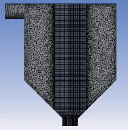
Fig. 7. Grid diagram of nozzle 1.
4. Results and Discussion
4.1. Atomization experiment
The atomization experiment tested the acrylic nozzles with 10 different structures. Nozzle 1 was defined as a standard nozzle.Considering the influence of working conditions on the atomization effect, a pressure of 100 kPa to 400 kPa at inlet was applied to all nozzles to explore the regular atomization pattern. In the experiment, photographing and laser testing were used to get the data on spray angle, and atomization particle size.
4.1.1. Discharge coefficient
As shown in Fig. 8(a), with the same pressure conditions, the internal structure of nozzle has a significant effect on the nozzle flow rate. The experimental results show that the flow rate of nozzle 5 is higher than that of the nozzle 1, and the flow rate of nozzle 7 is lower than that of nozzle 1.Analyzing the structural differences,the diameter of the inlet of nozzle 5 is larger than that of nozzle 1,and the diameter of the outlet of nozzle 7 is smaller than that of nozzle 1. Therefore, changing the diameter of the inlet and outlet can effectively adjust the flow rate. The inlet and outlet diameters affect the flow resistance in the nozzle, and increasing the diameter can reduce the flow resistance, thereby increasing the nozzle flow rate. The results are consistent with the effects of inlet and outlet on flow described by Rizk and Lefebvre [32].
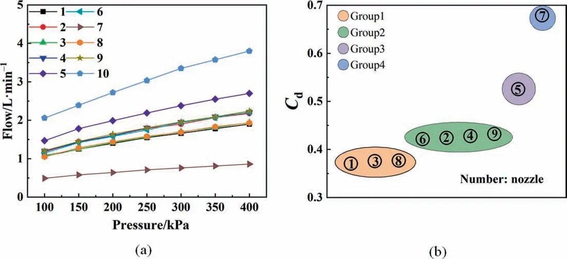
Fig. 8. Flow parameters of different nozzles: (a) flow rate, (b) discharge coefficient.

Fig. 9. Spray pictures of nozzle 1 with different pressures: (a) 100 kPa, (b) 200 kPa, (c) 300 kPa, (d) 400 kPa.
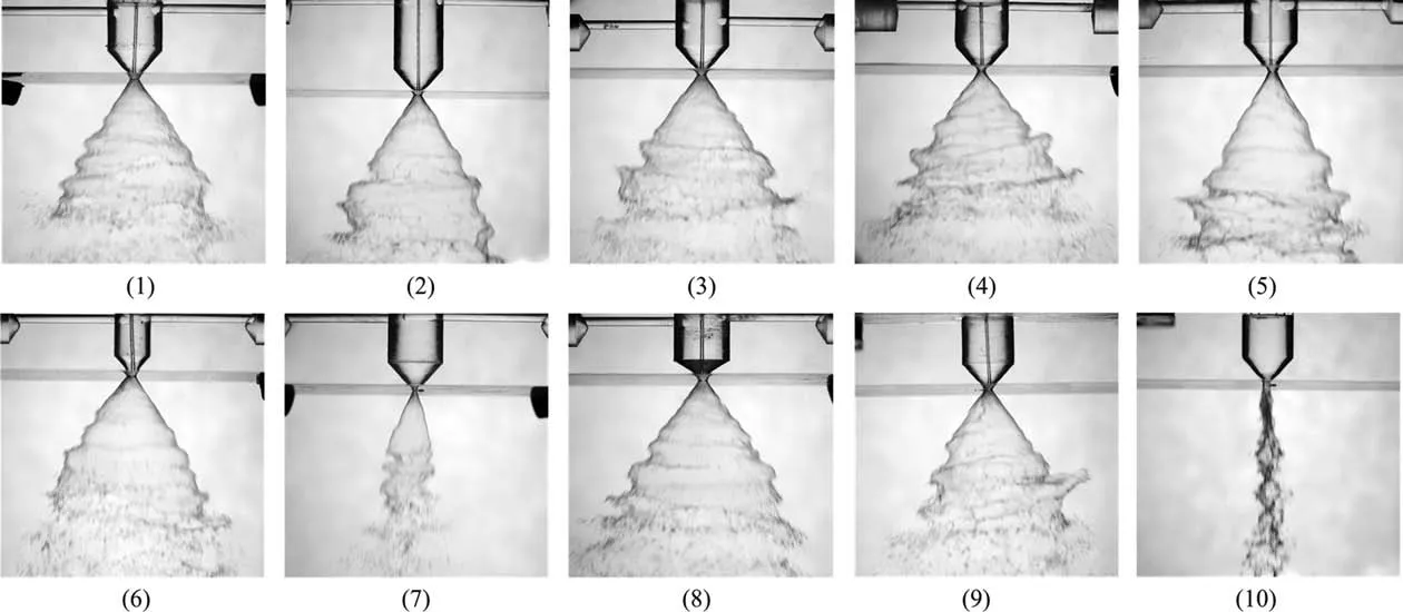
Fig. 10. Spray photos of different nozzles with a pressure of 100 kPa.
The flow rate of nozzle 3 and nozzle 8 is the same as that of nozzle 1 within the allowable range of error. Nozzle 3 moves the nozzle inlet position from the top of the swirl chamber to the middle part,which has no great influence on the flow.This phenomenon shows that only changing the inlet position has little influence on the flow.The angle of the reducer of nozzle 1 is 90°,and the angle of the variable diameter region of nozzle 8 is modified to 120°.There is no significant change in the flow rate, indicating that the angle at the variable diameter region has little effect on the flow rate.
The flow rate of nozzles 2,4,6,and 9 are all slightly larger than that of nozzle 1.These four kinds of nozzles show a strange consistency in the relationship between pressure and flow,which is worthy of in-depth analysis.Nozzle 2 increases the length of the swirl chamber. Nozzle 6 reduces the swirl chamber diameter. Looking for the same points of the two nozzles, it is found that, compared with nozzle 1, the length-to-diameter ratio of the swirl chamber is increased for both nozzle 2 and nozzle 6.It shows that increasing that ratio can increase the nozzle flow rate.Removing the straight edge of the outlet of nozzle 4, the flow resistance of the nozzle is reduced,thereby increasing the flow rate of the nozzle.The nozzle 9 changes the position of the inlet.At the same time,the horizontal tangential inlet was replaced with inclined downward inlet. This change increases the axial velocity component of the flow. An increase in the axial velocity component will increase.
Nozzle 10 has a greater flow rate than the other nozzles.Nozzle 10 does not use a tangential inlet and its internal flow is not characterized by swirl. Besides, nozzle 10 has a poor atomization performance, so nozzle 10 will not be discussed.
The discharge coefficientCdis an extremely important parameter with regard to the design of atomizers and their control systems. The discharge coefficient is defined as the ratio of the actual mass flow rate through an atomizer orifice outlet to the theoretical maximum mass flow rate [33]. TheCdis calculated from
whereQis the flow rate,Ais the cross-sectional area of the orifice outlet and ρlis the liquid density.
The discharge coefficients under different pressures of the same nozzle were averaged. The final calculation results are shown in Fig.8(b).The discharge coefficient of nozzles 1,3 and 8 is 0.37,that of nozzles 2, 4, 6 and 9 is 0.42, that of nozzle 5 is 0.53,and that of nozzle 7 is 0.68.It can be seen that changing different nozzle structures may have the same effect on the discharge coefficient. The nozzles can be divided into 4 groups according to the discharge coefficient.The following results will be discussed according to this grouping.
4.1.2. Spray angle
As shown in Fig.9,nozzle 1 sprays at different pressures.It can be seen from the figure that in the pressure range of 100 to 400 kPa, there is a stable air core at the center of the nozzle. The liquid is supplied to the nozzle chamber along a tangential entry that, under centrifugal force, produces a strong vortex, which sustains an air core inside the nozzle. The stability of this air core is one of the most important performances of the swirl nozzle [34].This is also one of the reasons why the nozzle outlet forms a conical liquid film at a certain angle.
At a pressure of 100 kPa,there are obvious ripples at the end of the liquid film,and the fluctuation intensity is large.With the pressure increaseing, the fluctuation of the end of the liquid film decreases. As the pressure increases, the distance from the outlet to the breakup of the liquid film decreases significantly. Moonet al. [35] and Fuet al. [36] had also observed that the breakup length decreases with the increase of pressure. The liquid film thickness decreases with increases of inlet pressure, and thus the liquid sheet breaks easily. At the same time, the disintegration of the liquid sheet is promoted by the aerodynamic effects.
Fig.10 shows that the air core is present in most of the nozzles.Only nozzle 7 with smaller outlet diameters and nozzle 10 without swirl flow have no air core.On the one hand,it shows that the swirl flow is the condition for the generation of conic spray, and on the other hand, it shows that the diameter of the nozzle outlet decreases, and the air core will disappear.
The vortex strength produced by the centrifugal force is a major contributor to this increasing trend of the spray angle. As can be seen in Fig. 11(a), there are certain differences in the spray angles of different structures.At 100 kPa,the spray liquid film of nozzle 7 is not fully developed.Its spray angle subsequently increases with increasing pressure. Compared with other nozzles, nozzle 4 has obvious fluctuation intensity. The straight edge area of the nozzle outlet is conducive to the liquid phase becoming more stable.Nozzle 4 has no outlet straight edge, so the fluctuation is large. At 100 kPa, the spray liquid film of other nozzles is nearly fully expanded. Therefore, as the pressure increases, the spray angle does not change much.
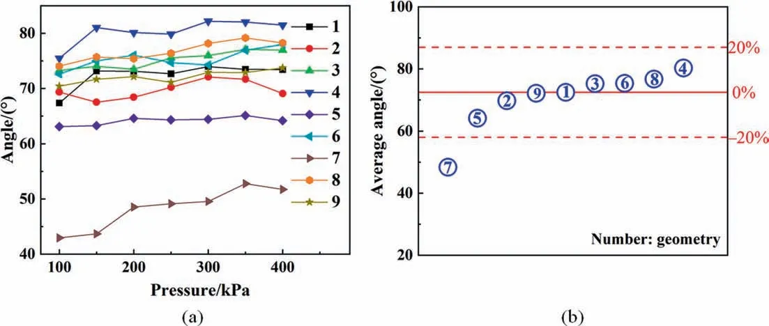
Fig. 11. Spray angle of different nozzles: (a) spray angle of different pressures, (b) average spray angle.
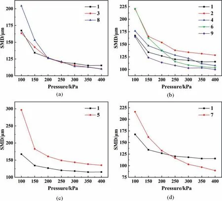
Fig. 12. The relationship between SMD and pressure: (a) group 1, (b) group 2, (c) group 3, (d) group 4.
The average values of the spray angle under different working conditions of the nozzle are shown in Fig. 11(b). The spray angle of nozzle 9 is the same as that of the standard nozzle,so changing the nozzle inlet direction has little effect on the spray angle. The spray angles of nozzles 2,5,and 7 are all smaller than those of nozzle 1, indicating that the three structures all weaken the vortex.Amini [8] found that the spray angle was an inverse function of the nozzle length, which is consistent with the above results. The spray angle of nozzle 7 is significantly reduced, indicating that the nozzle outlet diameter has the greatest influence on the nozzle angle. The spray angles of nozzles 3, 6, 8, and 4 are all larger than those of the standard one, indicating that the structural changes have enhanced the vortex effect.
The influence of different structures on the spray angle was analyzed. The outlet diameter has the greatest influence on the spray angle. The outlet diameter changes the spray angle by more than 20%. Other structures change the spray angle within 20%.
4.1.3. Sauter mean diameter
Atomization fineness is an important indicator to evaluate atomization quality. In this paper, SMD is used as the evaluation indicator of droplet fineness. The SMD of nozzle 10 is close to the limit value of 2000 μm of the test equipment, so the atomization effect is poor. This shows that under low-pressure conditions, the vortex is the necessary atomization condition. The atomization effect cannot be achieved without vortex.
The SMD of nozzle 3 and nozzle 8 are basically the same as that of nozzle 1. The flow and spray angle of the two nozzles are not much different from nozzle 1. This proves that changing the position of the nozzle inlet and the angle of the variable diameter has little effect on the spray. The SMD of nozzle 9 is always smaller than that of nozzle 1.Therefore,changing the nozzle inlet direction will also have a significant impact on SMD. The SMD will be reduced if the downward velocity component is appropriately increased.The SMD of nozzle 2 is always greater than that of nozzle 1.Reducing the length of the swirl chamber will also reduce the SMD. Compared with nozzle 1, nozzles 4 and 6 have an unfixed SMD size relationship.
The discharge coefficients of nozzles 2,4,6 and 9 are the same,and their flow rates are the same under the same pressure. However, the SMD of these four nozzles are different under different working conditions. This proves that under the same flow rate and pressure, the internal structure of the nozzle has a significant impact on the SMD, which needs to be further explored.
In Fig.12,the SMD of nozzle 5 is larger than that of nozzle 1.The structure of nozzle 5 relative to nozzle 1 is changed to increase the inlet diameter.This means that a smaller inlet diameter will correspond to a smaller SMD. The SMD of nozzle 7 was 89.49 μm at 400 kPa, which was the smallest SMD among all the nozzles. In the range of 250 to 400 kPa, the SMD of nozzle 7 is significantly lower than that of nozzle 1. The structure of nozzle 7 relatives to nozzle 1 is changed to reduce the outlet diameter. Reducing the outlet diameter is the most effective way to reduce SMD.However,it also greatly reduces the nozzle flow rate,so it needs to be considered in combination with the actual situation in industrial applications. The reduction of SMD will have a good impact, such as improving the mass transfer efficiency for drying, combustion and chemical reaction.
4.1.4. Comprehensive analysis of atomization effect
From the analysis of the current situation of industrial applications,reducing the SMD and increasing the spray angle is the optimal spray effect. As shown in Fig. 13, taking the SMD and spray angle of nozzle 1 as the dividing line, the SMD above the dividing line is smaller,the spray angle is larger,and the spray effect is better. The SMD below the dividing line is larger, the spray angle is smaller, and the spray effect is worse.
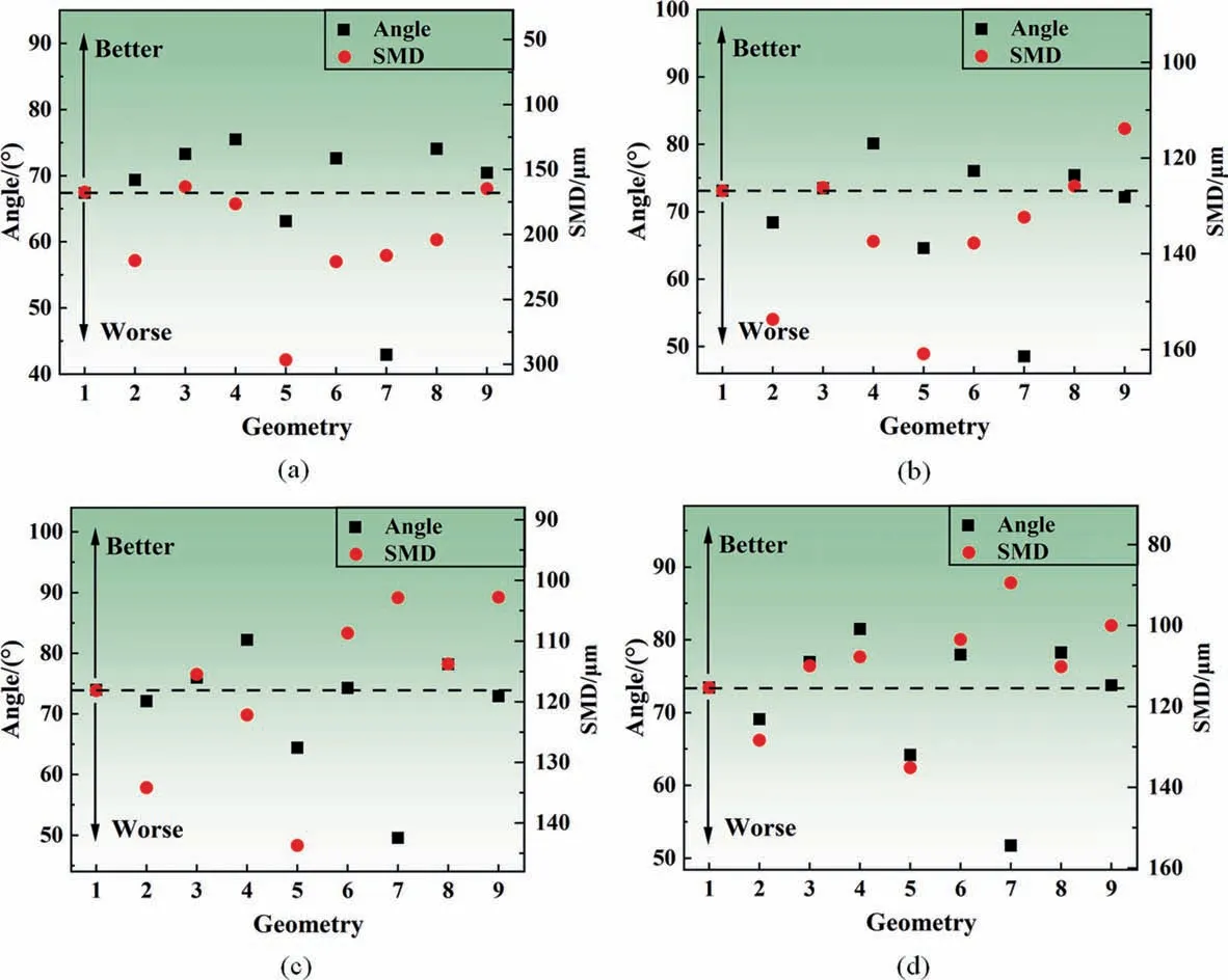
Fig. 13. Comprehensive influence of geometry on spray angle and SMD: (a) 100 kPa, (b) 200 kPa, (c) 300 kPa, (d) 400 kPa.
As shown in Fig.13,it can be summarized into three cases.One is that both the SMD and spray angle enter a better region. For example, with 400 kPa, nozzles 3, 4, 6 and 8 have smaller SMD and larger spray angles,and their comprehensive atomization performance is better. The other is that only one performance has been optimized, and the other performance is worse. The SMD of nozzle 7 is better at 300 kPa and 400 kPa, but the spray angle is smaller. The third case is that both types of performance enter a worse area. Nozzle 5 is in a worse area under all four pressures.In the third case,it can also be considered that changing the geometry in the opposite direction may improve the spray performance.To sum up the above three situations,the two performances of the nozzle can be optimized simultaneously by changing the nozzle structure, and the optimization cost is low.At the same time,only one performance can be optimized, which can also be used for the specific needs of some industrial applications.
4.2. Internal flow field characteristics
4.2.1. Effect of pressure
The variation of pressure with axial distance is analyzed in Fig. 14(a). In the inlet region and the swirl chamber region, the average pressure is basically unchanged. In the variable diameter region, the diameter of nozzle gradually decreases, and the pressure decreases sharply with the increase of the axial distance. At the position of plane 4,the pressures of 100 and 200 kPa are close to 0 kPa, which is close to the atmospheric pressure in the outer area. In the straight edge region, the pressures of 100 and 200 kPa remain unchanged and equal to the outside atmospheric pressure. The pressures under working conditions of 300, 400,and 500 kPa continue to decrease, and the pressures on the plane 5 all reach 0 kPa, which tends to be consistent with the outside atmospheric pressure.
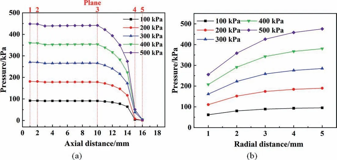
Fig. 14. Pressure varies with axial and radial distance: (a) axial, (b) radial.
In Fig.14(b),it is found that under different working conditions,the pressure increases with the increase of radial distance. The pressure in the central area of the nozzle is low.This is also the reason why the air column is stable.
In Fig. 15(a), the average velocity increases slowly when the axial distance is in the range of 1 to 3 mm.Within the swirl chamber region,the velocity remains constant. In the variable diameter region, the velocity increases as the diameter of the cavity decreases. Plane 4 is the maximum value of speed. At plane 5,due to the influence of air resistance, the swirl intensity decreases and the speed decreases. In Fig. 15(b), with the increase of radial distance, the velocity increases first and then decreases. When the radial distance is large, the velocity value is small due to the influence of the wall. When the radial distance is small,the velocity value is small when it is close to the center of the nozzle.
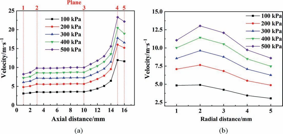
Fig. 15. Velocity distributions in nozzle: (a) axial, (b) radial.
4.2.2. Effect of structure
As shown in Fig. 16, six streamlines from the inlet of nozzles with different structures are drawn.The swirl phenomenon of nozzles 1–9 can be observed clearly. The streamline of nozzle 10 has no swirl characteristics. The intensity of swirling flow inside the nozzle can be judged according to the density of the streamline.The streamline of nozzle 5 and nozzle 7 is thinner than that of nozzle 1,and their swirl intensity is weaker than that of nozzle 1.The streamline of nozzle 8 is denser than that of nozzle 1,and its swirl intensity is stronger than that of nozzle 1. From the experimental results, the spray angle of nozzles 5 and 7 is smaller than that of nozzle 1,while that of nozzle 8 is larger than that of nozzle 1.This shows that using swirl intensity to predict the spray angle is reasonable.
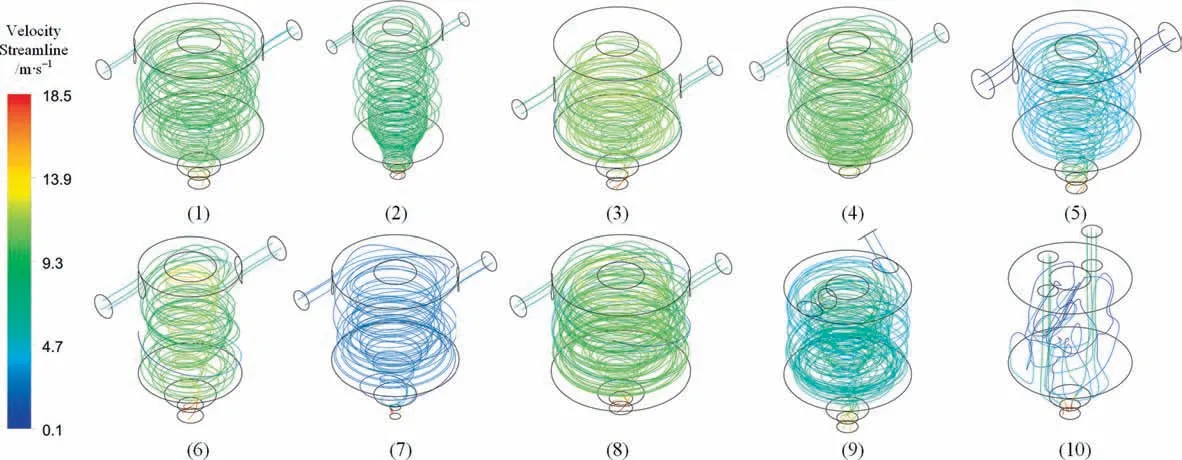
Fig. 16. Streamlines of 10 nozzles.
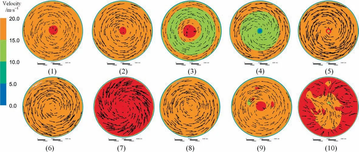
Fig. 17. Flow fields of 10 nozzles.
Fig.17 shows the flow field diagram at plane 4 of different nozzles. It can be seen that nozzles 1–9 has obvious swirl structure.Nozzle 10 has no swirl structure,and the flow direction is chaotic.This verifies that the atomization effect of nozzle 10 is poor because of the no swirl movement. The velocity of nozzle 7 and nozzle 10 is significantly higher than that of other nozzles. The overall flow of nozzle 7 is small due to the small outlet area.Nozzle 10 is the nozzle with the largest flow rate,which indicates that the swirl characteristics will reduce the flow rate of the nozzle to a certain extent.
4.3. Prediction of spray performance
Spray performance is generally obtained through experimental measurements, and spray properties cannot be accurately predicted at the design stage. This also makes it impossible to optimize the nozzle structure according to the requirements.Therefore, if we can predict the spray performance through the simulated data, it will help to some extent for a better design. At the same time, in order to reduce the calculation cost, this paper only simulates the internal domain of the nozzle. Of course, the next important step is to predict the spray performance using the simulated nozzle internal flow field data.
4.3.1. Spray angle prediction
First, the data range used for prediction needs to be selected.Using the average of the overall data may remove some special flow characteristics. Therefore, it is necessary to select feature plane to research. The closer the plane is to the outlet, the more it can show the characteristics of the external flow field.The shape of the air core near the outlet of the nozzle is a cone with a thick bottom and a thin top. From the simulation results, the air core at plane 5 has a large deformation and presents a more unstable condition. The unstable deformation of the air core at plane 4 is small and plane 4 is also close to the nozzle outlet, so plane 4 is selected as the research region. In simulation, the data near the wall and near the air core are of large error. The study area is shown in Fig. 18 after removing the data with large errors.
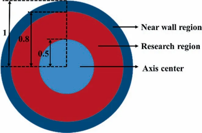
Fig. 18. Nozzle radial section.
In the experimental results, nozzle 10 has no swirl flow, its spray angle is small, and the atomization effect is poor. It can be concluded that the swirl is an important factor affecting the atomization of the single-phase nozzle. There is a dimensionless swirl numberSto judge the strength of the swirl,which is defined as follows [23]:
whereGφis the axial flux of the swirl momentum.Gxis the axial flux of the axial momentum. The radius of the circular section isR.UandWare the axial and tangential velocities of the swirl nozzle.Scan be calculated from the flow field data obtained by simulation.
In the experiment, under the same pressure, the flow rates of nozzles 2, 4, 6 and 9 are the same, but the spray angle and SMD are different.It is proved that the geometric structure has obvious influence on the atomization effect. This paper mainly studies the pressure swirl nozzle. The liquid phase enters the nozzle tangentially along the wall. It mainly does a simple swirl motion. Swirl numberSis an important dimensionless number affecting the swirl motion[23].The swirl motion inside the nozzle will produce centrifugal force.After the liquid phase is ejected,it will no longer be bound by the nozzle cavity. Under the action of centrifugal force,it is expanded into a conical liquid film with a certain angle.The angle of the liquid film is the ratio of radial and axial momentum. The swirl numberShas a great influence on the swirl atomization process.
As shown in Fig. 19, nozzles 2, 9, and 6 show that the spray angle increases with the swirl number. The structure of nozzle 4 is changed to remove the straight edge at the outlet, soScannot explain the influence of the straight edge.
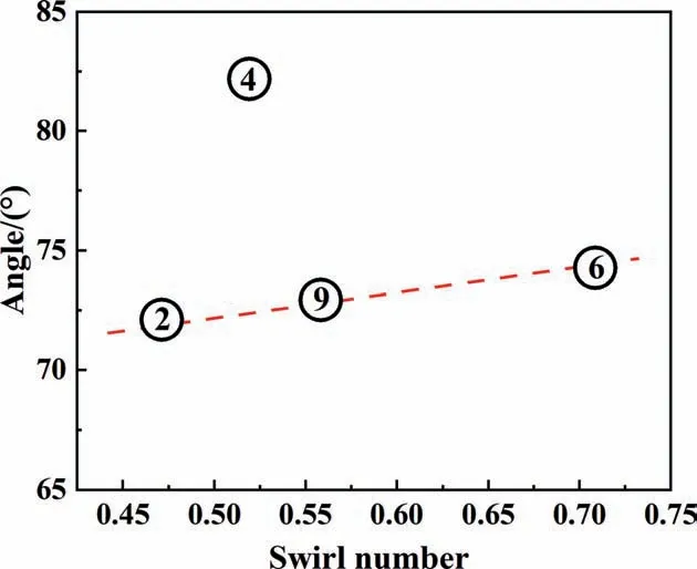
Fig. 19. Relationship between spray angle and swirl number.
Wanget al. [37] used multivariate nonlinear fitting method to establish a mathematical model for nozzle prediction. The fitted variables were working conditions and geometry parameters. The fitting effect was good.The goal of this paper is to predict atomization characteristics using simulated data. Working conditions and geometry have been considered and reflected in the simulation data, and this paper uses univariate to predict nozzle atomization performance. Therefore, the method of nonlinear fitting is used in this work.
The data of nozzles 1,2,3,5,6,7,8 and 9 under the pressure of 100, 200, 300 and 400 kPa are analyzed. Fig. 20(a) shows the relationship between spray angle andSin these 32 groups of data.A novel empirical equation for the spray angle of swirl nozzles is fitted from the experimental results and simulations, which only includes the effect ofS. The data of nozzle 4 is excluded from the fitting data. The goodness of fittingR2is 0.8689. All data points are within the 15% error line.
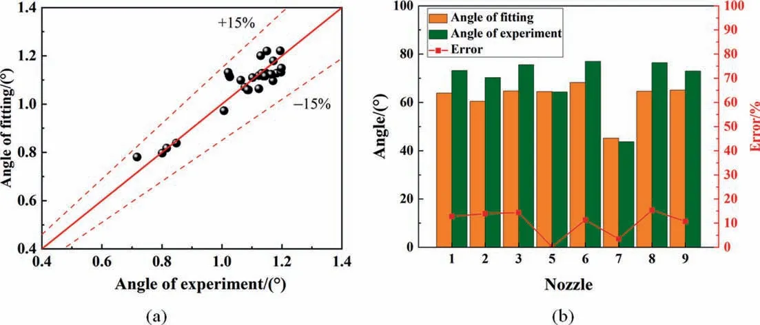
Fig. 20. (a) The comparison between the experimental angle and the fitted angle. (b) Verification.
The fitting equation is universal under the above conditions,which verifies the feasibility of using swirl numberSto predict spray angle.
The experimental and simulation data under three pressures of 150,250 and 350 kPa were selected for the validation of the equation.The prediction accuracy of the equation is shown in Fig.20(b),and the error is within 15%.The prediction accuracy of nozzle 5 and nozzle 7 is relatively high, which indicates that the equation is more suitable for the prediction with the change of inlet and outlet diameters.
4.3.2. SMD prediction
The initial atomization of spray is related to the unstable breakup of liquid sheet, which has a significant impact on the SMD [38]. Stähleet al.[39] mentioned that the energy concept showed to be an appropriate method for the prediction of SMD.Turbulent kinetic energy is a key factor characterizing the energy characteristics of turbulent flow. At the same time, turbulent kinetic energy (k) indicates the intensity of turbulence. The instability of turbulence is one of the influencing factors of liquid film breakage.Therefore,turbulent kinetic energy may be an important factor affecting the performance of SMD.
As shown in Fig. 21, nozzles 2, 4 and 6 show that the SMD decreases with the increase of turbulent kinetic energy,but nozzle 9 does not conform to this.Therefore,turbulent kinetic energy may be applicable to predict the SMD except nozzle 9. Nozzle 9 structurally changes the inlet direction of the nozzle. The flow changes from horizontal flow to downward flow, thus increasing the axial momentum inside the nozzle. Turbulent kinetic energy can only indicate the turbulence intensity of the liquid, and cannot reflect the characteristics of the axial momentum of the nozzle.Therefore,the flow field characteristics of nozzle 9 cannot be shown by the turbulent kinetic energy, and the turbulent kinetic energy cannot be used to predict this type of nozzle.
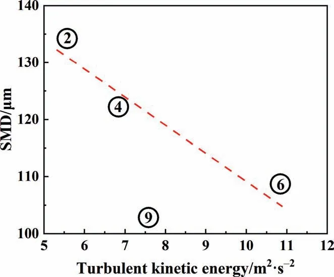
Fig. 21. Relationship between SMD and turbulent kinetic energy.
Nozzles 1,2,3,4,5,6,7 and 8 at 100,200,300 and 400 kPa are used for fitting between SMD and turbulent kinetic energy. It is found that single factor can’t achieve its accurate prediction.Therefore, factors such as nozzle inlet diameter and nozzle cavity diameter are added to the fitting equation. The fitting equation with certain accuracy is obtained. The goodness of fittingR2is 0.8748. All data points are within the 20% error line, as shown in Fig. 22(a).
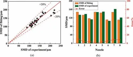
Fig. 22. (a) The comparison between the experimental SMD and the fitted SMD. (b) Verification.
The data under three pressures of 150, 250 and 350 kPa were also used for the validation. The prediction accuracy of the equation is shown in Fig. 22(b), and the error is within 10%. The SMD prediction accuracy of nozzles 2, 3, 4 and 5 is relatively high. The relative size relationship of SMD of different nozzles can also be accurately judged by the fitting equation.
5. Conclusions
In this paper,the influence of the internal structure on atomization was explored by testing 10 designs of pressure swirl nozzles.Combined with the simulation of the flow inside the nozzle, the prediction of spray performance can be partly achieved.The specific conclusions are as follows:
(1) Experimentally, the flow of 10 nozzles all increased with increasing pressure. The swirling flow inside the nozzle reduces the flow rate. The diameters of the nozzle inlet and outlet have a greater impact on the flow rate. The larger the diameter of either inlet or outlet,the lower the resistance and the larger the flow rate.Changing different nozzle structures may have the same effect on the flow rate, which means the same discharge coefficient.
(2) When the pressure is greater than 100 kPa, the spray is nearly fully expanded, and the spray angle increases slightly with the increase of pressure. No swirl nozzles have a very small spray angle and poor spread. The outlet diameter has the greatest influence on the spray angle, and reducing the outlet diameter greatly reduces the spray angle. Removing the straight edge area of the outlet can slightly increase the spray angle. Increasing the inlet diameter can reduce the spray angle by a small amount. Changing other structures has little effect on the spray angle.
(3)As the pressure increases,the SMD of each nozzle decreases gradually. The internal structure of the nozzle has a significant effect on the SMD.Increasing downward momentum reduces spray particle size.Reducing the outlet and inlet diameter can effectively reduce the spray particle size. Swirl is the key factor for nozzle atomization, and the atomization effect of the structure without swirl is poor. With the same flow rate and pressure, the internal structure of the nozzle has a significant impact on SMD.
The influence of geometric structure on atomization particle size and spray angle was comprehensively analyzed. Changing the geometry improves both SMD and angle performance. At the same time, changing different geometries has different effects on the SMD and angle, providing the possibility to customize nozzles for specific needs in industrial applications.
The pressure and velocity distribution of the internal flow field of the nozzle can be obtained by numerical simulation. The flow field differences of nozzles with different structures can be compared.The velocity and pressure characteristics are consistent with the experimental phenomena. Through the characteristics of the internal flow field,it can be determined that the nozzle mainly performs swirl motion.The streamline density can well represent the swirl strength.
It is feasible to predict the spray angle and the SMD by using the simulated data of the flow inside the nozzle.The spray angle can be predicted by the swirl numberS. The SMD can be predicted by combining turbulent kinetic energy with geometric parameters.Empirical evidence that the prediction error is within 15% and 10%respectively.The equation fitted in this paper has some limitations in terms of operating conditions and nozzle types,and its universality needs to be further improved.
Declaration of Competing Interest
The authors declare that they have no known competing financial interests or personal relationships that could have appeared to influence the work reported in this paper.
Acknowledgements
This work was supported by the National Key Research and Development Program (2022YFB3504000), the National Natural Science Foundation of China (22122815, 21978296), the NSFC-EU project(31961133018),and the Youth Innovation Promotion Association CAS is gratefully acknowledged.
Supplementary Material
Supplementary data to this article can be found online at https://doi.org/10.1016/j.cjche.2023.05.002.
Nomenclature
Aarea of outlet, m2
Cddischarge coefficient
C1ε,C2ε,C3ε coefficient ink–ε equation
d1inlet diameter, mm
d2swirl chamber diameter, mm
d3outlet diameter, mm
Gxaxial flux of the axial momentum
Gφaxial flux of the swirl momentum
h1swirl chamber height, mm
h2inlet height, mm
h3outlet straight edge height, mm
kturbulent kinetic energy, m2∙s-2
Oorigin of coordinates
ppressure, kPa
Qflow rate, L∙min-1
Rradius of circular section, m
rradial coordinate, mm
Sswirl number
SMD Sauter mean diameter,μm
Uaxial velocity, m∙s-1
Wtangential velocity, m∙s-1
zaxial coordinate, mm
α spray angle, (°)
θ angle of variable diameter region
ρlliquid density, kg∙m-3
 Chinese Journal of Chemical Engineering2023年11期
- Chinese Journal of Chemical Engineering的其它文章
- Effects of the original state of sodium-based additives on microstructure,surface characteristics and filtration performance of SiC membranes
- Comprehensive analysis on the economy and energy demand of pressure-swing distillation and pervaporation for separating waste liquid containing multiple components
- Esterification of acetic acid with isobutanol catalyzed by ionic liquid n-sulfopropyl-3-methylpyridinium trifluoromethanesulfonate:Experimental and kinetic study
- Numerical investigation of film forming characteristics and mass transfer enhancement in horizontal polycondensation kettle
- COF-derived Co nanoparticles@N-doped carbon electrocatalysts for highperformance Zn-air batteries
- A potential-responsive ion-pump system based on nickel hexacyanoferrate film for selective extraction of cesium ions
