Progress in research of process intensification of spouted beds:A comprehensive review
Jiali Du,Feng Wu,Xiaoxun Ma
School of Chemical Engineering, Northwest University, Xi’ an 710069, China
ABSTRACT The development of intensification technology for spouted beds has become a current research focus,and an effective way to improve the efficiency of spouted beds is to reform their structure.Although numerous studies have been conducted on conventional beds,there are few reviews on the comprehensive application of intensification technology for spouted beds.In this paper,we comprehensively review the role of intensification technology in spouted beds for use in hydrodynamics,drying,desulfurization,pyrolysis,coating,biomass and waste gasification,and biomass drying from the perspective of experiment and simulation.Finally,potential problems and challenges in current spouted-bed research are summarized.
1.Introduction
Spouted beds are a special type of fluidized bed that originated in Canada and were originally designed for drying large particles such as wheat [1].The design of spouted beds represents a transformation of fluidized beds,but they are significantly different from fluidized beds,particularly in terms of the flow pattern of the particles.The particles in a fluidized bed are irregularly distributed in a fluidized state,whereas the gas–solid contact efficiency of large particles in a spouted bed is relatively high,and the operating pressure drop is low.Spouted-bed technology is attracting increasing attention owing to its simple structure,low pressure,and excellent heat and mass transfer characteristics [2–6].With the development of science and technology and the deepening of innovation consciousness,the application fields of spouted beds have been extended to drying [7–9],pyrolysis[10,11],gasification [12,13],oxidation [14],coating [15],desulfurization [16],and so on.
However,with the improvement in industrial production requirements,the requirements for spouted-bed technology have become increasingly stringent,revealing limitations to conventional spouted beds.The size of a conventional spouted bed cannot be expanded to meet the requirements of large-scale drying because of structural limitations.In addition,it is difficult to dry small-size materials,and the pressure loss at the central nozzle of the bed is large [17,18].In the process of desulfurization,the radial mixing of a gas and a solid in the spout and annular regions of a conventional bed is insufficient,and inactive or dead zones can easily exist,resulting in low desulfurization efficiency [19,20].In the process of pyrolysis,bed blockage and low efficiency are often encountered[19,21].The need for good mixing of heat carriers and pyrolytic substances through the carrier gas in the equipment limits the long-term development of conventional beds,and the pyrolysis performance is vulnerable to particle agglomeration,leading to flow separation.In some cases,it is helpful or even essential to optimize the spouted-bed structure to promote or enhance the operation and utility of the bed for a particular application.Currently,there are draft-tube spouted beds [22–24],multi-jet spouted beds [25],internal circulation spouted beds [26,27],spout-fluidized beds[28,29],and spouted beds with further structural optimization,including novel types of spouted beds with longitudinal vortex generators (LVGs),spouted beds with integral swirling blade nozzles (ISBNs),and an integral multi-jet spoutfluidized bed (IMJSFB) that we are working on.
Although numerous studies have been conducted on spouted beds,little is known about the comprehensive application of enhanced spouted beds,despite their proven advantages in different application fields.Numerical simulations and experiments are two different methods of investigating spouted beds,both of which have their own characteristics and advantages.At present,many novel enhanced spouted beds are only in the simulation stage because of their structural particularity and high experimental cost.Compared to experimental studies,numerical methods areless costly and can predict parameters that are experimentally unmeasurable.Therefore,this paper creatively reviews the intensification technology for spouted beds from the perspectives of experiment and simulation.Furthermore,the application of different spouted beds in the fields of drying,desulfurization,pyrolysis,coating,biomass and waste gasification,and biomass torrefaction are reviewed in detail to provide readers with the latest knowledge of spouted bed reactors.It therefore provides a theoretical basis and useful guidance for in-depth research of the novel intensification technology of spouted beds in some frontier fields and permeation disciplines.Finally,perspectives on the future development of spouted beds are highlighted.
2.Basic Structure and Classification of Spouted Beds
2.1.Basic structure of conventional spouted beds
After more than half a century of development,spouted beds come in many forms,but the most typical is the conventional conical spouted bed,which is composed of three main parts: the nozzle,the bottom inverted cone,and the cylindrical main body;its basic structure is shown in Fig.1.The spouted bed is filled with particles,and gas is injected from the inlet at the bottom of the bed,forming a powerful jet in the middle of the bed.When the velocity of the gas exceeds the critical velocity,it forces a path through the particles to form a dilute-phase spout region in the center of the bed where the particles move upward.After the particles reach a certain height,their velocity decreases under the action of gravity and they fall back down,forming a fountain-like region.Around the spout region,continued particle circulation owing to gas flow creates an annular region with densely packed particles[30,31].This type of flow with a spout,annulus,and fountain region is known as the spouting phenomenon of the spouted bed.The spouting phenomenon exists only within a limited range of flow velocities.If the velocity is too low,a complete spout region cannot be formed,and if the velocity is too high,the entire bed is fluidized.

Fig.1. Schematic diagram of the basic structure of conventional spouted bed.
The spouting phenomenon of different spouted beds is related to the operating parameters,and different operating parameters lead to different particle flow characteristics.The main factors used to evaluate the hydrodynamic characteristics are as follows:minimum spouting velocity (Umin),maximum spouting height (Hmax),maximum spouting pressure drop (ΔPmax),minimum fluidization velocity (Umsf),etc.The velocity required for the fluid to reach a stable spouting state in the bed is calledUmin.Uminis critical in industrial design applications,which will affect the selection of materials and the design of bed structure size.When the structure of the spouted bed is determined,the particles accumulated in the bed have a maximum spouting height,which is calledHmax.If the filling height of the particles in the bed exceeds the maximum limit,the flow pattern of the particles in the spouted bed will be transformed into bubbling or throbbing,so it is optimal when the filling height of the material is less thanHmax.AndHmaxreflects the capacity of the bed to handle the material.ΔPmaxis the pressure drop of the bed from the initial static state to the steady state,phases in the spouted bed is transformed from the initial static state to the frictional collision between the gas and the phase,which causes the pressure loss in the bed.Umsfis the velocity at which the particles change from a static state to a fluidized state as the flow velocity increases when the fluid passes through the bed.Table 1 summarizes empirical correlations and semitheoretical models forUmin,Hmax,ΔPmaxandUmsfin different types of spouted beds [32–45].
2.2.Classification of spouted beds
2.2.1.Classification by bed section
Driven by different industrial applications,researchers have designed modified spouted beds with different structures to meet production needs.According to the number of sections of the beds,spouted beds can be divided into rectangular,two-dimensional,and cylindrical.
(1) Rectangular spouted beds
Conventional conical spouted beds have been shown to be more efficient in terms of the gas–particle contact of coarse Geldart D particles,but they suffer from scale-up limitations,such as the inability to achieve high-quality jets in larger cells.The performance of such beds is unpredictable when the diameter is larger than 0.3 m[46];thus,they are rarely used in large-scale industrial processes.Mujumdar [47] proposed a spouted bed with a rectangular cross section that was initially operated in batch mode to eliminate the scale-up disadvantage,and different flow regimes could be achieved by simply changing the inlet nozzle size.The scalability of a rectangular spouted bed can be achieved by increasing its size or connecting multiple units in series,which is also beneficial for continuous operation[48].The multi-compartment slotrectangular spouted bed helps increase its potential for industrial applications [49].Reyeset al.[50] experimentally investigated the results of the continuous drying of sawdust with three tandem solar rectangular spouted beds and concluded that at a 95% confidence level,the significant effects of steady-state operation were sawdust feed flow,solid initial moisture content,and drying air temperature.
(2) Two-dimensional spouted beds
To overcome the difficulty in scaling up conventional spouted beds,Mujumdar [47] proposed a two-dimensional spouted bed consisting of a flat wall with a sloping base and an air inlet slot along the center of the bed width.This configuration was renamed slotrectangular spouted beds by Doganet al.[51] and Freitaset al.[52].The rectangular geometry provides an easy solution for increasing throughput.The geometrical properties of the twodimensional spouted bed increase the application of this bed in drying particulate solids.Passoset al.[39]analyzed and quantified the spout termination mechanism in a two-dimensional spouted bed using dimensionless parameters,derived a new correlationfor the maximum spout height in coarse-grained two-dimensional spouted beds,and discussed the bed scale-up criteria.To stabilize the circulation of solids and reduce the bed pressure drop,draft plates are typically inserted to separate the spout region from the downcomer region.Kudraet al.[53]used the discrete element method (DEM) to study the particle aerodynamics and gas-toparticle heat transfer in a two-dimensional spouted bed with draft plates.The particle circulation rate increased as the coefficient of friction decreased or separation height increased,and the draft plates reduced the minimum injection velocity and pressure drop[54].

Table1 Empirical correlations and semi-theoretical models for Umin, Hmax,ΔPmax and Umsf
(3) Cylindrical spouted beds
For cylindrical spouted beds,San Joséet al.[55]used an optical fiber probe to study the geometric shape of the dead region (stagnant solid)and the spout region.The results showed that the position and size of the spout depended on the geometric factors of the contactor and the operating conditions.Based on the Eulerian–Eulerian two-fluid model combined with the granular kinetic theory [56],the hydrodynamics of a cylindrical spouted bed were investigated,and the representative unit cell resistance drag and viscosity models were found to be most suitable for predicting the gas and solid flow patterns.Xiaoet al.[57] surveyed the solid circulation flux and gases in a half-cylindrical pressurized spoutfluid bed with a draft tube.Through experimental methods,the minimum spouting speed,axial pressure drop,and fountain height data were obtained for a visible pressurized cylindrical spout-fluid bed.
2.2.2.Classification by process requirement
According to the requirements of the production process,spouted beds can be further divided into draft-tube spouted beds,multi-jet spouted beds,internal circulation spouted beds,and spout-fluidized beds.The following subsections discuss each of these types of spouted beds [58].

Fig.2. Schematic diagram of draft-tube spouted bed.
(1) Draft-tube spouted beds
In a conventional spouted bed,a considerable amount of the injected gas enters the annular region,which increases the residence time of the gas in the spouted bed.Obviously,this is extremely disadvantageous for operations that require precise control of gas residence time.Draft tubes are therefore widely used in spouted beds.As shown in Fig.2 [59],a draft tube is inserted in the spout region to prevent the gas and solid phases from passing through,which can greatly reduce or even eliminate the interactive flow between the spout and annular regions.After the draft tube is inserted,the airflow and material movement are more regular,which helps achieve stable fluidization of materials that are difficult to spout.In addition,it can reduce pressure drop and power consumption [60].
At present,scholars have conducted in-depth research on drafttube spouted beds and have made significant progress.The flow behaviors of particles in a two-dimensional spouted bed with porous draft plates were studied using fluid dynamic computation with kinetic–frictional stress models [61],and it was found that the solid circulation rate in a spouted bed with a porous draft tube is greater than that with a nonporous draft tube.Mollicket al.[62]studied the solid circulation rate by changing the spouted gas velocity in a draft-tube spouted bed.With increasing distance between the draft tubes,the minimum value of the circulation velocity also increased,and the spouting stability significantly improved with the draft tube[63].The jetting efficiency also significantly improved under the influence of a draft tube [64].Wanget al.[65] studied the flow behavior of particles in a spouted bed with a draft tube using a continuous kinetic–friction stresses model,the particle concentration and velocity distribution in the spouted bed with a draft tube were predicted.Using the Eulerian–Lagrangian method,Yanget al.[66] concluded that the draft tube improved the relative velocity between gas and solid to a certain extent and reduced the overall circulation of the bed.In a draft-tube spouted bed,an acoustic field can reduce the critical transition velocity of the flow pattern and the minimum fluidization velocity in the annulus region,thereby increasing the operational flexibility [67,68].The flow characteristics of ultrafine powder agglomerates in the bed were analyzed by numerical simulation,and it was found that a sound field can effectively inhibit the bypass of the fluidized gas and significantly reduce the bypass fraction of the fluidized gas [69].
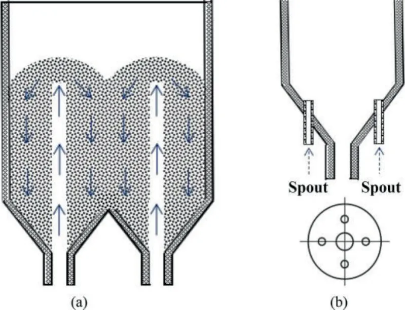
Fig.3. Schematic diagram of multi-jet spouted bed.
(2) Multi-jet spouted beds
A multi-jet spouted bed provides several jets at the bottom of a traditional spouted bed for the fluid to enter,thereby increasing the fluid flow and improving the processing capacity of the bed.Multi-jet spouted beds are mainly divided into two categories.In one,a nozzle is configured in each bed chamber,and each bed chamber is connected to the other,as shown in Fig.3(a).In the other,multiple jets are placed in one bed chamber,as shown in Fig.3(b).Owing to the increase in the number of nozzles and the presence of multiple chambers,the limitation of the spout region diameter can be alleviated,thereby increasing the processing capacity of the spouted bed and improving the thermal efficiency.This type of spouted bed is particularly suitable for small-particle granulation systems.Another advantage of multi-jet spouted beds is that,for materials that require multi-stage operation,many intermediate links can be omitted,such as solid transportation.For conditions involving wet material sticking to the wall,the contact between the material and the wall can also be reduced.In a double-nozzle rectangular spouted bed,the minimum spouting velocity is related to the particle size,bed height,and temperature[70].An empirical correlation of the Reynolds number can be obtained under the working conditions of the minimum spouting velocity.The minimum velocity of the airflow at the nozzle of the multi-nozzle spouted bed is related to the material properties but not to the number of nozzles [71].
(3) Internal circulation spouted beds
In an internal circulation spouted bed,the gas inlet nozzle at the bottom of the spouted bed is connected to the draft tube.There are multiple small holes on the side wall of the tube for the solid particles to pass through,which increases the mixing movement between the particles.A schematic of the structure is shown in Fig.4.The particles move to the top of the tube under the action of gas fluidization,and the ‘‘T”-type separation device at the top of the draft tube performs inertial separation of the gas and the particles.An internal circulation spouted bed can promote the local mixed flow of internal particles and improve the circulation between the solid particles in the bed[72].Different feeding methods also have different effects on the mixing flow of particles in an internal circulation spouted bed [73].The use of face-feed and under-feed systems can distribute the materials on the cross section of the bed more uniformly,especially at the bottom water spout humidification region,and improve the gas–solid mixing.Adopting an under-feed system further optimizes the flow field distribution in the reactor and provides for uniform gas radial velocity [74,75].
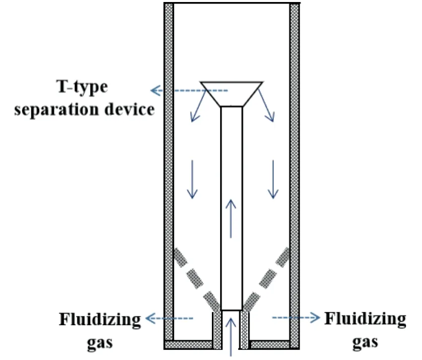
Fig.4. Schematic diagram of internal circulation spouted bed.

Fig.5. Schematic diagram of spout-fluidized bed.
(4) Spout-fluidized beds
To remove inactive or dead zones,thereby preventing particle agglomeration,a distributor is added at the side wall of the conical area.The sparging gas entering from the bottom of the spouted bed and the fluidizing gas entering the side wall jointly fluidize the particles to form a spout-fluidized bed,as shown in Fig.5.The addition of the distributor promotes the mixing of particles and gas in the annulus region,reduces the local aggregation of particles [76,77],and improves stratification or throttling in the bed.The spoutfluidized bed has the advantages of both spouted and fluidized beds in that it intensifies the mass and heat transfer between the gas and the particles and increases the bed’s thermal efficiency.Fuet al.[78] used different materials to conduct an experimental study on the maximum spouting pressure drop of a spoutfluidized bed.Zhaoet al.[79] used the Eulerian–Eulerian twofluid model to numerically simulate the gas–solid flow process in a spout-fluidized bed and obtained the flow patterns at different speeds and the distribution of the granular temperature in different regions.Zhonget al.[80] experimentally studied the hydrodynamic properties in a high-pressure cylindrical spout-fluidized bed and systematically analyzed the influence mechanism of the pressure drop,minimum spouting velocity,and fountain height.
3.Hydrodynamic Characteristics
Hydrodynamics plays an important role in the operation and application of spouted beds [81].As a branch of fluidization technology,the structural characteristics of conventional spouted beds have some limitations,such as insufficient gas–solid mixing,dead zone of flow at the bottom of the annulus region,and insufficient circulation leading to uneven heating of materials,which leads to the low processing efficiency of spouted beds in industrial applications.Many researchers have carried out structural modification of conventional spouted beds and conducted in-depth research on the hydrodynamic characteristics,which are the basis for the quantitative design,optimization,and rational scale-up of various spouted bed reactors and important for evaluating mass and heat transfer.Table 2 summarizes the application of different spouted beds in hydrodynamic characteristics.

Table2 Application of different spouted beds in hydrodynamic characteristics
To achieve continuous external convection heat and mass transfer with high intensity,Devahastinet al.[82]developed a new type of rotating jet annular spouted bed;a schematic diagram of the overall experimental apparatus is shown in Fig.6.The gas–solid contactor consisted of a rotating spouting air jet in the annular region of a cylindrical vessel.The hydrodynamic characteristics and the effects of the jet rotational speed,bed height,nozzle diameter,as well as those of particle size,shape,and density,on the minimum spouting velocity,peak pressure drop,and steady-jet pressure drop were determined experimentally.Empirical correlation was used to predict the values of the key hydrodynamic parameters to design and scale up the reactor.In response to the problem of uneven heating of materials owing to insufficient material circulation in the annulus region with increasing bed diameter,Xu and Liu [83] proposed the concept of a spouted bed with a rotating draft tube and conducted an experimental study on the fluid flow in the bed.It was found that the high-speed airflow drove the material into the draft tube,which was rotated at a constant speed,fully diffusing the material so that it was evenly sprayed in the surrounding annular gap region.Chen and Zhang[84] used rapeseed as a raw material to further discuss the fluid dynamics of a spouted bed with a rotating draft tube;the fluid mechanics experimental device is shown in Fig.7.The authors reported the relationship between the air superficial velocity and pressure drop,starting pressure drop and draft-tube jet distance,and solids circulating and air superficial velocities at different draft-tube jet distances.This novel spouted bed sprayed the material in a wider range according to the velocity of the material spraying out of the draft tube during the test,but its amplification effect requires further study.
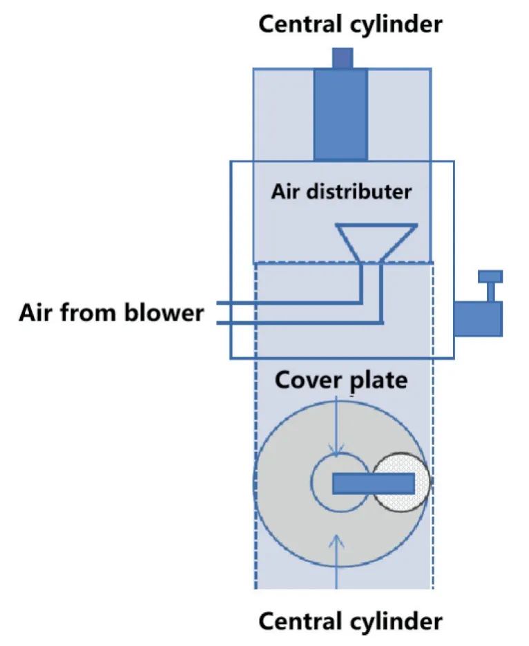
Fig.6. Schematic diagram of the overall experimental apparatus.
Enhancing the flow of particles and eliminating stagnation in the annular region are the keys to improving the flow performance of the rectangular spout-fluidized bed,and many researchers have introduced deflectors in the bed.A novel annular spouted bed was developed at Shanghai Jiao Tong University [85,86].The bed consisted of two homocentric upright cylinders with different diameters,multiple nozzles,and V-shaped deflectors installed at the bottom of the annular region between the inner and outer cylinders.According to the particle flow behavior along the direction of the bed height,the spouted bed can be divided into three different regions,as shown in Figs.8 and 9 [91]: (1) the moving packed zone in the V-shaped deflectors,(2) the dense-phase spouting fluidization zone,and (3) the dilute-phase zone at the top of the annular region.Compared with a conventional spouted bed,the annular spouted bed has the advantages of good mixing effect,high gas–solid heat-transfer rate,high unit air particle load,and suitability for regenerative heat exchangers [92,93].The V-shaped deflectors keep the particles moving horizontally and easily control the fluid residence time and solids circulation time [94,95],but they cut off free exchange through the nozzle ring boundary,reducing the solids circulation velocity[66].Improved draft tubes,both porous and open-sided draft tubes [87],can greatly expand the operating range of the jet,stabilize it,and reduce its negative impact on the solids circulation rate.As the most widely used internal baffle in spouted bed applications,the draft tubes can maintain the horizontal movement of particles,and also easily control the fluid residence time and solid circulation time [96].Yueet al.[88] implanted an umbrella-like baffle in a rectangular spouted fluidized bed,conducted a simulation study on its hydrodynamic characteristics,and found a new flow pattern called multi-stage spouting,as shown in Fig.10.The spout channel is divided into two stages by the baffle,denoted as the first spouting(below the baffle) and the second spouting (above the baffle).It was also found that multi-stage spouting has obvious advantages in nozzle robustness and gas–solid mixing performance.
The effects of inlet spouting fluid and fluidizing fluid velocity on particle flow in a draft tube spouted fluidized bed were studied,and the optimal structure and operating conditions of the bed were obtained [89].The velocity of the inlet spouting fluid had little effect on the particle distribution and only accelerated the circulation of particles in the annulus region and draft tube.However,with increasing fluidizing fluid velocity,the distribution of particles in the annulus region became more uniform,the particle concentration decreased,and the circulation speed increased.Guoet al.[90] used computational fluid dynamics (CFD)-DEM to study the hydrodynamics and heat-transfer characteristics of dry and wet particles in a quasi-two-dimensional IMJSFB.As shown in Fig.11,under the impact of the side jets,the height of the fountain was reduced compared with that of a conventional spouted bed,the spout region increased,and the particle movement was intensified.It is thus concluded that the IMJSFB has obvious advantages in terms of particle circulation characteristics and wet-particleprocessing.
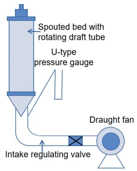
Fig.7. Schematic diagram of fluid mechanics experimental device.

Fig.8. The spouting and fluidizing phenomenon in annular spouted bed.Reproduced from Ref.[91] with permission of Elsevier,copyright 2008.
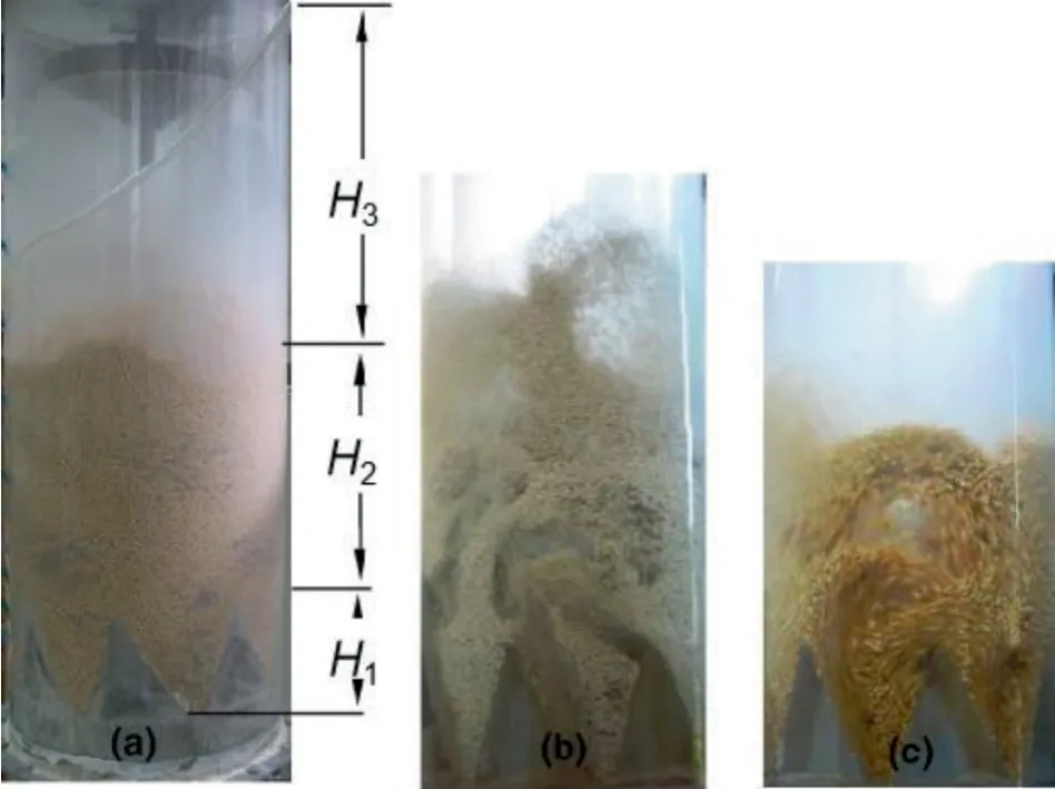
Fig.9. Typical photographs of particle flow in an annular spouted bed for different nozzle structures: (a) forward nozzles,soy beans;(b) angle nozzles,polyethylene beads;and (c) angled nozzles,corn.Reproduced from Ref.[91] with permission of Elsevier,copyright 2008.
Analysis of previous publications on hydrodynamic characteristics shows that the numerical simulation method is more convenient for studying the hydrodynamics of various spouted beds.It is necessary to achieve a good balance between experimental and simulation methods.
4.Application Progress of Enhanced Spouted-bed Technology
In recent years,spouting intensification technology has played an irreplaceable role in the fields of drying,desulfurization and pyrolysis,coating,biomass and waste gasification or biomass torrefaction,etc.
4.1.Drying field
Spouted beds have the advantages in terms of uniform mixing and sufficient gas–particle contact,making them optimal dryers[97].Drying of particles is an important operation in industry for improving product quality and reducing energy consumption.Various improved spouted beds have been developed for this purpose,such as a rotating draft-tube spouted bed [98],rotating draft-tube spouted bed with a porous branch pipe [99],triangular spouted bed [100],pneumatic spouted bed [101],internal heating pneumatic spouted bed[102,103],spouted bed with an open helicoidal conveyor screw placed [104,105],swirling fluidized-bed dryer[106],spouted beds with guide tubes (tubeless,non-perforated,and open tubes)[107,108],etc.Table 3 summarizes the application of different spouted beds in drying field.
A draft-tube spouted bed has the advantage of eliminating the alternating flow between the spout and annular regions,improving the adaptability of particles,and reducing the pressure drop;however,scaling up its industrial application is still difficult.To eliminate the technological bottleneck of scaling up draft-tube spouted beds,Li [98] proposed a rotating draft-tube spouted bed (Fig.12).The rotating draft tube evenly sprinkles the material on the periphery of the annular gap region,reducing the‘‘dead zone”condition.Also,the material is sprayed horizontally or obliquely to keep it from falling back into the draft tube,which is what occurs with vertical spraying.In addition,this structure has the advantages of scalability,increased bed volume,and improved production capacity and drying quality.However,this structure was proposed on the basis of a small spouted bed;the flow pattern in the annular region of a larger bed requires further study.If the problem of reactor enlargement can be solved,this novel type of spouted bed could become a grain dryer with good prospects.In a similar study,Sun[99]connected a porous branch pipe to the rotating draft-tube of a spouted bed;the schematic diagram is shown in Fig.13.The effects of the porosity percentage,draft-tube distance,air temperature,and air volume on the grain temperature and drying rate were studied.With increasing air volume,the drying rate gradually increased,and the grain temperature showed an upward trend.Within a certain range,the drying air temperature was proportional to the drying rate and grain temperature.Within the range of the selected draft-tube distance,the drying rate was less affected,but the grain temperature was significantly affected.The drying rate of the material and the increase in grain temperature with the porous branch pipe were significantly greater than those without the pipe,thus enhancing the gas–solid contact and promoting mass and heat transfer.A triangular spouted-bed dryer can provide more benefits in terms of cost reduction and energy savings.Goet al.[100] established a mathematical model for the temperature and moisture content distribution of wheat in a triangular spouted-bed dryer.Based on this model,they analyzed the mass and heat transfer in the bed.In addition,an empirical bulkdensity model for wheat was developed that could accurately predict the moisture content of wheat during drying.However,at high temperatures,owing to the heat loss in the drying process,the accuracy of the temperature prediction in the triangular spouted bed needs to be improved,and further research is needed to improve the accuracy of this model.

Fig.10. Snapshots of voidage in multi-stage and normal spouting: (a) multi-stage spouting case, u=90 m∙s-1;(b) normal spouting case.Reproduced from Ref.[88] with permission of Elsevier,copyright 2021.

Fig.11. Simulations of particle flow patterns from the static situation to stable spouting in (a) IMJSFB and (b) conventional spouted bed.
With the implementation of more stringent product quality requirements,it is difficult to meet the demand for independent spouted-bed drying.In view of the advantages and disadvantages of spouted beds and airflow duct drying,Wang [101] combined the two organically by designing a‘‘round sky and place”structure as a pneumatic spouted-bed experimental platform,and the flow characteristics and drying performance of the equipment were experimentally investigated.The basic structure of the device is shown in Fig.14.An airflow pipe is inserted in the center of the structure for material transportation and preliminary drying.At the upper end of the pipe is a cylindrical spouted bed in which the materials are spouted,and at the bottom of the spouted bed there are two square discharge ports.The pneumatic spouted bed can not only remove the internal moisture of the material but also improve the quality of the dried product.In addition,a threedimensional numerical simulation of the device was carried out using FLUENT,and the characteristics of the gas–solid two-phase flow in the device and the effects of various influencing factors on the two-phase flow were analyzed.For the pneumatic spouted bed combined a drying device designed by Wang [101],the heattransfer effect of oil shale in the annulus region is poor,and the particles are prone to problems such as dead beds and agglomeration.To enhance the heat transfer and fluidization effect of the materials in the bed,Mei [102] and Dong [103] carried out structural modification of the pneumatic spouted-bed dryer and proposed an internal heating pneumatic spouted bed combined with a drying device,a schematic of which is shown in Fig.15.The evaporation section was placed at the end of the airflow tube,where the materials were heated and evaporated.The condensation section was located in the annulus region of the spouted bed.Through liquefaction and exothermic condensation,the air temperature in the annulus region was increased to enhance the heat-transfer effect between the high-temperature gas and oil shale particles.The introduction of a heat pipe promoted the violent movement of particles and affected the nearby gas flow field,causing a particle vortex,which was conducive to strengthening the heat exchangebetween the gas and solid and greatly enhanced the drying effect.A shortcoming of this study was that the irregularly shaped oil shale particles were assumed to be spherical during the simulation,resulting in a large difference between the simulated and actual particle stresses.

Table3 Application of different spouted beds in drying field

Fig.12. Schematic diagram of rotating draft-tube spouted bed.

Fig.13. Schematic diagram of rotating draft-tube spouted bed with porous branch pipe.
During the drying process in a conventional spouted bed,paste particles adhere easily to the walls of the bed.To overcome this problem and enhance the solid circulation,Sousaet al.[104]introduced an open helicoidal conveyor screw placed above the air inlet orifice.In this bed,the cyclic motion of the solid-phase particles is propelled by the screw,and air is supplied in the vertical direction.The introduction of mechanical agitation in the design expanded the operating range of a conventional spouted bed with an inlet axial airflow.Fig.16 shows the mechanical agitation used in this type of spouted bed,which was effective in drying diluted liquid suspensions and coarse alumina particles at an air velocity that was 50%lower than that used in conventional spouted beds.However,its performance in drying liquid skimmed milk requires further improvement.Further exploration of the performance and energy characteristics of the above modified mechanical spouted bed in the drying process of alumina and skimmed milk [105]showed that its energy efficiency was almost independent of time and was mainly affected by the temperature and paste feed flow rate.Lower values for temperature and paste feed flow rate favored greater energy efficiency and lower energy consumption.Using theoperation modes of the modified mechanical spouted bed and a conventional spouted bed simultaneously to dry skimmed milk is recommended.Chuwattanakulet al.[106] installed multiple twisted tapes at the bottom of a conventional bed to create multiple longitudinal vortex flows and increase the lateral and vertical fluidization (Fig.17),and the drying performance of this swirling fluidized-bed dryer using peppercorns was investigated.Fig.18 shows the flow behaviors in a fluidized bed and the swirling fluidized bed.In contrast to the uniform flow in the fluidized bed,multiple strong swirling flows were detected near the multiple twisted tapes,which helped promote turbulent airflow and the interaction of the peppercorns and hot air,thereby accelerating the removal of moisture from the grain.Compared with conventional beds,the swirling fluidized bed had a higher drying rate and shorter drying time.Drying is a highly energy-intensive process,and de Britoet al.[107] used tubeless,nonporous,and open-sided tubes to dry alumina,soybeans,and barley,and they performed energy analysis on a draft-tube conical spouted bed(Fig.19[108]).The research showed that the nonporous tube provided the best energy performance for barley,soybeans,etc.Compared with the tubeless device,the energy consumption was reduced by 31.60%–42.40%,and the energy performance of the configuration with the open-sided tubes and without tubes was similar.For the open-draft tube[110],an intelligent computational method based on a multilayer perceptron neural network was developed,and the most influential dimensionless groups were extracted using the Buckingham pi theorem.Sukunzaet al.[109]explored the continuous drying performance achieved by adding a draft tube and a solid driver to a fountain-confined conical spouted bed under large-scale conditions of powder materials(Fig.20).The best internal device was determined according to the type of sand[111].In the case of fine sand,a fountain confiner and solid drive were used,as shown in Fig.21(a).When drying ultrafine sand,a draft tube was added to limit the fountain in the device above the bed surface to avoid massive dragging of the bed,as shown in Fig.21(b).The research showed that the energy efficiency of the fine and ultrafine sand reached 95% and 91%,respectively,which can realize the effective drying of small particles.In addition,the optimum parameters of the draft tube and fountain confiner were determined by studying the effects of the process conditions and design parameters on drying using a conical spouted bed [112].

Fig.14. Schematic diagram of ‘‘round sky and place” structure.Reproduced from Ref.[101] with permission of Dalian University of Technology,copyright 2017.

Fig.15. Schematic diagram of heat pipe structure.Reproduced from Ref.[102]with permission of Dalian University of Technology,copyright 2020.

Fig.16. Geometries of(a)the drying chamber and(b)screw conveyor.Reproduced from Ref.[104] with permission of Elsevier,copyright 2019.

Fig.17. Schematic diagram of swirling fluidized bed with multiple twisted tapes.Reproduced from Ref.[106] with permission of Elsevier,copyright 2019.

Fig.18. Flow behavior in the fluidized bed and swirling fluidized bed.Reproduced from Ref.[106] with permission of Elsevier,copyright 2019.
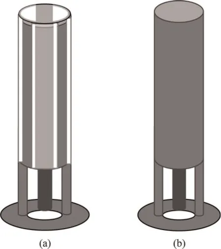
Fig.19. Schematic diagrams of draft tubes:(a) open-sided tube and (b) nonporous tube.
4.2.Desulfurization field

Fig.20. Scheme of the internal devices: (a) draft tube and (b) solid driver.Reproduced from Ref.[109] with permission of Elsevier,copyright 2021.
The large amount of sulfur dioxide produced in the process of burning coal has caused serious harm to the ecosystem and threatens human health[113–115].Owing to their unique structures and properties,the use of spouted beds as desulfurization devices is attracting increasing attention [116].Table 4 summarizes the application progress of different spouted beds in the field of desulfurization in recent years.
In view of the shortcomings of low desulfurization agent utilization rate and desulfurization efficiency,Yuet al.[117] combined the advantages of spray-drying desulfurization and spouted-bed fluidization technology to propose a spray-spouted bed semi-dry fume gas desulfurization technology,and they stud-ied the effect of different operating parameters on desulfurization efficiency.Ca(OH)2was adopted for use in the desulfurizer;when the Ca/S ratio was approximately 1,the desulfurization efficiency reached more than 90%.The desulfurizer exhibited outstanding advantages,such as good fluidization performance and high heat and mass transfer efficiency.It is particularly suitable for the flue-gas desulfurization of small-and medium-sized coal-fired boilers.A new type of double-nozzle rectangular draft-tube spouted bed was applied to a semi-dry flue-gas desulfurization method [118].The desulfurization performance of the device was investigated for different calcium–sulfur molar ratios,static bed heights,superficial gas velocities,and adiabatic saturation temperature differences.The experimental results showed that the desulfurization efficiency was proportional to the molar ratio of calcium and sulfur and the height of the static bed and inversely proportional to the adiabatic saturation temperature difference and apparent gas velocity.Based on the experimental conditions,a correlation formula between the optimal operating range and desulfurization efficiency of the double-nozzle rectangular draft-tube spouted bed was obtained.To improve the desulfurization efficiency,He and Zhang [119] studied the desulfurization efficiency in a new type of spouted bed with a spotting punch draft tube under different operating conditions and compared it with that of a draft-tube spouted bed without a spotting punch.The results showed that the desulfurization efficiency of the spouted bed with a spotting punch draft tube was significantly higher.

Fig.21. Configuration of the contactors used for drying (a) fine sand and (b)ultrafine sand.Reproduced from Ref.[109] with permission of Elsevier,copyright 2021.
To address the issues of particle flow ‘‘dead zone” and insufficient mixing during the desulfurization process,the author’s team proposed spouted beds with LVGs,ISBNs,and IMJSFB;the structures are shown in Figs.22–24,respectively.LVGs are an important means of enhancing mass transfer and heat-transfer technology.They have the advantages of a light shape and simple structure,and they are widely used in electric power,aerospace,and other fields.The principle of action is to generate a secondary vortex in the flowing fluid,change the motion state of the fluid,and reduce the angle between the velocity vector and the heat flow vector to enhance mass transfer and heat transfer under the given working conditions.In the spouted beds with LVGs [120–122],LVGs can effectively increase the particle radial velocity and temperature and enhance the radial mixing of particles and the gas phase between the spout and annulus regions.
A swirling blade nozzle is a secondary enhanced heat-transfer element that has the advantages of obtaining a larger enhanced heat-transfer effect with less resistance,and thus it has become a hotspot in current enhanced heat-transfer research.The intensification principle states that when a fluid flows through a swirling blade,a strong rotational motion is formed as a result of its diversion,and the fluid strongly collides with the wall surface at a certain angle,which promotes heat and momentum transfer between the fluid and the surface of the wall.For a spouted bed with an ISBN[123],the numerical simulation results showed that the swirl blade structure effectively eliminated the dead zone in the cone of the annulus region and significantly improved the comprehensive fluidization degree of the spouted bed.It also promoted the radial velocity and particle temperature of the particles in the bed,which is beneficial for the radial mixing of the particles and gas phase.
The structure of multi-jets can play a significant role in improving the compactness of particles in the annulus region,and their application has recently become a hotspot because they provide reduced energy loss and greater heat-transfer effect.The intensification mechanism is as follows:The gas flowing through the sidejet structure strongly disturbs the particles,which promotes radialmixing between the particles and the gas,and the‘‘dead zone”condition of the particle flow in the cone region is effectively fluidized.The circulation movement of the particles in the annular region is optimized,which is conducive to the full coating of the liquid on the surface of the particles,thereby enhancing the heat and mass transfer between the phases.For the IMJSFB [124],the effect of a multi-jet structure on the gas–solid flow was investigated using a combination of numerical simulations and experiments.Compared with a conventional spouted bed,it was found that the addition of side jets was conducive to the generation of a large number of secondary eddy currents and enhanced the movement of the particles.In addition,the low-density,upper-sparse,axisymmetric side nozzle distribution structure facilitated local fluidization of the inlet gas in the dead zone.
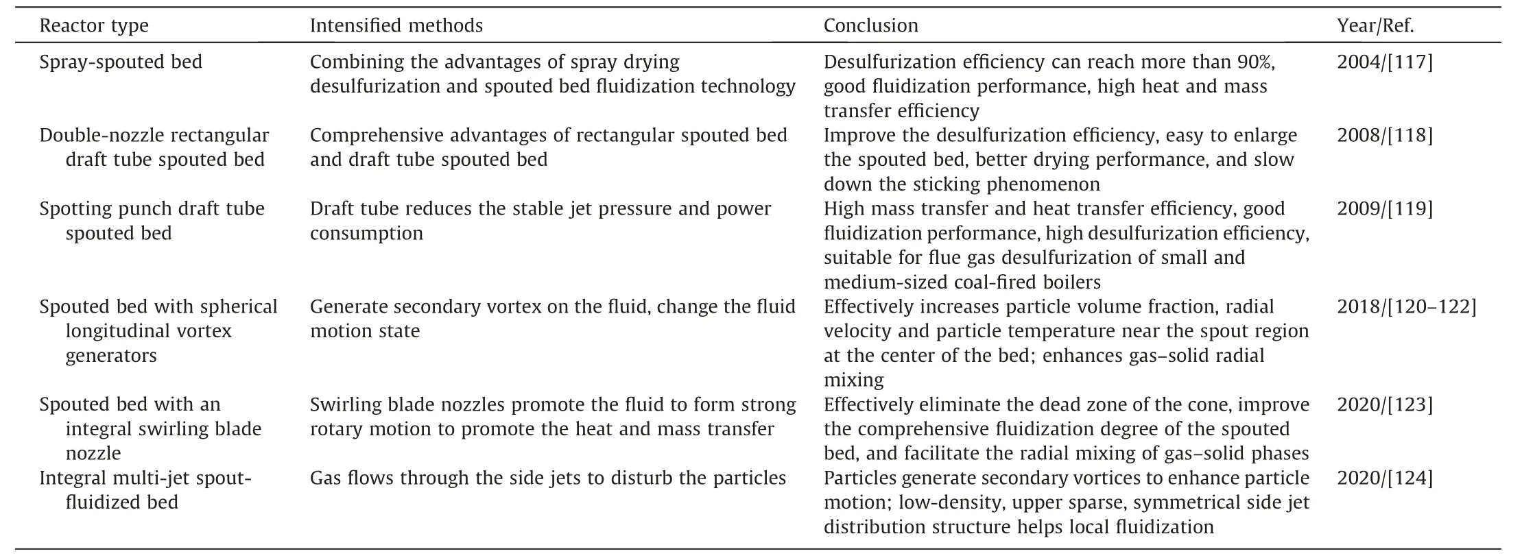
Table4 Application of different spouted beds in desulfurization field

Fig.22. Schematic diagram of spouted bed with LVGs.

Fig.23. Schematic diagram of spouted bed with an ISBN.
Semi-dry flue-gas desulfurization involves a complex multiphase reaction.In this process,water not only provides a reaction site for the reaction but also the water content and temperature have an important influence on the dissolution of sulfur dioxide and calcium hydroxide,thereby affecting the desulfurization efficiency [125].

Fig.24. Schematic diagram of an IMJSFB.
On the basis of spouted beds with LVGs,ISBNs,and IMJSFB[120–124],our team used a ‘‘user-defined function” to define the mass transfer and heat-transfer model through correlation,and we studied the water vaporization process in the desulfurization reaction.It was found that the heights of the fountain in the spouted beds with the above three novel intensification components were significantly lower than that of a conventional spouted bed because the axial kinetic energy was converted into mixing between the particles and the gas in the radial direction,which promoted uniformity of the velocity distribution of the spoutedbed flow field to varying degrees.According to the change curve of the mass fraction of H2O(g) at the outlets of the different spouted beds with time(Fig.25),it was found that different intensification components increased the amount and occurrence of water vaporization.The mass fraction of H2O(g) decreased in the order of spouted bed with ISBN >IMJSFB >spouted bed with LVGs>conventional spouted bed,which is consistent with the distribution trend of the water vaporization rate along the radial direction in the different beds (Fig.26).In addition,it was found that in the simulation range,the gas inlet velocity and gas temperature were 11.2 m∙s-1and 520 K,respectively,which are most favorable for the water vaporization reaction.
It is notable that most of work focused on application of desulfurization in novel spouted beds have been experimental.Since the numerical modeling and tuning parameters can achieve reliable results,more attention should be paid to the numerical simulation and experiment in the desulfurization field.
4.3.Pyrolysis field
Various types of pyrolysis processes have been developed through the control of processing,manufacturing and process conditions of the spouted bed reactor,which has become a key research topic for efficient utilization of resources at domestic and foreign.This section introduces the application research progress of different spouted bed reactors in the field of pyrolysis,listed in Table 5.
Beijing Forestry University has been engaged in research on the rapid pyrolysis of wood since 2004.Researchers have creatively developed spouted circulating fluidized bed rapid pyrolysis equipment[126,127] and conducted related experimental research.The effects of temperature and particle size on the yield of larch fast pyrolysis for bio-oil production were studied using the newly developed spouted circulating fluidized bed rapid pyrolysis equip-ment(Fig.27).It was concluded that the reaction temperature was the most important factor affecting the bio-oil production yield,which reached a maximum at 500–600 K,and the suitable particle-size range of the bed was 0.2–1.2 mm.This study provides a strong basis for the application and promotion of rapid forest biomass pyrolysis technology.For biomass or tire pyrolysis,the liquid yields obtained from the newly developed spouted circulating fluidized bed rapid pyrolysis equipment are higher than those obtained from other fast pyrolysis technologies [11,134–136].In addition,the process was scaled up to 25 kg∙h-1by using a draft tube [137,138].Makibaret al.[128] explored the heat transfer and hydrodynamics of a pilot-plant draft-tube conical spouted bed under various pyrolysis conditions.The effect of temperature on the hydrodynamics of the bed was studied,and the heattransfer coefficients of the wall bed and bed surface were determined.The use of a draft tube can reduce energy consumption and improve system efficiency.The purpose of this study was to better understand the performance of the spouted-bed reactor at pyrolysis temperature for operation under stable conditions,improve the heat exchange rate in the reactor,and minimize the energy demand.Hooshdaranet al.[129] added a draft tube to a conical spouted bed and used CFD to explore the hydrodynamics and heat-transfer parameters under pyrolysis conditions in the bed.They calculated important parameters such as the pressure drop,solid volume fraction,particle velocity,and heat-transfer coefficient between the wall and bed.The results showed that the specularity and particle–wall restitution coefficient had significant effects on the pressure drop and heat-transfer coefficient and that their effect on pressure drop was greater than that on the heat-transfer coefficient.The computational domain used for the simulation is illustrated in Fig.28.Based on the 3D Euler–Lagrange model facilitated by the multiphase particle-cell method,Zhouet al.[130]simulated the gas–solid flow and pyrolysis characteristics of coal in a 500000 t∙a–1industrial-scale spout-fluid bed reactor,with the aim of providing guidance for the industrial application of coal pressurized staged conversion.Fig.29 shows a schematic of the industrial-scale spout-fluid bed pressurized pyrolysis reactor.The reactor contains four main parts: the freeboard area (A),transition area (B),reaction area (C),and distribution area (D).An increase in pressure was found to have a positive effect on the spouting structure and flow uniformity.Increasing the ratio of semi-coking coal was beneficial for coal pyrolysis,but the improvement in the pyrolysis effect was limited.
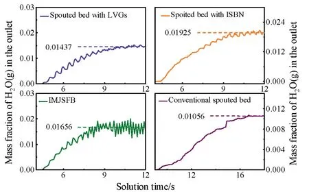
Fig.25. Mass fractions of H2O(g) at the outlet of different spouted beds with time.
In the process of plastic pyrolysis in a reactor,the performance is easily affected by particle agglomeration,which eventually leads to defluidization or bed blockage.The fluidization and bed blockage in a spouted-bed reactor are lower than those in a fluidized bed,and it only occur if the process is carried out under unfavorable operating conditions[139],making the spouted bed an important reactor for plastic pyrolysis [140].To improve the hydrodynamic performance of a conventional spouted bed by alleviating the problem of the elution of fine particles,Altzibaret al.[141]explored the pyrolysis of plastic waste by introducing a fountain restraint and a nonporous draft tube into a conical spouted-bed reactor and determined the stable pyrolysis operating conditions [131].Fig.30 shows a scheme of the spouted bed with the fountain confiner and a nonporous draft tube.The trajectories of the gas and the solid are highlighted in both the entire bed and the surroundings of the draft tube (enlarged zone).The introduction of the device enhanced the gas–solid contact,resulting in a highly stable hydrodynamic state and allowing control of the gas residence time[142].To realize real-time analysis of fast reactions such as biomass pyrolysis,Huet al.designed a micro spouted-bed reactor[132]and comprehensively analyzed the release characteristics of the main pyrolysis gas components,H2,CO,CO2,and CH4.Fig.31 shows a schematic diagram of the micro spouted-bed reaction system,which mainly includes the bottom gas preheating zone,center reaction zone,and top gas outflow zone.With increasing pyrolysis temperature,the reaction time gradually decreased,which proves that the micro spouted bed has unique heat and mass transfer characteristics and low gas backmixing,and thus it is feasible for rapid-reaction characterization.To accurately study the reaction model and kinetic parameters of the spouted bed,Parket al.[133] developed a spouted-bed thermogravimetric analyzer and performed isothermal experiments at 673.15–823.15 K.A schematic of the spouted-bed thermogravimetric analyzer system is shown in Fig.32.This analyzer overcomes the disadvantages of traditional thermogravimetric analyzers owing to the different fluid dynamics.It was found that the contracting volume model better reflected the pyrolysis reaction of sawdust in the spoutedbed reactor,which provides a more reliable result for the prediction of the pyrolysis reaction by CFD.

Table5 Application of different spouted beds in pyrolysis field

Fig.27. Flowchart of a spouted circulating fluidized bed rapid pyrolysis equipment:(1) vibrating circulating feeder,(2) spouting circulating fluidized bed,(3) buffer tank,and (4) filter.

Fig.28. Computational domain used for simulation.Reproduced from Ref.[129]with permission of Elsevier,copyright 2017.

Fig.29. Schematic of the industrial-scale spout-fluid bed pressurized pyrolysis reactor.Reproduced from Ref.[130] with permission of Elsevier,copyright 2019.

Fig.30. Scheme of the spouted bed with fountain confiner and a nonporous draft tube.Reproduced from Ref.[131] with permission of Elsevier,copyright 2021.
Catalyzing the pyrolysis of biomass and coal by adding catalysts is another way to improve the yield and quality of pyrolysis.Using miscanthus as the biomass feedstock,commercial zeolite Socony Mobil-5,and an Al2O3–SiO2matrix from W.R.Grace &Co.as the catalysts,Duet al.[143] proposed a bench-scale conical spoutedbed reactor and concluded that a higher catalyst-to-biomass ratio increased the gas production rate.Elordiet al.[144] carried out the catalytic cracking of high-density polyethylene at 773 K using an HY molecular sieve as a catalyst in a conical spouted-bed reactor.Borsellaet al.[145] used a conical spouted-bed reactor to catalyze the pyrolysis of high-density polyethylene using a laboratory-prepared HZSM-5 catalyst and iron–aluminum–pillared montmorillonite.It was found that the reactor had a high heat and mass transfer rate and excellent performance in handling viscous solid materials,and thus it is a suitable technology for plastic pyrolysis.The analysis of previous publications on the catalytic pyrolysis of spouted beds showed that the current research focuses on the innovation of catalysts and the improvement of pyrolysis methods,whereas there is less innovation of catalytic pyrolysis reactors.Improving catalysts and the pyrolysis method combined with the development of innovative reactors can be the focus of future research to comprehensively improve pyrolysis efficiency.
4.4.Other fields
In addition to being widely used in drying,desulfurization,and pyrolysis,spouted-bed reactors can also be used in coating,biomass and waste gasification,and biomass torrefaction.The follow-ing is a brief overview of the applications of spouted beds in other fields.

Fig.31. Schematic diagram of the micro spouted-bed reaction system.Reproduced from Ref.[132] with permission of Elsevier,copyright 2021.
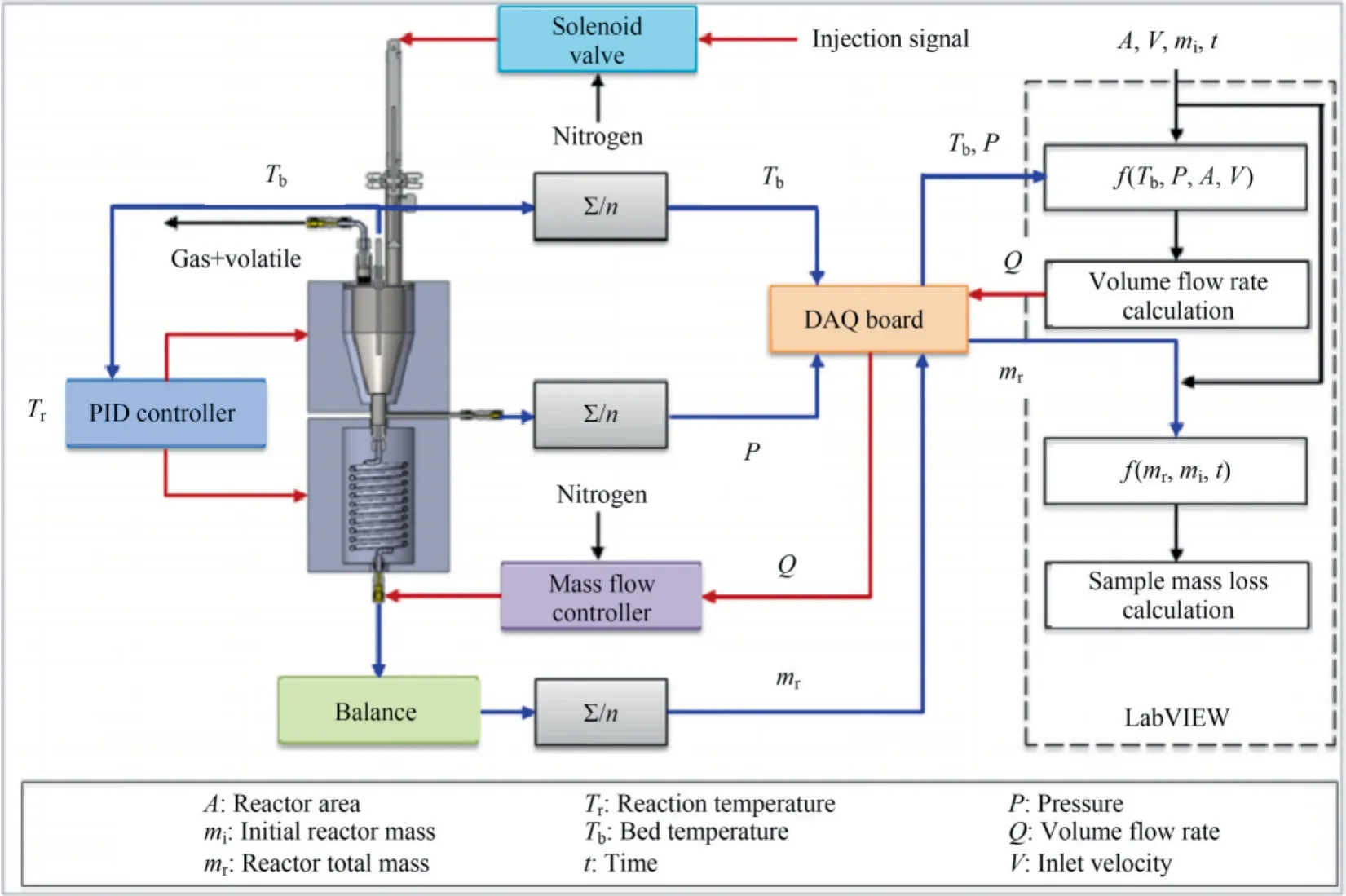
Fig.32. Schematic diagram of the spouted-bed thermogravimetric analyzer system.Reproduced from Ref.[133] with permission of Elsevier,copyright 2022.
In the chemical industry,spouted beds are used in particle coatings because of the less random patterns of particle flow caused by directional gas inlets through slits or tubes.Particle coating is an important industrial process,with many applications in the agricultural,pharmaceutical,chemical,and food sectors [146–148].Its purpose is to evenly coat the particles with a thin layer of coating substance to achieve a minimum coating thickness without cracks,thus maintaining constant product quality during the production process.Through an investigation of the literature,it was found that in the application field of spouted-bed coatings,there are few studies on the modification of bed structure;instead,the studies mainly focus on improving the coating method and increasing the variety of coating particles.Table 6 summarizes the research progress on spouted beds in particle coatings in recent years.

Fig.33. The schematic diagram of bottom cross-sectional view of draft-tube spoutfluid bed.Reproduced from Ref.[151] with permission of Elsevier,copyright 2010.
Torrefaction is a thermochemical transformation process.Torrefaction has received increasing attention as an important preprocessing step for improving the physical properties and chemical composition of biomass.Typically,torrefaction is executed in an inert environment at 473–573 K.However,there is currently less literature on torrefaction reactor design,and researchers are exploring the torrefaction process under different operating conditions and reactor configurations to improve its practical feasibility.The torrification of various biomasses are shown in Table 7.
Coal gasification is a clean coal technology that can be used to produce petrochemical products and substitutes for petroleum fuels;it can also provide clean fuels for coal power generation.In addition,it is widely used for the production of fuel cells and hydrogen[162].The basic process of coal gasification is as follows:Treated dry pulverized coal or a coal–water slurry undergoes a gasification reaction with water vapor and oxygen in a gasifier under specific conditions to generate syngas,which is mainly composed of CO and H2[163].Biomass gasification uses a thermochemical method similar to that used for coal gasification.Coal gasification gasifiers can be divided into moving,fluidized,entrained,and molten bed[164–166].The gasifier used in biomass represents the transformation of a coal gasifier,and the circulating fluidized bed is the most practical type of biomass gasifier.Owing to the differences in characteristics between biomass and coal,direct oxygen blowing is mostly used as the gasification agent in the gasifier to reduce the size requirements of the furnace.The two main types currently being developed are a high-pressure gasifier with direct oxygen blowing,developed by the Gas Technology Institute [167],and an atmospheric-pressure gasifier with indirect ignition,from the Battelle Columbus Laboratory [168].Table 8 summarizes the research progress in biomass,waste,and coal gasification reactors in recent years.

Fig.34. Conical bottom of column.PD: product unload hole,SA: spouting air hole,FC: fluidizing air duct,FN: fluidizing air nozzle.Reproduced from Ref.[153] with permission of Elsevier,copyright 2012.

Fig.35. Different conical bottom mounting openings: (a) general single-nozzle inlet,(b) modified single-nozzle inlet,(c) multi-nozzle inlet,(d) swirl flow design inlet.Reproduced from Ref.[154] with permission of Elsevier,copyright 2014.

Table6 Application of different spouted beds in coating field
5.Conclusions and Future Prospects
Industrial application of intensification technology in spouted beds is of great significance for the future economic viability and meeting the future industrial production demands.This paper systematically summarized its research progress.The following conclusions can be drawn: (a) Spouted bed reactor has excellent heat and mass transfer characteristics,simple structure,lowerpressure drops,occupies an important position in many industrial fields,and has achieved satisfactory results;(b) Driven by the demand of industrial production,the traditional conventional spouted bed has many problems,such as insufficient gas–solid mixing,bed blockage,flow dead zone,and low processing efficiency,etc.,which limit its further application;(c) The development of novel spouted bed technology has become the trend of scientific development,which not only overcomes the limitations of the conventional spouted bed,but also broadens the application range of the spouted bed.It has a wide range of applications in desulfurization,drying,pyrolysis and granulation,etc.,and has great development potential and broad application prospects.

Table7 Application of different spouted beds in torrification field

Table8 Application of different spouted beds in gasification field
Based on this literature review and an understanding of the current research and applications of spouted-bed reactors,the following aspects should also be considered to accelerate the development of spouted beds in the future:
(1) The study of hydrodynamics in a spouted bed is the basis for the quantitative design,optimization,and rational scale-up of various spouted bed reactors.The fluid flow inside the novel spouted bed is complex,and there are many influencing factors;therefore,understanding of its flow law and mechanism needs to be further improved.At this stage,the two-fluid model is primarily used to study fluid flow in a spouted bed.However,the classical two-fluid model is too simplistic for the particle flow in the annulus region,and most predictions are based on empirical correlations,which are different from the actual flow of the particles.Efforts should be made to further optimize improvements to the two-fluid model and to particle-scale simulation methods,such as CFD-DEM.Establishing a new mathematical model that can simultaneously meet the actual situation of a spouted bed and achieve computational efficiency may be a further research focus.
(2) At present,most research on spouted beds is focused on small laboratory equipment’s.It is difficult to increase the size of spouted beds,mainly because the size of the nozzle and material and the diameter of the nozzle and spouted bed have a certain proportional relationship.Further research should focus on solving the problem of large spouted beds to realize the industrial application of novel spouted beds.
(3) Spouted-bed technology can also be used for drying and coating of special materials (such as microencapsulation of micropowder biological products),which can minimize the damage caused by high temperatures to biological products and ensure the efficiency of product embedding.The use of spouted-bed technology for the mass production of micropowder material granulation and coating is an urgent problem to be solved.
(4) The co-gasification of coal and biomass in a spouted bed can inhibit tar production and reduce pollutant emissions,which is the focus of current research.In view of the high temperatures time required and the high experimental cost of cogasification experiments,numerical simulations based on CFD can provide convenient conditions for the design of gasification equipment and processes and the exploration of mechanisms.However,simulation studies of cogasification in spouted beds are at the initial stage of research.This topic will become popular in the energy field in the future.
(5) Spouted beds are outstanding for coating and torrefaction applications,but further work is needed to strengthen the design of spouted-bed reactors to meet the special process requirements.For pyrolysis using spouted beds,improving the catalyst and pyrolysis method,combined with innovation of the reactor,could be the focus of future research to comprehensively improve pyrolysis efficiency.
(6) It is especially critical to combine simulation and experiment of spouted-bed applications in different fields.A good balance between simulation and experiment will be more conducive to the further development of spouted-bed reactors.
Although some achievements have been made in the research on spouted beds and their structural innovation,many aspects remain to be further explored.This review aims to provide references and innovative points for in-depth research on novel spouted-bed technology.
Declaration of Competing Interest
The authors declare that they have no known competing financial interests or personal relationships that could have appeared to influence the work reported in this paper.
Acknowledgements
This work is supported by the National Natural Science Foundation of China (22178286) and Shaanxi Qin Chuangyuan ‘‘scientist and engineer” team construction project (2022KXJ-041).
 Chinese Journal of Chemical Engineering2023年10期
- Chinese Journal of Chemical Engineering的其它文章
- High catalytic performance of CuCe/Ti for CO oxidation and the role of TiO2
- Experimental and numerical studies of Ca(OH)2/CaO dehydration process in a fixed-bed reactor for thermochemical energy storage
- Volumetric and ultrasonic properties of thiamine hydrochloride drug in aqueous solutions of choline-based deep eutectic solvents at different temperatures
- Synthesis of zeolite A and zeolite X from electrolytic manganese residue,its characterization and performance for the removal of Cd2+ from wastewater
- Metal-organic framework-derived Co-C catalyst for the selective hydrogenation of cinnamaldehyde to cinnamic alcohol
- A pseudo transient nonequilibrium method for rigorous simulation of multicomponent separation columns
