
Oxidation mechanism of high-volume fraction SiCp/Al composite under laser irradiationand subsequent machining
2023-11-06 08:05:02HanliangLiuGuolongZhaoZhiwenNianZhipengHuangKaiYangConghuaLiuPengWangandZhenkuanDiao
纳米技术与精密工程 2023年3期
Hanliang Liu, Guolong Zhao, Zhiwen Nian, Zhipeng Huang, Kai Yang, Conghua Liu, Peng Wang, and Zhenkuan Diao
AFFILIATIONS 1 Beijing Spacecrafts,Beijing 100094,People’s Republic of China
2College of Mechanical and Electrical Engineering,Nanjing University of Aeronautics and Astronautics,Nanjing 210016,People’s Republic of China
ABSTRACT Conventional mechanical machining of a composite material comprising an aluminum matrix reinforced with a high volume fraction of SiC particles(hereinafter referred to as an SiCp/Al composite)faces problems such as rapid tool wear,high specifi cutting force,and poor surface integrity.Instead,a promising method for solving these problems is laser-induced oxidation-assisted milling(LOAM):under laser irradiation,the local workpiece material reacts with oxygen,thus forming loose and porous oxides that are easily removed.In the present work,the oxidation mechanism of SiCp/Al irradiated by a nanosecond pulsed laser is studied to better understand the laser-induced oxidation behavior and control the characteristics of the oxides,with laser irradiation experiments performed on a 65%SiCp/Al composite with various laser parameters and auxiliary gases(oxygen,nitrogen,and argon).With increasing laser pulse energy density,both the ablated groove depth and the width of the heat-affected zone increase.When oxygen is used as the auxiliary gas,an oxide layer composed of SiO2 and Al2O3 forms,and CO2 is produced and escapes from the material,thereby forming pores in the oxides.However,when nitrogen or argon is used as the auxiliary gas,a recast layer is produced that is relatively difficul to remove.Under laser irradiation,the sputtered material reacts with oxygen to form oxides on both sides of the ablated groove,and as the laser scanning path advances,the produced oxides accumulate to form an oxide layer.LOAM and conventional milling are compared using the same milling parameters,and LOAM is found to be better for reduced milling force and tool wear and improved machined surface quality.
KEYWORDS SiCp/Al composite,Oxidation mechanism,Nanosecond pulsed laser,Laser-induced oxidation,Heat-affected zone
I.INTRODUCTION
Combining the advantages of the particles and the metal,particle-reinforced metal matrix composites (MMCs) were developed several decades ago and are now used in various areas.1–3Among the most widely used MMCs are those comprising an aluminum matrix reinforced with SiC particles (hereinafter referred to as SiCp/Al composites).They have excellent properties such as high specifi strength and good wear resistance and dimensional stability,which is why SiCp/Al composites are used widely in aerospace,electronics,and other industries.4,5However,their inherent properties of high hardness,high abrasion resistance,and multiinterface characteristics complicate their mechanical machining.
SiCp/Al composites can be machined mechanically using traditional machining processes such as drilling,turning,milling,and grinding,6,7but nontraditional machining processes can also be used,such as electrical discharge machining (EDM),wire cut EDM (WEDM),abrasive water jet machining,and laser-assisted machining (LAM).Xianget al.8researched the mechanisms for tool wear during the drilling of an SiCp/Al composite with 65%particles by volume(hereinafter referred to as a 65%SiCp/Al composite),and their results showed that the best drill was a carbide one coated with diamond via chemical vapor deposition,which has the advantages of stable cutting force,reduced wear,increased number of machined holes,and acceptable machining quality;the main wear mechanisms of the polycrystalline diamond (PCD) tool were abrasive,adhesive,and chemical transformation.Yinet al.9established theoretical and finite-elemen models for the grinding force in single-grain diamond grinding of SiCp/Al composites;they investigated the grinding force,stress distribution,and material removal mechanisms,and the results indicated that the material removal can be divided into four stages: (i) plastic removal of the aluminum matrix,(ii) crack initiation in the SiC particles,(iii) crack propagation in the SiC particles,and (iv) brittle fracture of the SiC particles.
Because of the high hardness of SiC particles,the processing quality obtained by traditional processing methods is relatively poor,with inevitable and serious tool wear,particle breakage,and surface defects.10,11To solve these problems,several nontraditional processing methods have been applied,12–14with one of the most widely used being EDM,which can machine electrically conductive materials regardless of their hardness.15Zhanget al.16used magnetically assisted EDM on a 65% SiCp/Al composite,showing that the pulse current is the main factor influencin the surface integrity.Indeed,magnetically assisted technology can improve the surface integrity significantly Meanwhile,laser machining is a material removal method that involves using high-energy laser beams;it can process materials with high melting point,hardness,and brittleness,and it is characterized by great flexibility17Zhanget al.18used a nanosecond fibe laser to irradiate an SiCp/AA2024 composite and then investigated the laser–material interaction mechanisms;when irradiated by the laser,the SiC particles bulged and the Al alloy matrix was melted and sputtered,and the heataffected zone(HAZ)increased logarithmically with the pulse energy density.
LAM uses a high-energy laser beam to irradiate the local workpiece surface in front of the cutting edge,thereby reducing both the strength and hardness of the material,which is then removed by the cutting tool;consequently,the cutting force is reduced and the tool life is improved.19,20Konget al.21evaluated the tool life and studied the wear mechanisms of both uncoated and coated carbide tools in the LAM of a 45% SiCp/Al composite;the tool life was longer with LAM compared to conventional machining,and the most predominant wear mechanism in LAM was abrasive wear.However,to soften a workpiece material such as an SiCp/Al composite with high hardness and melting point,high laser energy is required,and so the HAZ is relatively large and the machined surface integrity is reduced.Also,the cutting tool must remove the softened material at high temperature,and so its cutting performance is reduced.To solve these problems,Zhaoet al.22,23proposed the hybrid process of laser-induced oxidation-assisted milling(LOAM).During this process,the target area is irradiated by a pulsed laser beam,and the material reacts with oxygen that is supplied simultaneously;this generates a porous oxide layer that is removed quickly by the cutting tool,thereby improving significantl both the machinability of the workpiece material and the tool life.
LOAM is an effective means of reducing the cutting force and prolonging the tool life in the machining of SiCp/Al composites,but its mechanism for material modificatio induced by laser irradiation requires further study.An SiCp/Al composite comprises SiC particles and an aluminum metal matrix,and various laser interactions may occur because of their different optical and thermal properties.The fundamental issue in LOAM is the oxidation mechanism of the SiCp/Al composite under laser irradiation,and understanding that issue would offer better understanding of the oxidation behavior and a method for controlling the laser-induced oxidation process.Herein,we investigate the oxidation mechanism with a 65%SiCp/Al composite as the workpiece material and a nanosecond pulsed laser with a series of pulse energy densities.Laser irradiation experiments were carried out using oxygen,nitrogen,or argon as the auxiliary gas,and the mechanism for forming an oxide layer was analyzed by conducting multiple scans of the composite for each combination of laser parameters.Furthermore,the cutting force and surface quality are compared between LOAM and conventional milling(CONM).
II.EXPERIMENTAL PROCEDURES
A.Workpiece materials
In this study,the workpiece material was a 65%SiCp/Al composite,and its mechanical properties as provided by the supplier are listed in Table I.The average particle size of the SiC particles was 10 μm,and the morphology of the workpiece is shown in Fig.1.The samples were cut into 30×5×5 mm3pieces using WEDM and were then ground using a boron carbide abrasive.Moreover,to remove any impurities,the samples were cleaned ultrasonically in acetone for 15 min.
B.Experimental setup
A nanosecond pulsed laser with a wavelength of 1064 nm and a pulse durationτof 100 ns was used in this experiment,as shown in Fig.2.The maximum average powerPmaxwas 20 W,the pulse frequencyfwas 20 kHz,the diameterDof the focused facula was 50 μm,and the focal length of theF-θ lens was 210 mm.The main factor is the average laser power,which ranged from 4 to 12 W in intervals of 2 W.The pulse energy densityFand light intensityIwere calculated as

TABLE I.Mechanical and physical properties of 65% SiCp/Al composite used in present study.
and in this experiment we hadF=7.84–23.51 J/cm2andI=7.84×107to 2.35×10⁸W/cm2.The pulse energy density plays a central role in the laser-induced oxidation process.
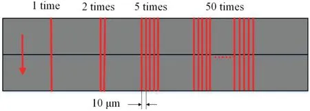
FIG.3.Schematic of laser scanning paths.

FIG.4.Morphology of polycrystalline diamond(PCD)milling tool.
To analyze the reaction mechanism between the laser and the material in different gas environments,we used oxygen,nitrogen,or argon as the auxiliary gas with the same laser parameters.To analyze the formation process of an oxide layer under laser irradiation,we performed once,twice,and fiv and 50 times for each auxiliary gas and set of laser parameters.The scanning speedvwas 1 mm/s,and the track displacement between adjacent scanning lines was 10 μm.The laser scanning paths are shown schematically in Fig.3.
A vertical milling center was used in the milling experiment,and the milling tool was a straight-tooth PCD one with acemented carbide shank brazed with PCD plates.The morphology of the PCD milling tool is shown in Fig.4,and its parameters are listed in Table II.The LOAM parameters were a spindle speed ofn=10 000 rpm,a feed rate per tooth offz=7.5 μm/z,and a depth of cut ofap=0.1 mm.For comparison,CONM was also carried out using the same parameters and material removal.
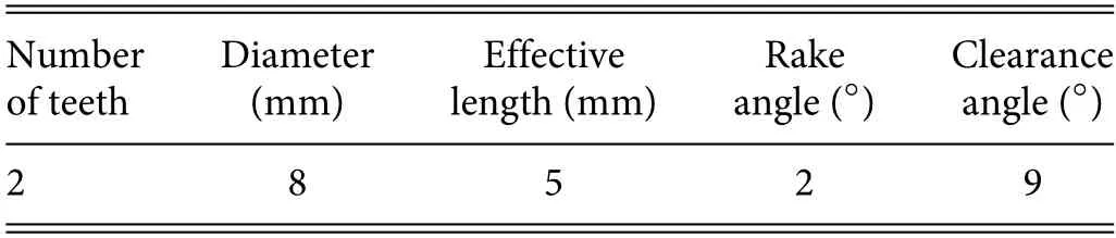
TABLE II.Geometrical parameters of PCD milling tool.
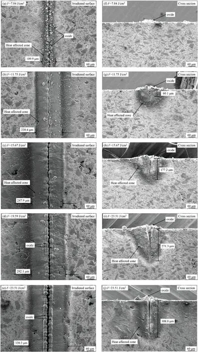
FIG.5.Surface and cross-sectional morphologies of material obtained after a single scan in oxygen with various laser energy densities.
C.Characterization
A scanning electron microscope (SEM) (S8220;Hitachi) was used to observe the working material,the laser-treated surface,and the HAZ.The elemental compositions were measured using energydispersive spectroscopy (EDS),and the products were detected using x-ray diffraction (XRD).The machined surface morphology was observed using another SEM(S4800;Hitachi),and the surface roughness was obtained using an M1 perthometer;the workpiece was measured three times in different areas of the machined surface to obtain the arithmetic mean roughness.The measurement process complies with the national standard GB1031-83.The milling forces were measured using a dynamometer(9256C1;Kistler)with a maximum sampling frequency of 30 kHz and a threshold force of 0.002 N.
III.RESULTS AND DISCUSSION
A.Effects of pulse energy density on ablation depth and HAZ
The pulse energy densityFis the main factor affecting the interaction between the pulsed laser and the material.To analyze the effects of the laser energy density on the 65%SiCp/Al composite,we usedF=7.84,11.75,15.67,19.59,and 23.51 J/cm2.The surface morphologies of the material obtained after a single oxygen-assisted scan are shown Fig.5;Figs.5(a)–5(e)show SEM images of the irradiated surface under different pulse energy densities,and Figs.5(f)–5(j)show the corresponding cross-sectional morphologies.
From Figs.5(a)–5(e),both the processing area and the HAZ on the surface increase with increasing laser energy density,and from Figs.5(f)–5(j),so does the laser processing depth.ForF=7.84 J/cm2[Fig.5(a)],a small groove appears on the surface of the material and follows the laser scanning path,with white fin granular oxide distributed on both sides of the groove;the groove is very shallow and there is almost no HAZ [Fig.5(f)],and tiny oxide deposits on the scanning area protrude from the surface.ForF=11.75 J/cm2[Fig.5(b)],the width of the HAZ on the machined surface increases to 220.4 μm,and the oxide becomes denser and accumulates on both sides of the groove;the groove depth on the corresponding cross section increases to 60.1 μm,and the HAZ is more obvious [Fig.5(g)].ForF=19.59 J/cm2[Fig.5(d)],the HAZ width is 282.1 μm,and the oxide on both sides of the groove increases in volume and becomes denser;the groove depth increases to 271.3 μm[Fig.5(i)].ForF=23.51 J/cm2,the HAZ width is 320.2 μm[Fig.5(e)]and the groove depth is 308.8 μm[Fig.5(j)].Therefore,with increasing laser energy density,both the HAZ width and groove depth increase,as does the amount of oxide deposited on both sides of the groove.
Figure 6 shows more intuitively how the HAZ width and groove depth change with the laser energy density,and also included are the data obtained with nitrogen and argon for the same energy densities.From Fig.6(a),with increasingF,the HAZ width increases with the assistance of oxygen,nitrogen,or argon,and the observed growth trends are similar.The HAZ width increases rapidly at lowerFbut slower at higherF,suggesting that it approaches a fixe value for sufficientl highF;we attribute this to the limitation of the spot diameter.Furthermore,under the same energy density,the HAZ widths obtained with the different auxiliary gases are similar,albeit that that obtained in an oxygen environment is slightly higher because oxygen is more active than nitrogen or argon and so reacts more easily with the high-temperature material after laser irradiation.From Fig.6(b),the depth of the groove obtained by laser irradiation also increases with increasingF.The rate of increase of the groove depth is larger than that of the HAZ width,and the groove depths obtained with the same laser energy density but different auxiliary gases are very similar.
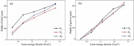
FIG.6.(a)Width of heat-affected zone(HAZ)and(b)depth of groove obtained with various laser energy densities.
Therefore,the laser energy density influence significantl both the width of the HAZ on the material surface and the depth of the groove.With increasing laser energy density,the energy absorbed by the material increases,and this intensifie the reaction of the workpiece material,thereby increasing both the HAZ width and the groove depth.Using oxygen as the auxiliary gas promotes the HAZ on the material surface,but for the same laser energy density,the choice of auxiliary gas has little effect on the machining groove depth.
B.Effects of auxiliary gas on oxidation behavior
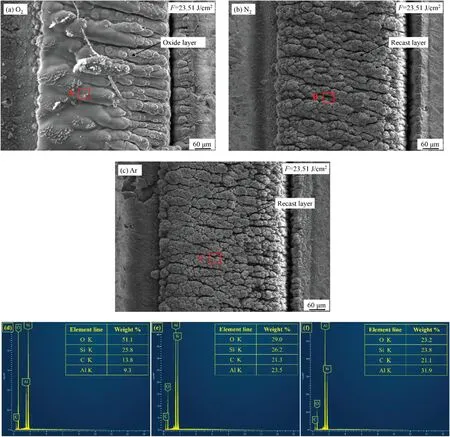
FIG.7.SEM images of laser-irradiated surfaces obtained in(a)O2,(b)N2,and(c)Ar,and EDS spectra of material surfaces irradiated in(d)O2,(e)N2,and(f)Ar.
The quality of the oxide layer generated in an oxygen environment is better than that in an atmospheric environment,and the oxide layer is denser and easier to remove under the same laser parameters.To investigate further how the gas environment influence the formation of an oxide layer in the laser-induced oxidation process,we selected oxygen,nitrogen,or argon as the auxiliary gas,and we subjected the machined surface to EDS and XRD to analyze the products in the different gas environments.
Figure 7 shows SEM images of the machined surface for a scanning speed of 1 mm/s,a pulse energy density of 23.51 J/cm2,a track displacement of 10 μm,and laser scanning performed 50 times.Figure 7(a)shows the morphology of an oxide layer obtained in oxygen.A white porous oxide layer forms in the laser scanning area,being very loose and easily removed by ultrasonic cleaning.The surface of the oxide layer is wavy and undulating and contains some white flocs these are oxides generated from the oxide layer under the blowing of the oxygen flow which adhere to the oxide layer surface.According to the cross section in Fig.8(a),the oxide layer has a relatively large volume,and it protrudes to a certain height from the surface of the material at this pulse energy density.On the other hand,there are many holes in the lower part of the oxide layer,and the part near the material is irregularly shaped;this part comprises the bottom of the groove and the resolidifie material.Figure 7(b)shows the morphology of a recast layer obtained in nitrogen.Its surface is rough,irregular,and composed of many fin particles and clusters with dense gaps between them.The recast layer is black in color and difficul to remove.Figure 8(b) shows the recast layer in cross section,again protruding from the material surface.However,the volume of the recast layer is less than that of the oxide layer,even though the former contains many folds and crevices that increase its volume.The bottom morphology of the recast layer is similar to that of the oxidation layer,and this can be attributed to the gas being unable to penetrate the material far from the workpiece surface.Figures 7(c)and 8(c)show the morphology and cross section,respectively,of the recast layer obtained in argon.The surface morphology of this recast layer is similar to that obtained in nitrogen and is a typical morphology for laser reaction with a material in an inert gas.
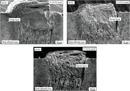
FIG.8.SEM images of cross sections obtained in(a)O2,(b)N2,and(c)Ar.
From comparing the morphologies obtained in the three auxiliary gases,oxygen is best for promoting the formation of the oxide layer.In an inert gas,there is almost no reaction between the gas and the material,and under laser irradiation,the material removed by sputtering solidifie again to form a recast layer with high hardness and irregular morphology and that is very rough and difficul to remove;consequently,this has adverse effects on cutting.However,in oxygen,the molten material that would otherwise have formed a recast layer instead reacts with the oxygen to form a loose oxide layer.This happens because oxygen reacts relatively easily with the material,and compared with the recast layer,the oxide layer is larger and easier to remove,which is conducive to further machining.

FIG.9.XRD spectra of material surfaces irradiated in(a)O2,(b)N2,and(c)Ar.

FIG.10.SEM images of material surfaces scanned various times.
The EDS results for the surface of the workpiece irradiated in oxygen,nitrogen,and argon are shown in Figs.7(d)–7(e),respectively,for the sampling areas marked by red boxes A,B,and C in Figs.7(a)–7(c),respectively.In Fig.7(d),the oxygen content is the highest(51.1%)and the aluminum content is the lowest(9.3%).The oxide layer consists mainly of SiO2and Al2O3.The vaporization point of aluminum (2740 K) is lower than that of silicon carbide(3103 K),so when the temperature rises under laser irradiation,aluminum is more likely to vaporize and escape into the air,even if it reacts with oxygen to form Al2O3.It is also blown away by the airflow making it difficul for it to accumulate on the workpiece surface.Silicon carbide has a higher vaporization temperature and mainly forms molten matter at high temperatures.Moreover,it forms SiO2with oxygen,which accumulates easily in the oxide layer.Therefore,the Si content is increased and the Al content is decreased within the oxide layer.As shown in Figs.7(e) and 7(f),the results of EDS analysis under nitrogen and argon are similar,i.e.,lower oxygen content and higher carbon and aluminum contents.The main components of the recast layer are resolidifie silicon carbide and aluminum;the carbon in silicon carbide does not react with nitrogen or argon,which is why the carbon content is increased,but because aluminum is active,that on the surface of the recast layer reacts with oxygen in the atmosphere after laser irradiation to form Al2O3,which is why less oxygen is detected.
Figure 9 shows the XRD patterns obtained in the different gas environments.Figure 9(a) shows that when oxygen is used as the auxiliary gas,the products in the irradiation area are mainly SiC,Al,Al2O3,and SiO2.Figure 9(b) shows that in nitrogen,the main products in the irradiation area are SiC,Al,Si,and AlN,with the SiC and Al being from the reinforcing particles and the matrix material,respectively,and resolidifying on the surface.A small amount of Si is produced by the decomposition of SiC particles at high temperature(≥2600°C),as shown in Eq.(3),and AlN is formed by the reaction of Al and N2in the laser high-temperature environment,as shown in Eq.(4):In Fig.9(c),the main products in argon are SiC,Al,and a small amount of Si.

FIG.11.SEM images of material cross sections scanned for various times.
C.Oxidation mechanism of SiCp/Al composite under laser irradiation
To analyze further the reaction mechanism and the formation process of an oxide layer under laser irradiation,oxygen was used as the auxiliary gas during the irradiation experiment with a laser energy density of 23.51 J/cm2.The scans were performed once,twice,and fiv and 50 times,and the scanning interval was 10 μm.SEM images of the irradiated surface with different scanning times are shown in Fig.10,and SEM images of the cross section are shown in Fig.11.
As shown in Fig.10(a),under laser irradiation,a groove is formed in the central area of the scanning path,with convex oxide deposits distributed on both sides of the groove.In Fig.10(b),when scanning the second path,the laser beam moves 10 μm to the right with respect to the position of the firs scan.There is still a groove on the surface,which is located in the center of the second scan path,but the groove formed in the firs scan is fille and covered by the oxide.The HAZ width is 174 μm on the left side and 150 μm on the right side.As shown in Fig.10(c),after scanning fiv times,there is only one groove on the surface,which is distributed in the center of the fift scanning path;the grooves generated in the firs four scans are covered by the oxide.The HAZ width on the left side of the groove is enlarged to 213 μm,and that on the right side is 140 μm.The oxide accumulation area on the left side also widens gradually.After 50 scans,the groove is located in the center of the 50th scan path,as shown in Fig.10(d),and the oxide layer accumulated on the left side forms a porous oxide layer.

FIG.12.Schematics of oxidation mechanism of SiCp/Al composite under nanosecond pulsed laser irradiation.
Figure 11 (a)shows a SEM image of the cross section obtained after one scan;the groove generated by laser irradiation penetrates the material,with little protruding oxide on either side.Figure 11(b)shows the cross section after two scans;compared with Fig.11(a),the groove is now slightly wider with more oxide on its left side.Figure 11(c) shows the cross section after fiv scans;the groove is now even wider with even more oxide on its left side.Figure 11(d)shows the cross section after 50 scans;a loose oxide layer was produced in the scanning area,and the groove formed during the fina scanning remains on the far right.In summary,the oxidation products generated by each scan fil the groove generated by the previous one,and the oxides accumulate gradually to form the oxide layer;this is shown also by the texture trend of the end face of the oxide layer,which is growing to the left.
The formation mechanism of an oxide layer under laser irradiation is shown schematically in Fig.12.As shown in Fig.12(a),under laser irradiation,the material absorbs the laser energy in a very short time,and a large temperature rise is produced rapidly in a small volume because of the high energy of the pulsed laser.At high temperatures,aluminum and silicon carbide melt and vaporize,and because of the lower vaporization point of aluminum(2740 K)compared to that of silicon carbide (3103 K),aluminum vapor is generated more easily,so the gas-phase material is mainly aluminum vapor with a small amount of silicon carbide vapor.As shown in Fig.12(b),as the volume of this material increases after vaporization,it diffuses to the outside and carries molten liquid aluminum and silicon carbide.As shown in Fig.12(c),small amounts of molten aluminum and ejected silicon carbide react with oxygen to form SiO2,Al2O3,and CO2,and the reaction equations are24,25
As shown in Fig.12(d),the generated oxidation products(SiO2and Al2O3)are deposited and stacked on both sides of the grooves,with CO2released into the air.Figures 12(e)–12(h)show the second laser scanning process,whose reaction process is the same as that of the firs one.The difference now is that the oxide generated by the second laser irradiation accumulates in the groove generated by the firs one.Figure 12(i)shows a schematic of the situation after multiple scanning,where the oxide accumulates gradually in the groove until a loose oxide layer is formed.
D.Cutting force and surface quality
To verify the feasibility of LOAM,experiments were performed in which the 65% SiCp/Al composite was machined using both LOAM and CONM.The milling parameters used in both processes were a spindle speed ofn=10 000 rpm,a feed rate per tooth offz=7.5 μm/z,and a cut depth ofap=0.1 mm.
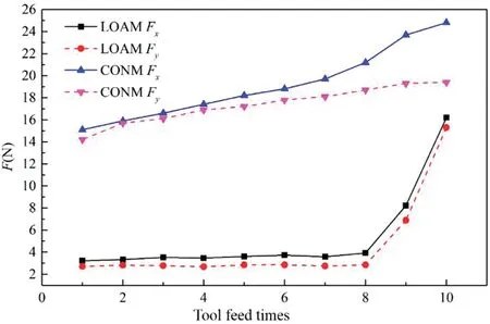
FIG.13.Variation of milling force under different processes.

FIG.14.SEM images of surfaces machined with different processes.
Figure 13 shows how the milling force measured for each machining process varied,where the machining length of each tool feed was 50 mm.For LOAM,in the firs eight tool feeds,the milling tool mainly cut off the loose oxide layer,and the ninth and tenth tool feeds mainly removed the residual oxide layer,transition layer,and some matrix materials to avoid the influenc of the HAZ.For CONM,the milling force componentsFxandFywere 15.1 and 14.2 N,respectively,for the firs tool feed,and with more tool feeds,the tool wear increased gradually,as didFxandFy;at the tenth tool feed,FxandFyreached 24.8 and 19.4 N,respectively.For LOAM,FxandFywere 3.2 and 2.7 N,respectively,in the firs tool feed.Because the loose oxide layer was always removed during the firs eight tool feeds and the tool was almost free of wear,there was no significan change in milling force.In the eighth tool feed,FxandFywere 3.9 and 2.8 N,respectively.Because of the loose combination between oxides,it was easy to remove the oxide layer and produce powdery chips.Thus,the milling force was very small.The ninth tool feed removed the transition layer and some base materials,andFxandFyincreased to 8.2 and 7.4 N,respectively.The transition layer contains residual oxide,the recast layer,and heat-affected material,which is easier to remove than workpiece material.Thus,the cutting force when removing the transition layer was less than that of CONM using the same cutting parameters.The tenth tool feed mainly removed the matrix material to avoid the influenc of the HAZ.At this time,FxandFywere 16.2 and 15.3 N,respectively.Only slight tool wear occurred when removing the transition layer,and therefore the milling force was similar to that in the initial processing stage in CONM.By using LOAM,the cutting force can be reduced greatly and the tool life can be improved greatly.
Figures 14(a)and 14(b)show SEM images of the machined surface obtained by LOAM and CONM,respectively,with the same selective magnification The surface roughnessRawas measured to be 0.131 and 0.265 μm,respectively.According to Fig.14(a),the surface obtained by LOAM was very fla with few machined surface defects.As can be seen,there were only a few pits with small size and depth,which can meet the application requirements of high-volume-fraction SiCp/Al composites.According to Fig.14(b),the surface obtained by CONM had more defects.Compared with LOAM,CONM produced significantl more pits in the same area,and their average size was much larger than that under LOAM.In addition,the trace of the cutting path is more obvious.In the LOAM experiment,the oxide layer was loose and porous,so the milling force when removing it was very small.Consequently,the tool was hardly worn and remained sharp,so the compression was small when removing silicon carbide particles.Thus,the number and average size of pits generated on the machined surface were reduced.Because of the sharp tool nose and cutting edge,the cutting load was small and the cutting process was stable,so the cutting path was not obvious.Therefore,the surface quality obtained by LOAM is better than that by CONM.
Based on the above analysis,LOAM is effective in reducing machined surface defects and improving the quality of the machined surface.This is because the tool in LOAM is removing the loose oxide layer most of the time,so the tool wear is very small,and the tool remains sharp in the fina finishin stage.
IV.CONCLUSIONS
In this paper,the oxide-layer formation laws and mechanism for a 65%SiCp/Al composite under nanosecond pulsed laser irradiation were studied in detail,and LOAM and CONM were compared using the same milling parameters.We draw the following main conclusions.
With increasing laser energy density,both the ablated groove depth and HAZ width increase,but there is no influenc on the groove depth with different gas assistance.Every time the laser scans the material area,the sputtered molten material reacts with oxygen to form oxides,and the accumulated oxides gradually form an oxide layer with more scans.
An oxygen environment promotes the formation of an oxide layer.In an oxygen environment,a loose oxide layer forms that is relatively easy to remove.
Compared with CONM,LOAM is better for reduced milling force and tool wear.Furthermore,machining damage is contained and higher surface quality is achieved with the LOAM.
ACKNOWLEDGMENTS
This work was supported by the Fundamental Research Funds for the Central Universities(Grant No.NT2021020).
AUTHOR DECLARATIONS
Conflict of Interest
The authors have no conflict to disclose.
DATA AVAILABILITY
The data that support the finding of this study are available from the corresponding author upon reasonable request.
- 纳米技术与精密工程的其它文章
- Status of research on non-conventionaltechnology assisted single-point diamond turning
- Research trends in methods for controlling macro-micro motion platforms
- Droplet microfluidic chip for precise monitoring of dynamic solution changes
- Characteristics of the pressure profile in the accelerator on the RF negative ion source at ASIPP
- An optical tweezer-based microdroplet imaging technology
- Effects of laser energy on the surface quality and properties of electrodeposited zinc-nickel-molybdenum coatings