An optical tweezer-based microdroplet imaging technology
Cong Zhai,Yujian Hong,Zuzeng Lin,Yulu Chen,Han Wang,Tong Guo,and Chunguang Hu
AFFILIATIONS State Key Laboratory of Precision Measuring Technology and Instruments,Tianjin University,Tianjin 300072,China
ABSTRACT Microspheres can break the diffraction limit and magnify nano-structure imaging,and with its advantages of low cost and label-free operation,microsphere-assisted imaging has become an irreplaceable tool in the life sciences and for precision measurements.However,the tiny size and limited imaging fiel of traditional solid microspheres cause difficultie when imaging large sample areas.Alternatively,droplets have similar properties to those of microspheres,with large surface curvature and refractive-index difference from the surrounding environment,and they can also serve as lenses to focus light for observation and imaging.Previous work has shown that droplets with controllable size can be generated using an optical tweezer system and can be driven by optical traps to move precisely like solid microspheres.Here,a novel microdroplet-assisted imaging technology based on optical tweezers is proposed that better integrates the generation,manipulation,and utilization of droplets.
KEYWORDS Optical tweezers,Photogenerated droplets,Assisted imaging,Controllable generation
I.INTRODUCTION
Microsphere nanoscopy emerged in 2011,and as a simple technology,microsphere imaging is still based on optical principles that allow direct magnificatio and imaging of nanostructures at scales below the diffraction limit using a conventional optical microscope.1,2With intensive research,several teams have developed various microsphere-based methods for optical superresolution.By simply placing the transparent microspheres on the surface of the sample,the minimum resolution of the microscope can reach 50 nm.3To overcome their tiny fiel of view(FOV)and inconvenient maneuverability,the microspheres can scan a large area of the sample via the high-precision manipulation capability of an atomic force microscope (AFM)4,5or an optical tweezer(OT) system,6,7thus enabling imaging of a larger area of the sample.However,these approaches still require the scanning and stitching of microsphere images,and influence by spherical distortion,microsphere imaging shows obvious distortion and brightness unevenness,which makes image stitching significantl more difficult8
In previous studies,we have shown a precisely controllable way to generate photogenerated droplets in a specifi mixed solution by using an OT system.9The generated droplets have a higher refractive index than the surrounding solution and thus achieve similar properties to those of microspheres.10Consequently,the droplets can also be manipulated by optical traps to move randomly.11,12Through further research,we found that the essence of droplet generation is the action of laser traps in multiple physical fields13the“trapping”process dominated by gradient forces and the “convergence” process caused by photothermal and thermal acceleration effects.14,15This indicates that droplet photogeneration can occur in not only a mixture of isopropyl alcohol(IPA)and phosphate-buffered saline but also other solutions with similar properties.Also,the generated droplets have ideal light transmission and can gather light as can solid microspheres but while being softer and more plastic,and they will not scratch the sample surface,similar to a cell biomagnifier16
Indeed,some researchers have already used OTs to manipulate lipid droplets in order to detect the fluorescenc signals of other structures in the whole cellular environment,17leading to the expectation that liquid droplets can give rise to harmless and compatible observation technology with nanoscale spatial resolution.However,because lipid droplets can only be used in biological environments and it is difficul to change their size,thereby preventing taking advantage of the mutual solubility of droplets,herein we use an OT system to generate controlled droplets efficientl and liberally in a mixture of water,IPA,and silicone oil (40 cs,watersoluble),and we use them to assist in the magnificatio of samples.In this way,we integrate droplet generation,transport,and utilization in the OT system,offering a preliminary verificatio of the feasibility of microdroplet-assisted imaging.Furthermore,photogeneration makes the preparation and use of droplets more convenient,being simpler and faster than the cantilever structure and other non-contact microsphere imaging solutions.With excellent controllability and wide versatility,this method has great potential for applications such as harmless detection and nanostructure measurement.
II.EXPERIMENTAL WORK
A conventional transmission-based OT system uses objective and condenser lenses opposed along the axis,which requires highprecision focal alignment of the illumination with the optical trap.Consequently,the overall thickness of the sample chamber is limited by the short working distances of the objective and condenser lenses,and the observed sample and the sample chamber must have high transmittance to ensure sufficien illumination for imaging.Therefore,in the present work,a reflectiv OT system using only one objective lens is chosen to observe non-transparent samples and to achieve a simplifie system structure as shown schematically in Fig.1.
To produce a stable and reliable optical trap and obtain a clear resolution,the chosen laser is a single-frequency linearly polarized ytterbium fibe laser from IPG Photonics (YLR-5-LP,1064 nm,5 W),and the objective lens is a high numerical aperture(NA)objective (ZEISS,NA:1.2,63×).The main video camera (Manta G-507,monochrome) is mounted on a linear guide to separate the imaging of the sample from the optical trap.Kohler illumination is used to generate a bright and extremely even illumination of the sample chamber to avoid interferences such as lamp filamen and shadows,in the resulting image.Besides,several 450-nm bandpass filter are used to prevent chromatic dispersion resulting in reduced imaging quality.
For stable droplet generation,a custom microfluidi chip and an air pressure-driven injection system are used.The custom microfluidi chip uses a metal substrate and is capped with a cover slip and UV-curable adhesive to ensure maximum light transmission for the optical trap manipulation and the sample observation.18The height of the microfluidi channel can be adjusted in the range of 200–1000 μm,ensuring the ability to load samples with different thicknesses.The air pressure can be adjusted with an accuracy of 400 Pa,and the injection rate of droplet samples can be controlled between 10 μL/min and 500 mL/min under constant air pressure.Because of the high concentration of the original silicone oil,it must be diluted with pure water to disperse into nano-droplets in IPA and distribute evenly.Therefore,the original solution is mixed with silicone oil,water,and IPA at a volume ratio of 1:5:10.See the supplementary material for the detailed photogeneration process and the droplet characteristics.
Because droplet photogeneration involves the aggregation and fusion of nano-scale droplets,the generated droplets have a higher refractive index than the surrounding solution.19This also means that the OT system can manipulate the droplets to achieve precise displacement,as with conventional microspheres.In addition,with the ideal light transmission and refractive-index differences,droplets can also concentrate light and magnify the sample for imaging.Compared with solid microspheres,the size of droplets can be adjusted by changing the optical trap power,droplet generation time,or original solution concentration during the generation process.This means that it is possible to change the FOV,depth of fiel (DOF),contrast,or other imaging characteristics by generating droplets with different ingredients or shapes.20,21
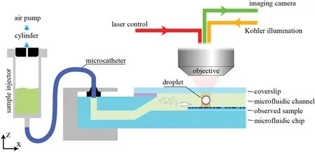
FIG.1.Optical tweezer(OT)-based microdroplet generation scheme.The sample chamber is supported by a displacement stage and can be moved relative to the objective at micrometer scale.
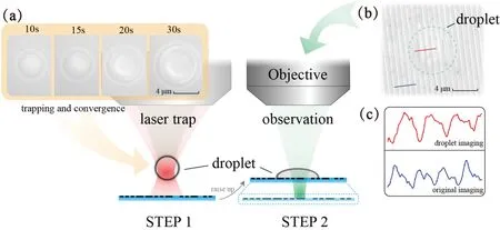
FIG.2.Droplet-assisted imaging process based on OT system:(a)efficient droplet generation;(b)imaging of droplet after adhering to sample surface;(c)comparison of gray values of micro-stripe imaging in(b)before(blue)and after(red)using the droplet,showing the original stripe width and that enlarged by the microdroplet,respectively.
For instance,Fig.2 shows a typical droplet generation process.In step 1,the laser is turned on and the optical trap is placed above the sample surface.The injector is driven by the air pressure,and the injection rate is 200 μl/min.Within half a minute,the droplet diameter grows to greater than 5 μm under the optical trap,which is sufficien to replace solid microspheres for assisted imaging.Then in step 2,the height of the sample chamber is raised slightly so the droplet can be brought closer to the sample with nanostructures.The focusing surface of the camera is adjusted at the same time to allow precise focusing of the droplet image.Benefitin from the affinit of liquids to solids,the droplet is attached stably to the sample surface,but the contact surface with the surrounding solution still maintains a certain curvature under tension,determined by the properties of the original solution.22Besides,the imaging FOV and DOF are also influence by the droplet size and its surface curvature after attachment.23,24See the supplementary material for a comparison of the imaging characteristics with solid microspheres.
In addition,liquid droplets can penetrate and fil tiny pits on the sample surface to a certain extent,obtaining stronger light reflectio of the sample and effectively improving the imaging quality of the camera.Compared with solid microspheres,the generated droplets can prevent scratches on the sample surface and are easily cleaned off with pure water,making it possible to observe samples without damage or contamination.
III.THEORY AND DISCUSSION
It has been demonstrated that microspheres can be treated as micro-lenses and can be used to identify details of objects with sizes below the conventional diffraction limit.25If microspheres are half immersed in solution,then the difference in the refractive index also leads to the convergence of light and thus magnifie the sample.26Geometrically,a droplet adhering to a sample surface is propped up under the action of liquid tension,similar to a semi-submerged microsphere or a plano-convex solid immersion lens,27–29and as described previously,with the high curvature of the contact surface and the refractive-index difference with the surrounding solution,the droplet can refract light like a microsphere with amplificatio ability.26This indicates that the research methods used for solid microspheres are also applicable to the imaging properties of liquid droplets.
However,because of its tiny size and all-liquid environment,the thickness of the droplet after adhering to the sample surface is unknown and cannot be measured directly.However,given that(i)the droplet volume does not change during adhesion and(ii)only its shape changes under the balance of tension and sample affinity the droplet thickness can be inferred from the droplet diameters as seen from the imaging camera before and after adhering to the sample surface.30
The droplet shapes before and after adhering to the sample are shown in Fig.3.Under surface tension,the generated droplet forms a sphere in the surrounding solution,31and its volumeViswhereRis the radius of the sphere.After attaching to the sample,the droplet shape changes to a spherical cap,but the volume does not change.At this point,we have
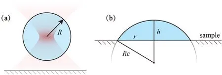
FIG.3.Changes in droplet geometry:(a)schematic at time of droplet generation;(b)dimensions after droplet adheres to sample.
whereRcandhare the radius and height of the spherical cap,respectively.Geometrically,we have
and the height of the spherical cap is
whereris the radius of the contact surface of the droplet with the sample.For example,the droplet in Fig.2(a)has a size of 5 μm after the generation process and grows to 6.4 μm in diameter after attaching to the sample surface,at which point the droplet thickness is deduced as being 3.1 μm.
Based on these parameters,we simulated the focusing characteristics of the droplet in the COMSOL Multiphysics software.With irradiance being the main factor affecting the imaging of a microscale lens,32we began by using wave optics simulation to fin the focal point of the micro-droplet;in this simulation,the refractive indices of the silicone oil and surrounding solution were set to 1.5 and 1.3,respectively,and the results are shown in Fig.4(a).The maximum light intensity is at 15 μm along the light propagation axis,which corresponds to 12.45 μm from the optical center.Because the surface curvature of the droplet after attachment is not as large as that of a microsphere,there is no need to consider the change in reflectivit of the light when it passes through the droplet,so this point of maximum intensity can be regarded as being the optical imaging focus of the droplet.33
Figure 4(b) shows the simplifie imaging model,whereu(=1.55 μm)is the distance between the droplet’s optical center and the sample surface,andvis the distance between the droplet’s magnifie virtual imaging plane and the optical center,which is currently unknown.However,if the droplet is be considered as a micro-lens,then its imaging position satisfie
wherefis the distance between the optical center and the focal point identifie from the simulation.Finally,the virtual image of the droplet can be determined to be 1.77 μm from the optical center,and the magnificatio is presumed to be 1.14×.
IV.RESULTS
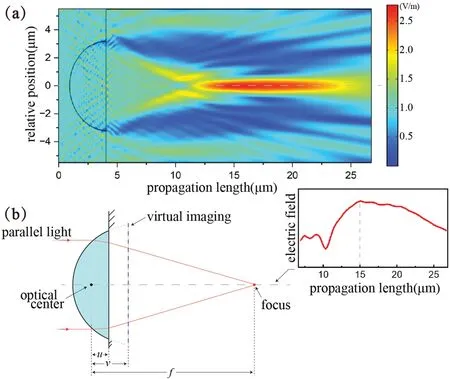
FIG.4.Simulation and imaging analysis of attached droplet: (a) simulation results for a single droplet and its simplified imaging model;(b) simplified imaging model of attached droplet,with the red curve showing the distribution of the electric field on the central axis.

FIG.5.Imaging of Blu-ray disc and silicon wafer structures by using droplets: (a) attachment position of droplet on disc;(b) magnified imaging of droplet interior;(c)comparison of imaging gray values of Blu-ray disc before and after using droplet;(d)-(f)attachment and imaging effect of droplet on silicon wafer.The scale of the vertical axis is consistent.
As typical observation samples for verifying super-resolution imaging,Blu-ray discs have 100-nm stripe-like track structures with constant and uniform periodicity,making them ideal samples for studying the imaging properties of droplets.However,under monochromatic illumination,the multi-stripe sample can produce artifacts parallel to the stripes under the effect of optical interference or diffraction,which interferes with the focusing process during camera imaging and affects the measurement accuracy.Therefore,to prevent artifact interference in the imaging of the data tracks,the Blu-ray disc was pre-burned before the experiment to generate tiny data points on the disc,effectively enhancing the accuracy and precision in the focusing process.With the data points being distributed non-uniformly on the tracks,dimension reduction processing was carried out along the tracks for all disc images to extract the data track period accurately.Furthermore,a silicon wafer with nanostructures was also used to observe droplet-assisted imaging.
According to the simulation and calibration measurements,the maximum imaging magnificatio of a single droplet is only 1.14×,which is less than the magnificatio of a solid polystyrene(PS)microsphere in water as shown in Fig.5(b-ii)(see the supplementary material for more comparisons).This is due to the affinit of the droplet with the sample as it approaches the sample surface,resulting in the entire droplet adhering to the sample and the droplet structure changing from spherical to semi-parabolic,which greatly reduces the object distanceufor the magnificatio imaging process.Also,the hydrophobicity of the sample surface greatly influence the microdroplet morphology during attachment.For example,the droplet shown in Fig.5(a) did not exhibit strong affinit with the Blu-ray disc,and its shape did not spread much after attachment,maintaining a thickness equal to more than half of its diameter.However,after replacing the sample with a silicon wafer,the affinit between the droplet and the sample surface improved significantly so that the droplet spread significantl after attachment,and both its thickness and surface curvature decreased significantly resulting in the lower magnificatio of 1.05×.
The droplet–sample affinit could be changed by adjusting the concentration of the surrounding solution or the viscosity of the dimethyl silicone oil,thus increasing the droplet surface curvature.However,the concentration and viscosity have wide ranges for adjustment,thereby imposing a huge workload for detailed correlation research.Therefore,more studies and experiments are still needed to determine the internal mechanism and summarize the correlations,and these will be explored in future research.
V.CONCLUSIONS
Herein,we described a method for microdroplet-assisted imaging in an OT system.By utilizing the properties of photogeneration,the OT system can generate arbitrarily sized droplets and achieve different sizes of FOV for magnificatio imaging.Although droplets are yet to provide the same super-resolution imaging capability as solid microspheres,their controlled generation technology,nonmechanical damage,convenient cleaning process,and larger imaging FOV may offer new ideas for developing microsphere-assisted imaging technology.In addition,the magnificatio of droplet imaging can be improved further by changing the droplet viscosity or original solution,which is left for future exploration.
SUPPLEMENTARY MATERIAL
See the supplementary material for the detailed photogeneration process and the droplet characteristics.
ACKNOWLEDGMENTS
This work was supported by the National Natural Science Foundation of China(Grant Nos.52075383 and 61927808).
AUTHOR DECLARATIONS
Conflict of Interest
The authors have no conflict to disclose.
DATA AVAILABILITY
The data that support the finding of this study are available within the article and its supplementary material.
- 纳米技术与精密工程的其它文章
- Status of research on non-conventionaltechnology assisted single-point diamond turning
- Research trends in methods for controlling macro-micro motion platforms
- Droplet microfluidic chip for precise monitoring of dynamic solution changes
- Characteristics of the pressure profile in the accelerator on the RF negative ion source at ASIPP
- Oxidation mechanism of high-volume fraction SiCp/Al composite under laser irradiationand subsequent machining
- Effects of laser energy on the surface quality and properties of electrodeposited zinc-nickel-molybdenum coatings

