Numerical analysis of bending property of bi-modulus materials and a new method for measurement of tensile elastic modulus
Tianmin Wang, Jianhong Ye
a State Key Laboratory of Geomechanics and Geotechnical Engineering,Institute of Rock and Soil Mechanics,Chinese Academy of Sciences, Wuhan,430071,China
b University of Chinese Academy of Sciences, Beijing,100049, China
Keywords:
ABSTRACT In nature, there are widely distributed bi-modulus materials with different deformation characteristics under compressive and tensile stress states, such as concrete, rock and ceramics.Due to the lack of constitutive model that could reasonably consider the bi-modulus property of materials, and the lack of simple and reliable measurement methods for the tensile elastic parameters of materials, scientists and engineers always neglect the effect of the bi-modulus property of materials in engineering design and numerical simulation.To solve this problem, this study utilizes the uncoupled strain-driven constitutive model proposed by Latorre and Montáns(2020)to systematically study the distributions and magnitudes of stresses and strains of bi-modulus materials in the three-point bending test through the numerical method.Furthermore, a new method to synchronously measure the tensile and compressive elastic moduli of materials through the four-point bending test is proposed.The numerical results show that the bi-modulus property of materials has a significant effect on the stress, strain and displacement in the specimen utilized in the three-point and four-point bending tests.Meanwhile, the results from the numerical tests, in which the elastic constitutive model proposed by Latorre and Montáns (2020) is utilized,also indicate that the newly proposed measurement method has a good reliability.Although the new measurement method proposed in this study can synchronously and effectively measure the tensile and compressive elastic moduli, it cannot measure the tensile and compressive Poisson’s ratios.
1.Introduction
Tensile resistance is a fundamental property of non-granular materials and is often used as a crucial index for evaluating the stability of structures or geological bodies (Diederichs and Kaiser,1999; Mowat et al., 2016).Since the beginning of the 20th century, many scholars have devoted themselves to studying the tensile strength and the laws of tensile deformation of materials.A full understanding of the tensile deformation characteristics of materials could make it possible to make full use of the tensile potentials of materials and reduce construction costs on the premise of ensuring structural stability.To reduce the convergence difficulty in numerical simulations and simplify the computing process in engineering designs, scientists and engineers always neglect the bimodulus property of materials and treat them as single-modulus materials with Ec= Et, νc= νt(Etand νtare the elastic modulus and Poisson’s ratio in tension,respectively;Ecand νcare the elastic modulus and Poisson’s ratio in compression, respectively).However, Zhang et al.(2018) and Zhang and Yu (2019) found that the modulus ratio of a type of marble,i.e.Ec/Et,can reach 17.19,and the ratio of Poisson’s ratios, i.e.vc/vt, is equal to 2.7.Meanwhile, for a type of granite, the Ec/Etand vc/vtcan reach 25.2 and 3.8, respectively.Based on the finite element method,Sundaram and Corrales(1980)found that when Ec/Et= 10,the error for the tensile stress at the center of Brazilian disc between the numerical result and the theoretical solution deduced according to the classical elasticity theory would reach 40%.Thus,it is not appropriate to simplify the bi-modulus materials as a single-modulus materials when studying the deformation characteristics under complex stress states.However, there is no constitutive model that could reasonably consider the bi-modulus property of materials,and lack of a reliable experimental method to measure the tensile elastic modulus of materials Etso far.As a result, scientists and engineers always neglect the effect of the bi-modulus property,only taking Ecand νcas the input parameters in most engineering designs and numerical simulations.
Since 1965, Ambartsumyan (1965 first proposed a constitutive model for bi-modulus materials, and then has further improved it(Ambartsumyan and Khachatryan,1966a, b; Ambartsumian,1971).However, since the assumption of νt/Et=νc/Ecmade by them violated the objective laws of real materials,the applicability of this model was limited.To solve the above problem, Jones (1971) proposed a weighted constitutive model based on the sign and magnitude of principal stresses.Green and Mkrtichian (1977)proposed a constitutive model based on the principal strain discrimination method.Based on the idea of Green and Mkrtichian(1977), Ye et al.(2001, 2004) proposed a bi-modulus constitutive model taking the sign of principal strains as the criterion to select the corresponding elastic parameters.However,none of the above constitutive models could reasonably achieve the symmetry requirement for the stiffness matrix [D] under the condition that the four elastic parameters (Ec≠Et; νc≠νt) are independent.As a result, the above constitutive models were not widely utilized by other researchers.In 2020,Latorre and Montáns(2020)proposed a bi-modulus constitutive model with rigorous theoretical derivation and clear physical meaning based on a stored energy function.In this constitutive model, since the assumption of Et/Ec= νt/νcis abandoned, the four parameters are independent of each other.More importantly, the stiffness matrix [D] can satisfy the requirement of symmetry for any four independent material parameters.Therefore,the constitutive model proposed by Latorre and Montáns(2020)makes it possible to study the deformation characteristics of bi-modulus materials under complex stress states.
In addition,due to the limitation of experimental means and the complexity of material properties, it is challenging to accurately measure the tensile modulus and tensile Poisson’s ratio of the material.Therefore, the effect of the Etand νtof materials are always ignored in previous numerical simulations and engineering designs.Since the early 20th century,scientists and engineers have been exploring a reliable measurement for the tensile modulus of materials.Until now, several measurement methods have been established in previous literature.Those methods can be simply classified as direct and indirect methods.Brace (1964) and Hoek(1964) suggested that the specimens could be prepared as a dogbone shape, for the convenience of direct tension by test machines.It was a typical representation of the direct method.After that, Okubo and Fukui (1996) utilized the epoxy resin to tightly stick the cylindrical specimens and the pulling head of test machines, to investigate the tensile stress-strain relationship of rock under uniaxial tensile condition.Although the direct tension test is the ideal method to measure the tensile strength and elastic modulus of materials(Hoek,1964),it is not widely used because of the complex process of specimen preparation and the considerable discreteness of test results (Nova and Zaninetti, 1990; Perras and Diederichs, 2014).
So far as we know,the indirect methods to measure the tensile elastic modulus of materials mainly include the Brazilian disc splitting test (also known as the Brazilian disc test), the ring expansion test,and the three-point bending test.The Brazilian disc test proposed by Carneiro(1943)is a widely used indirect method for the tensile strength of materials (ISRM,1978; ASTM D3967-08,2008).Based on the conventional classical elastic theory, Ye et al.(2009b, 2012), Patel and Martin (2018) and Wei et al.(2019) proposed several simple measurement methods for the tensile modulus of materials adopting the Brazilian disc test.However,the above methods were all based on the stress solution that ignored the bi-modulus property of materials (Ye et al., 2009a), leading to that there is an inherent flaw within these measurement methods.Hobbs (1964) proposed a method to measure the Etof materials through the specimen of circular ring.Nevertheless,this method is challenging to be popularized due to the difficulty of specimen preparation.Since the beginning of the 21st century, the threepoint bending test has gradually become one of the suggested methods for measuring the tensile strength and modulus of materials because of the simple specimen preparation and easy experimental operation(ASTM C78,2002;ASTM C293/C293M-16,2016).For example, based on Euler-Bernoulli beam theory(Bauchau and Craig, 2009) and Timoshenko beam theory(Timoshenko,1921),Chamis(1974)proposed a formula to estimate the tensile elastic modulus of materials by establishing the relationship between the deflection δ on the central section (axial central section) and the load F imposed on the upper surface of a beam (Perstorper, 1994).It should be noted that the tensile modulus obtained through this method would be seriously underestimated due to the considerable shear stress inside the specimen and the significant stress concentration in the zone near the loading head (Brancheriau et al., 2002).Therefore, it is meaningful to establish an easy-to-operate and reliable method for measuring the tensile elastic modulus of materials.
Based on the state of the art in the bi-modulus materials and the limitations of the current measurement methods for the tensile elastic modulus of materials, the uncoupled strain-driven constitutive model proposed by Latorre and Montáns(2020)is adopted to systematically study the effect of the bi-modulus property on the deformation characteristics of materials adopting the three-point bending test.Then, making full use of the distribution characteristics of stresses and strains inside the specimen used for the fourpoint bending test, a new method to synchronously measure the tensile and compressive elastic modulus of materials is proposed.Finally, some numerical tests based on the model proposed by Latorre and Montáns(2020),as well as an experiment test are used to verify the reliability of the measurement method.
2.Constitutive model
2.1.Basic theory
Latorre and Montáns (2020) firstly established a stored energy function based on the deviatoric straind, volumetric strainv,deviatoric stress σdand volumetric stress σv, and then deduced four constitutive models for the bi-modulus materials.In this study,the uncoupled strain-driven constitutive model proposed by Latorre and Montáns (2020) is selected to study the effect of bimodulus property on the stresses, strains and displacements in the specimen used in three-point and four-point bending tests.The key derivation steps for the constitutive model are briefly introduced as follows.
Step 1: The stress tensor σ is divided into the deviatoric(distortional) stress tensor σdand volumetric (hydrostatic)stress tensor σv; the expression can be given as
where Isis the fourth-order symmetric identity tensor, Pdis the fourth-order deviatoric projector tensor, Pvis the fourth-order volumetric projector tensor, and I is the second-order identity tensor.
Step 2: Similarly, the strain tensor is decomposed into the deviatoric (distortional)dand the volumetric (dilatational or contractive)v; the expression can be given as
if the volumetric strain is represented as e = tr( ), then we have
Step 3:Establishing the stored energy function expressed by the deviatoric stress σd, deviatoric straind, volumetric stress σvand volumetric strainv:
where μ is the shear modulus, and K is the bulk modulus.In the principal strain space,Eq.(3) can be simplified as
Since the first three terms in Eq.(4) are independent of each other,the corresponding shear modulus,recorded as︿μi(i = 1,2,3)can be respectively determined based on the sign of the three principal deviatoric strainsdi(i = 1, 2, 3).The bulk modulus,recorded as ︿K, can be determined based on the sign of the volumetric strain e = tr( ).The expressions of ︿μiand ︿K are given as
Based on Eqs.(5)and(6),a stored energy function for uncoupled strain-driven bi-linear elastic isotropic materials is established as
Step 4: According to the proposed stored energy function (Eq.(7)),the stress tensor σ and the tangent stiffness tensor D can be expressed as
where Nijkl= Ni⊗Nj⊗Nk⊗Nl, Niis the principal basis vector,Ddis the deviatoric tangent stiffness tensor, and Dvis the volumetric tangent stiffness tensor.
Step 5:The material constants of bi-modulus materials︿μ+,︿μ-,︿K+and ︿K-can be measured from the uniaxial tension and compression test.According to Latorre and Montáns(2020),the expressions of ︿μ+, ︿μ-, ︿K+and ︿K-can be given as
where Ecand Etare the elastic moduli under compression and tension, respectively; and νcand νtare the Poisson’s ratio under compression and tension,respectively.
Most importantly, the equations involved in Latorre and Montáns (2020) are all based on the total strain theory, which is a challenge to be implemented in nonlinear numerical simulations.To be consistent with the analysis framework of the finite element method(FEM),the incremental strain theory formulated in Eq.(12)is utilized for the numerical simulations in this study.
2.2.Algorithm in FEM computation
To numerically study the practical problems under complex stress states,the elastic constitutive model proposed by Latorre and Montáns (2020) for bi-modulus materials must be documented as source codes and embedded into a numerical analysis software.This study selects the finite element software FssiCAS as the platform, and the uncoupled strain-driven constitutive model is embedded into it.The algorithm flowchart is demonstrated in Fig.1.The software FssiCAS was developed by Ye et al.(2009b, 2012) by the way of reconstructing the program framework and rewriting the code of SWANDYNEII (developed by Chan, 1988).Now, it is available at http://www.fssi.ac.cn/download.html.The governing equation of FssiCAS is the Biot’s dynamic equation (‘u-p’ approximation).Therefore, the advantage of FssiCAS is that it can be applied to describe the fluid-solid coupling mechanism in the material with pore water.At present, FssiCAS is widely utilized to study the coupling interaction between ocean waves, marine structures, and seabed foundations.Its reliability has been widely verified (Ye et al., 2016a, b; He et al., 2018).If the freedom for the pore pressure is not considered, FssiCAS can be used to study the mechanical characteristics of solid materials without porosity.
To verify the reliability of the uncoupled strain-driven constitutive model embedded into FssiCAS, a single brick 8-node element, the same as that in Section 6.1 in Latorre and Montáns(2020), is established in FssiCAS, as shown in Fig.2a.The side length of the brick element is 0.1 mm,and a periodic displacement ux= -0.0001 sin(2πt)m along the positive direction of the axis x is applied on the nodes E, F, G and H.When the time t varies from 0 to 1 s, the brick element is compressed first and then stretched along the axis x (Note that the gravity in z-axis is not considered).The displacement-time curves of the brick model along the x-, yand z-axis are shown in Fig.2b.Furthermore, the imposed displacement boundary conditions are as follows: (1) The displacements on Node A along x-, y- and z-axis are constrained; (2)The displacements on Node B along x- and z-axis are constrained;(3)The displacement on Node C along x-axis is constrained;(4)The displacements on Node D along x- and y-axis are constrained.It is noted that there is no rotation constraint applied to Nodes A, B, C and D since the pressure on the plane EFGH is uniform,and there is no bending moment and torsional moment generated in the brick element.Finally, the same parameters given by Latorre and Montáns (2020), i.e.Et= 105 MPa,νt= 0.4,Ec= 48 MPa,νc=0.2, are utilized in the numerical simulation.The computational results are illustrated in Fig.3.
As shown in Fig.3, the computational results of FssiCAS incorporating the uncoupled strain-driven constitutive model are utterly consistent with the results in Latorre and Montáns (2020).It is indicated that the embedded code is correct, and FssiCAS is a reliable finite element software.Therefore, the software FssiCAS incorporating the elastic constitutive model for bi-modulus materials proposed by Latorre and Montáns (2020) can be utilized to study the behavior of bi-modulus materials under complex stress states.
3.Case analysis
Currently, the three-point bending test is widely utilized to measure the tensile strength and sometimes is used to estimate the modulus of rock-type materials.This study will focus on the influence of the bi-modulus property on the internal stress,strain and displacement of the beam specimen used in the three-point bending test, and further demonstrate the reliability of the current methods when estimating the tensile modulus Et.Here, a numerical geometrical model is established according to the geometric dimensions specified in ASTM C293/C293M-16 (2016), as shown in Fig.4.The resultant force exerted by the upper head F is set to 6 kN, and the material parameters are listed in Table 1.It is known that the tensile and compressive parameters are the same in Case A, i.e.it is assumed that the rock-type material is a singlemodulus material.The tensile and compressive parameters are different in Case B, indicating that the material is a bi-modulus material.Finally, the influence of the bi-modulus property can be revealed by comparing the distribution and magnitude of stresses and strains between Cases A and B.
3.1.Effect of the size of loading head
Since the size of the loading head of the testing machine is not specified in ASTM C293/C293M-16 (2016), it is necessary to investigate the influence of the size of the loading head on the distribution of stress and strain inside the specimen.Then, a suitable size of the loading head is determined for the following numerical tests.Taking the single-modulus material in Case A as an example, the contact length L between the loading head and specimen varies with the size of the loading head.Meanwhile,the resultant force exerted by the loading head is constant, i.e.F =6 kN,and the uniform pressure applied by the loading head can be determined by p = F/(BL), where B is the width of the beam (=30 mm),and L is the contact length.The distributions of horizontal strainxxon the central cross-section of the beam (x = 0 m) with different contact lengths L are compared in Fig.5.
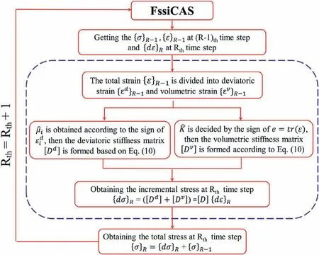
Fig.1.Algorithm flowchart of the constitutive model in FssiCAS.

Fig.2.A single brick 8-node element model and its applied boundary conditions on E, F, G and H.
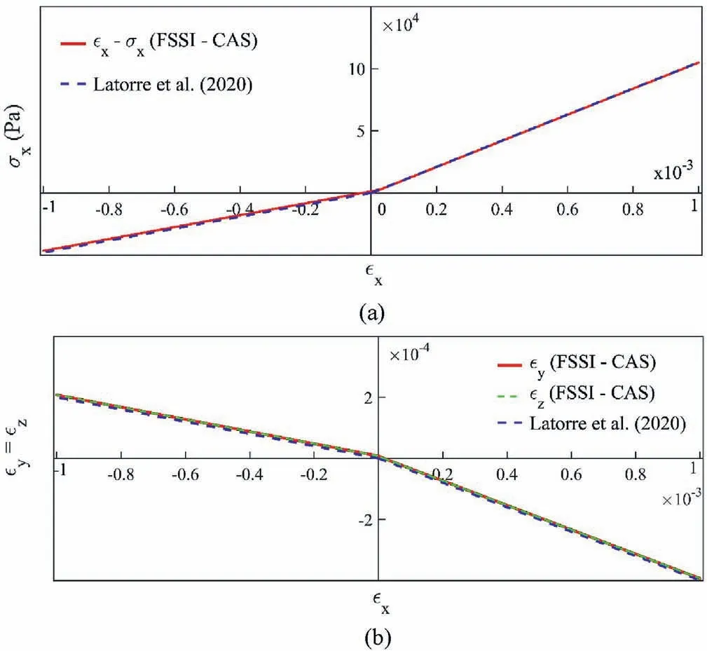
Fig.3.Comparison between the results of FssiCAS incorporating the uncoupled straindriven constitutive model and the results of Latorre and Montáns (2020): (a)Responding curve for the uniaxial strain x and uniaxial stress σx, and (b) Responding curve for the uniaxial strain x and transverse strain y = z.
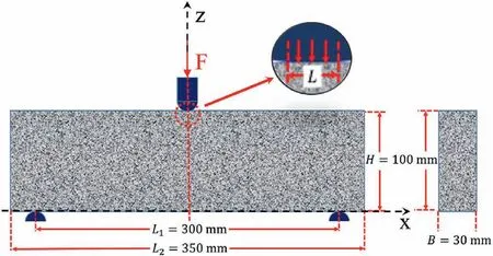
Fig.4.Configuration of the three-point bending (TPB) test utilized in this study.
It is seen in Fig.5 that the contact length L has a significant effect onxxin the compressive zone on the central cross-section of the beam.However, the impact onxxin the tensile zone which is below the neutral plane(a plane on whichxx= 0 in the beam)is minor.When the contact length L <10 mm, there is an apparent stress concentration effect near the loading head, and the distribution ofxxon the central cross-section of the beam is nonlinear.When L >10 mm, although the stress concentration is weakened,the field distribution ofzzin the zone beneath the loading head is significantly affected due to the large loading area.Finally, the loading head with a contact length L = 10 mm is selected to perform the subsequent numerical tests.It is worth noting that,when L∈[2,14]mm,the position of the strain neutral plane(xx=0)is at the position of z = 0.06 m rather than at the half height of the beam, i.e.z = 0.05 m, as point A in Fig.5.It is certainly contradictory with the assumption in the classical beam theory that the neutral plane must traverse the centroid of cross-sections of the beam if it is a single-modulus material.To explore the mechanism,a comparative case is specially set up.In this case, a uniform distribution load (F = 6 kN; P = 666.67 kPa) is exerted on the whole upper surface of the beam, i.e.in the range x∈[-0.15,0.15] m,where L=300 mm.It is found in Fig.5 that there is a perfect linear relationship forxxon the central cross-section.More importantly,the position of the strain neutral plane coincides with the centroid of the cross-section, i.e.z = 0.05 m, as the point B in Fig.5.The above results show that the stress concentration effect caused by the loading head has significantly affected the position of the strain neutral plane (xx= 0) inside the beam used in the three-point bending test.Therefore, it is incorrect to assume that the strain neutral plane shifts the centroid of the cross-sections of the beam in the classical beam theory, even though the beam is singlemodulus material.
3.2.Effect of bi-modulus property on the TPB beam
In this study,Cases A and B are adopted as comparative cases to systematically investigate the effect of the bi-modulus property of materials on the deformation characteristics of the beam used in the three-point bending test.Four-node finite elements are used in the numerical analysis, and the number of elements is 35,000.
3.2.1.Distribution and magnitude of displacement
As shown in Fig.6, the distribution pattern of displacements inside the beam is basically identical, but the magnitude of the displacement is significantly different in Cases A and B.if the bi-modulus property of materials is considered, then the vertical displacement w of the beam increases significantly.To ensure the reliability of the following analysis, it is necessary to demonstrate the correctness of the results in Case A.For a short and tall beam(the height-span ratio is 1:3)as shown in Fig.4,the effect of shear stress inside the beam should not be ignored.Therefore, the Timoshenko beam theory (Timoshenko, 1921) could be utilized to predict the vertical displacement w on the central cross-section of the beam used in the three-point bending test,which is formulated as Eqs.13-16 (Dym and Shames, 1973; Li et al., 2019).The parameters and results are listed in Table 2.

Table 1 Elastic parameters used in the numerical three-point bending tests.
where w is the vertical displacement of the cross-section at x = 0 m, F is the exerted load by the loading head, L1is the distance between the two supports on the bottom of beam, E is the elastic modulus, ν is the Poisson’s ratio, I is the inertia moment of the cross-section,G is the shear modulus,A is the cross-sectional area,and k is the shear correction coefficient (Jensen,1983).
It can be seen in Fig.6e that the vertical displacement w in Case A is 30.33 μm.In Table 2, the predicted result by Eq.(13) is 29.87 μm.The relative error between them is only δ = 1.52%.This relative error has been demonstrated by Brancheriau et al.(2002)that it is acceptable.It is indicated that the numerical results in this study are reliable.
To further illustrate the effect of the bi-modulus property on the displacement distribution in the three-point bending beam, the relative difference distribution of displacements between Cases A and B is established, as shown in Fig.7.The absolute values of the relative error between uAand wAand the corresponding values in Case B, i.e.uBand wB, are calculated by
where uA, wAand uB, wBare the horizontal and vertical displacements in Cases A and B, respectively.
As shown in Fig.7a, the value of |δu| in the range of z∈[0.07,0.1]m is relatively low,and the average value is 36.8%.But the value of |δu| in the range of z∈[0.04,0.06]m is very considerable,with an average value of 276.5%.It shows that the bi-modulus property of material has relatively little effect on the horizontal displacement in the upper region of the beam but has a considerable impact on the horizontal displacement near the centroid of the cross-section(z = 0.05 m).Besides,it can be seen in Fig.7b that the value of |δw| is very great in the zone of |x| ≥0.14 m; while it is stable and uniform in the zone of x∈[-0.14,0.14]m,about 73.7%.To sum up,the bi-modulus property of materials has a non-negligible effect on the displacement inside the three-point bending beam.
3.2.2.Distribution and magnitude of stresses
As shown in Fig.8,the stress distributions pattern in Cases A and B are similar, but their magnitude differs significantly.To further explore the effect of the bi-modulus property on the internal stress field of the three-point bending beam,the relative errors of stresses between Cases A and B can be defined by Eq.(18), and the distributions of the relative errors are shown in Fig.9.
where σAis the stress in Case A, and σBis the stress in Case B.
It can be seen in Fig.9 that |δσ| is relatively small in most zone inside the beam, about 36.8%, but it exceeds 200% in some local regions.In Fig.9a,|δσxx|is the greatest in a strip region,i.e.z∈[0.04,0.06]m.In Fig.9b,except for the four arc-shaped shear bands,|δσzz|are basically constant, about 36.8% in the rest zone.As shown in Fig.9c, |δτxz| remains constant within x∈[- 0.15, 0.15]m, about 36.8%.To explain the mechanism for the above significant differences, the distributions of the horizontal stress σxxand vertical stress σzzon the central cross-section of the beam are compared between Cases A and B.The results are illustrated in Fig.10.
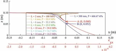
Fig.5.Effect of the size of the loading head on the distribution of xx on the central cross-section x = 0 m of the beam (front view is shown).
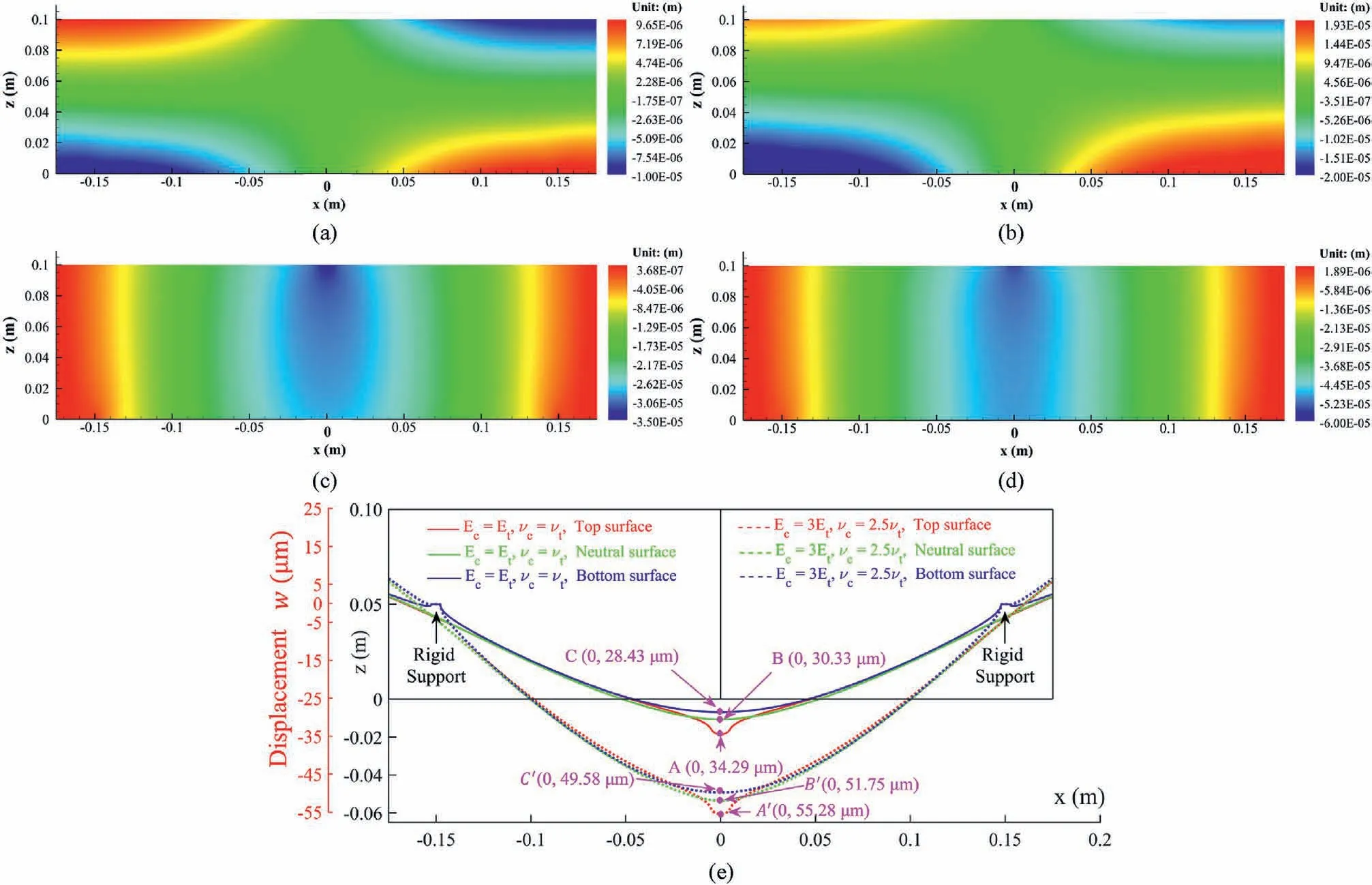
Fig.6.Comparison of the distributions of displacement between Cases A and B:(a)u in Case A;(b)u in Case B;(c)w in Case A;(d)w in Case B;and(e)Vertical displacement w on the top surface, neutral plane, and bottom surface of the beam.
It can be seen in Fig.10 that the distributions and magnitude of σzzin the two cases are almost the same, but there is a significant difference on σxx.In Case A, the stress neutral plane (σxx= 0) is located at the point B (z = 0.052 m).In Case B, the stress neutral plane is at point A (z = 0.063 m).It is indicated that the stress neutral plane in Case B moves upward compared to that in Case A.Due to this upward movement of the stress neutral plane,the stress state inside the beam changes significantly in the zone of z∈[B,A].This zone, i.e.z∈[B,A], is subjected to compressive stress in the xdirection in Case A.However, due to the movement of the stressneutral plane in Case B,the stress state in this zone becomes tensile.
Based on the above demonstration, it is indicated that the bimodulus property of materials has a significant and nonnegligible effect on the stresses, strains and displacements in the three-point bending beam.Besides,the stress-neutral plane(σxx=0)of the beam with bi-modulus property is not located at the halfheight of the beam.Therefore, it is not appropriate to apply the Euler-Bernoulli beam theory (Bauchau and Craig, 2009) and Timoshenko beam theory (Timoshenko,1921) to study the stress and deformation characteristics of three-point bending beam which has the bi-modulus property.
3.3.Parametric study
Since the Etand νtare varied simultaneously in Cases A and B,it is impossible for us to distinguish the independent effects of Etand νton the significant differences presented above.Hence,a series of parametric studies is conducted to investigate the independent impacts of Etand νtin this section.
3.3.1.Effect of Et
Here, five control cases are designed to investigate the independent influence of the tensile elastic modulus Eton the stress and deformation characteristics inside the three-point bending beam.The material parameters are set as: Ec= 60 GPa,νc= 0.25,νt=0.25,Et=20 GPa,30 GPa,40 GPa,50 GPa and 60 GPa,respectively.The numerical test results are shown in Fig.11.
It can be seen in Fig.11 that the tensile elastic modulus Ethas a significant effect on the stress, strain and vertical displacement inside the beam, thus the impact of Etshould not be ignored in numerical simulation and theoretical analysis.
3.3.2.Effect of νt
Similarly, five control cases are designed to study the independent influence of the tensile Poisson’s ratio νt.The material parameters are as: Ec= 60 GPa,νc= 0.25,Et= 60 GPa, νt= 0.1,0.15, 0.2, 0.25 and 0.3, respectively.The numerical test results are shown in Fig.12.
As illustrated by Fig.12, the tensile Poisson’s ratio νthas little influence on the distributions of the stress and strain on the central cross-section,and the vertical displacement on the neutral plane of the three-point bending beam.Therefore,it is feasible to adopt the hypothesis of νc= νtunder certain conditions.
4.A new method to measure Et
Since the operation in the three-point bending test is relatively easy during the test, it is usually utilized to measure the tensile strength,and sometimes the tensile elastic modulus of materials in recent years (Zhang and Yu, 2019).However, due to theshortcomings of the following two aspects,the measured Etby the three-point bending test is not accurate enough.Firstly, when the three-point bending beam subjected to a concentrated force F is simplified into a simply supported beam that could only bear a bending moment M, the influences of the shear stress τxzand vertical stress σzzin the beam are ignored.Therefore, it is not accurate to estimate the vertical displacement w of the beam according to the Euler-Bernoulli beam theory or Timoshenko beam theory.Secondly, the stress concentration effect caused by the loading head significantly affects the distributions of the stress,strain and displacement on the central cross-section of the beam.As a result, their distributions on the central cross-section are nonlinear.Therefore, some inevitable errors will be caused if the three-point bending test is applied to measure the tensile elastic modulus of materials according to the vertical displacement w on the central cross-section or the strainxxon the lower surface of the beam.To overcome these shortcomings in the three-point bending test,this study proposes a new method to measure the Etbased on the four-point bending test.Through numerical analysis,it is found that when the recommended geometry of beam in ASTM C78(2002)is utilized,i.e.the height-span ratio (the ratio of the height of the beam to the distance between the two supports on the bottom of the beam)H/L1= 1/3,there is still a considerable shear stress τxzinside the beam utilized in the four-point bending test.Therefore,it is necessary to find a beam model with an appropriate height-span ratio for the four-point bending test.
4.1.Selection of height-span ratio
To find a reasonable size for the beam model utilized in the fourpoint bending test, the ratio of the length of the bending beam L1and the distance between the two loading heads L3, as shown in Fig.13,are set as 1/6,1/3,1/2 and 2/3,respectively,and the heightspan ratio H/L1is set as 1/3,1/4,1/5 and 1/6,respectively.The input parameters are set as the resultant force F = 6 kN,Ec= Et=60 GPa,νc= νt= 0.25.The distributions of the shear stress τxzand vertical stress σzzon a cross-section are shown in Figs.14 and 15, respectively.

Fig.7.Relative difference distribution of displacements between Cases A and B: (a) |δu| and (b) |δw|.
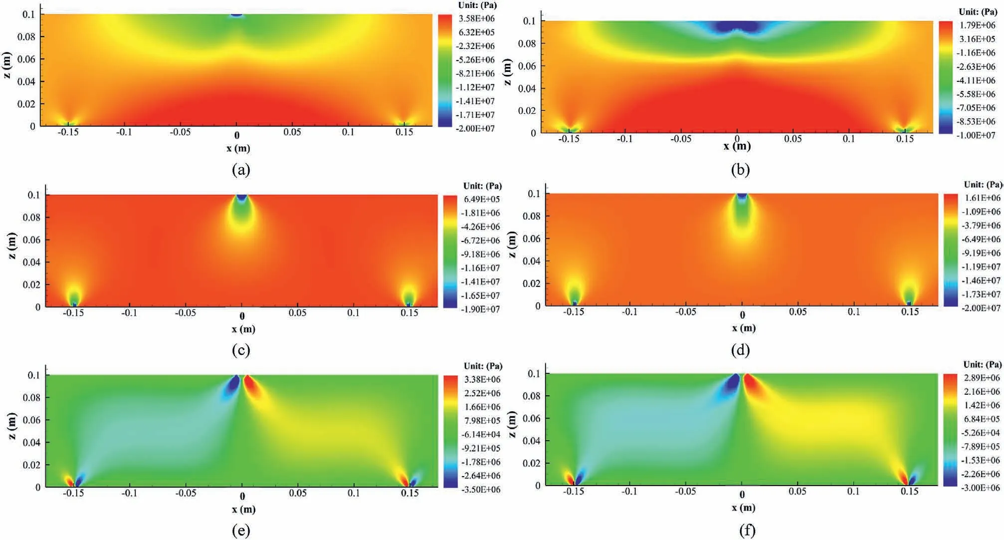
Fig.8.Comparison of the stress distributions between Cases A and B: (a)σxx in Case A, (b)σxx in Case B, (c)σzz in Case A, (d)σzz in Case B, (e)τxz in Case A, and (f)τxz in Case B.
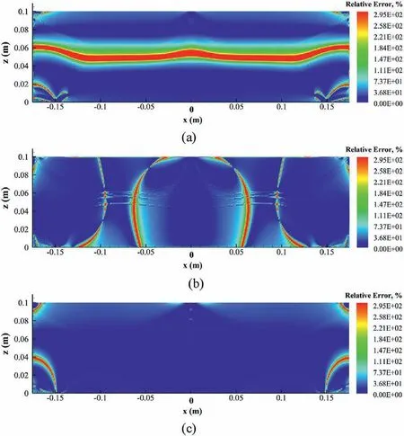
Fig.9.Relative difference distributions of stress between Cases A and B: (a) |δσxx|, (b)|δσzz|, and (c) |δτxz|.
As illustrated in Figs.14 and 15,the height-span ratio(H/L1)and the ratio of L3/L1both have a significant effect on the stress distributions within the range of x∈[-0.004 m,0.0004 m] (about the length of a strain gauge).When L3/L1is constant, the absolute values of σzzand τxzreduce with the increase of L1.when the H/L1is constant, the absolute values of σzzand τxzalso reduce with the increase of L1.It is observed that when L3/L1=2/3 and H/L1=1/6,the shear stress τxzand vertical stress σzzare close to zero in the range of x∈[- 0.004 m,0.0004 m].Under this situation, there is a pure bending section formed in the middle part of the beam.Therefore,it is reasonable to set the geometric model of the beam with L3/L1=2/3 and H/L1=1/6 for the subsequent numerical tests.
4.2.Illustrative examples
A numerical test is designed to check further whether the defects of the three-point bending model can be overcome effectively in the four-point bending model with L3/L1= 2/3 and H/L1=1/6.The input parameters are set as:the resultant force F = 6 kN,Ec=Et= 60 GPa,νc= νt= 0.25.The stress distributions in the beam are shown in Fig.16.
As shown in Fig.16, the distribution of σxxis layered and symmetric about the half-height of the beam (z = 0 m), and the magnitude varies linearly in the zone of -0.04 m <x <0.04 m,-0.05 m <z <0.05 m.Besides,σzzand τxzin this zone are much less than σxxand close to zero.Therefore, the above results can prove that the adverse influence of the stress concentration effect caused by the loading head on the stress distribution on the central cross-section of the beam (x = 0 m) can be effectively eliminated in the four-point bending test.The distributions of stresses and strains on the central cross-section under different conditions are compared to study the independent impacts of Etand νt, as illustrated in Fig.17.
It can be seen in Fig.17 that the distribution of σxxon the central cross-section has a bilinear characteristic under different conditions.It should be noted that the σzzon the central cross-section under different conditions are not equal to the theoretical solution,i.e.σzz= 0,due to the inevitable error in numerical analysis.However, the σzzis small enough compared with the value of σxx.Therefore, we can consider that the zone, i.e.-0.04 m <x <0.04 m,-0.05 m <z <0.05 m,only bears a bending moment M.In other words,this zone is a pure bending zone.
As shown in Fig.17a,the position of σxx= 0 andxx= 0 on the central cross-section (x = 0 m) moves upward from z = 0 m to z = 0.0115 m with the decrease of Et.This result again proves that the neutral plane and the centroid of the central cross-section of the beam do not coincide for bi-modulus materials.Furthermore,the variation of Etmakes the σxxin the tensile and compressive zone on the central cross-section of the beam change linearly with different slopes dσxx/dz (bilinear characteristic).However, the slopes dxx/dz ofxxmaintain constant on the whole central crosssection.Based on the above recognition,the position of the neutral plane on the central cross-section of the beam can be determined by the absolute value of the compressive straincxxon the upper surface of the beam and the absolute value of the tensile straintxxon the bottom surface of the beam, and its expression is

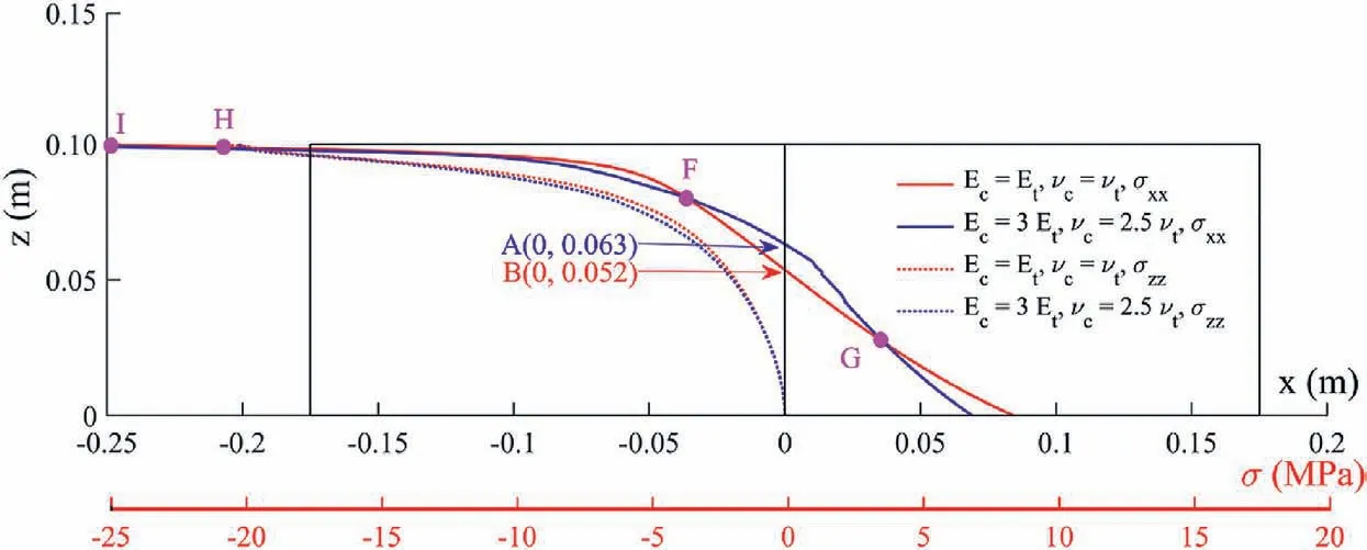
Fig.10.Comparison of the stress distribution on the central cross-section x = 0 m (front view is shown).
Besides, it is observed in Fig.17a thatxxvaries linearly with a constant slope dxx/dz on the central cross-section (x = 0).In contrast,zzin the horizontal tensile and compressive zones varies linearly with different slopes dzz/dz.In the compressive zone,the smaller the tensile elastic modulus Etis, the greater the variation slope ofzzis.In the tensile zone, the smaller the tensile elastic modulus Etis,the less the slope ofzzis,but the difference among these slopes is not significant.
It can be seen in Fig.17b that the tensile Poisson’s ratio νthas a slight effect on the horizontal stress σxx, vertical stress σzzand horizontal strainxxon the central cross-section of the beam.But the impact of νtonzzin the tensile zone is significant due to Poisson’s effect.According to the Euler-Bernoulli beam theory(Bauchau and Craig, 2009) and the generalized Hooke’s law(formulated as Eq.(22)), there is a linear relationship betweenxxandzzon the central cross-section of a pure bending beam.Therefore, the difference inzzin Fig.15b is caused by Poisson’s effect.
where M is the bending moment on the pure bending section in the four-point bending beam, and H is the section height of the fourpoint bending beam.
In summary, the application of the four-point bending beam shown in Fig.17 can effectively eliminate the stress concentration effect caused by the loading head.Thus, the horizontal stress σxxand horizontal strainxxon the central cross-section of the beam obey the linear or bi-linear distribution characteristics.More importantly, it proves that the four-point bending test can be utilized to measure the tensile modulus Etof materials.
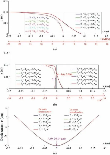
Fig.12.Effect of νt on the distributions of stress(a)and strain(b)on the cross-section x = 0,as well as on the distribution of the vertical displacement on the stress neutral plane(σxx = 0) and strain neutral plane ( xx = 0) (c).
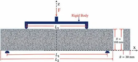
Fig.13.Diagram of the beam utilized in four-point bending test.
4.3.Measurement method
The overall idea and the specific steps of the measurement method are illustrated as follows: (1) The position of the neutral plane z0in the beam is determined according to the measured compressive and tensile strains on the upper and bottom surfaces on the central cross-section of the beam based on Eq.(21).(2)The maximum horizontal compressive stress (σcxx)maxand maximum horizontal tensile stress(σtxx)maxon the upper and bottom surfaces of the beam are determined through the force balance equation and moment balance equation.(3) The compressive and tensile elastic moduli of materials could be estimated synchronously according to the measurement formulation illustrated in the following.
As illustrated in Fig.18, the distribution of tensile and compressive σxxon the central cross-section of the pure bending beam have different slopes.Therefore, the following formulae can describe the relationship between σxxand the section height:
where b1is the slope of σxxin the horizontal compressive zone,b2is the slope of σxxin the horizontal tensile zone,σcxxis the compressive stress at any height in the compressive zone on the central section,and σtxxis the tensile stress at any position in the tensive zone on the central section.
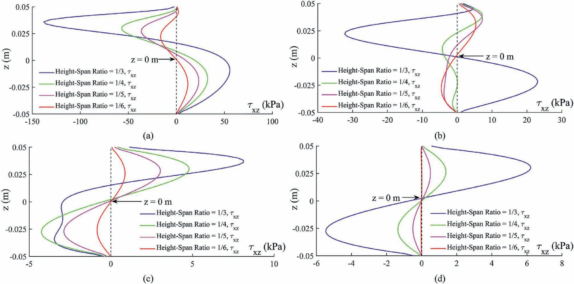
Fig.14.Distribution of the shear stress τxz on the cross-section x = 0.004 m with different values of L3/L1 and H/L1 (the shear stress on the cross-section x = 0 m is zero):(a) L3/L1 =1/6, (b) L3/L1 =1/3, (c) L3/L1 =1/2, and (d) L3/L1 =2/3.
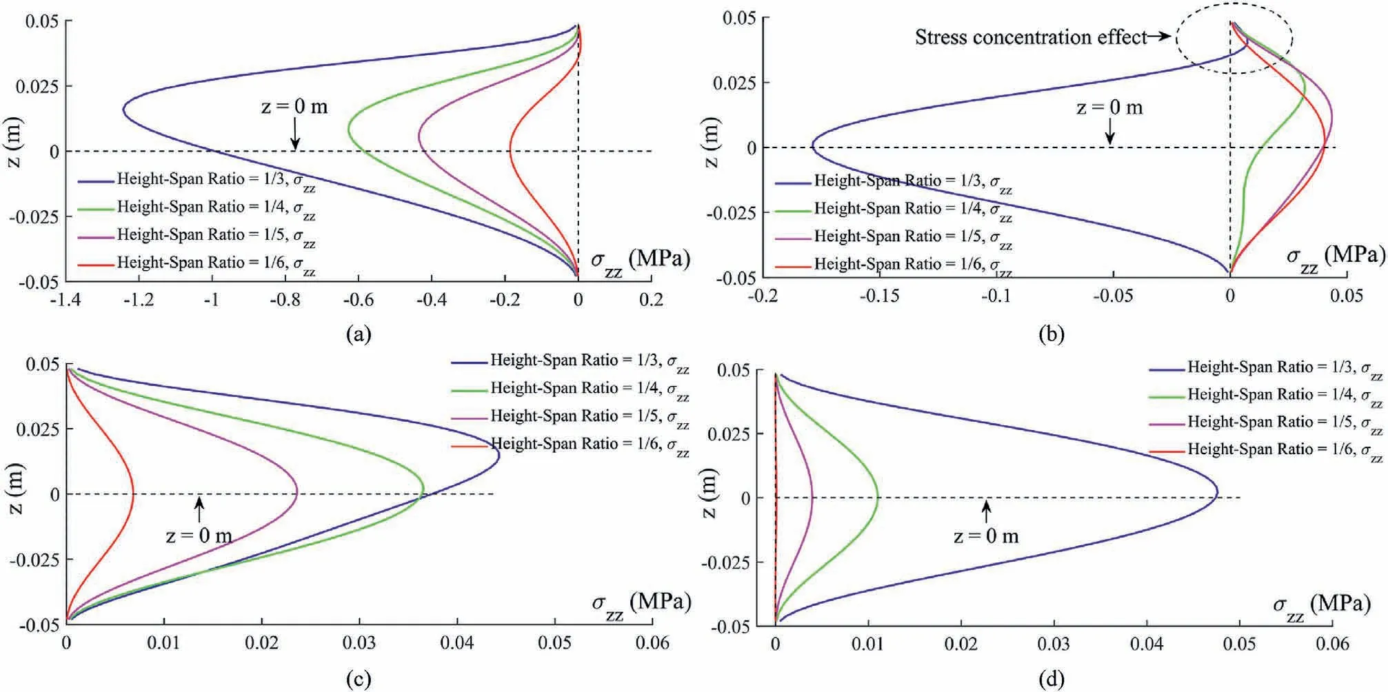
Fig.15.Distribution of the vertical stress σzz on the cross-section x = 0 m with different values of L3/L1 and H/L1:(a)L3/L1=1/6,(b)L3/L1=1/3,(c)L3/L1=1/2,and(d)L3/L1=2/3.
According to the stress distributions on the central cross-section inside a bending beam,the horizontal resultant force on the section is zero, which can be expressed as
where B is the thickness of the beam.In addition,the central crosssection (x = 0 m) is only subjected to a bending moment M rotating counterclockwise around the y-axis (perpendicular to the x-z plane and passing through the origin of coordinates).Therefore, the bending moment equation is formulated as (taking the clockwise as positive):
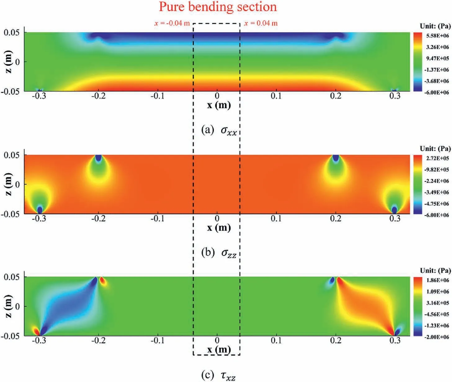
Fig.16.Distributions of stress in the four-point bending beam for the material with Ec = Et.
According to Eqs.(24)and(25),the expressions of b1and b2can be given as
Since the bending moment M on the central cross-section of the beam is indirectly generated by the resultant force F in the fourpoint bending test, their relationship is described as M =(F/2)[(L1-L3)/2] (L1is the distance between the two support points on the lower surface of the beam;L3is the distance between two loading points on the upper surface of the beam, as shown in Fig.13).Finally,the horizontal stress at any height z on the central cross-section of the beam (x = 0) is formulated as
Once the applied load F,the compressive straincxxat the center of the upper surface(x = 0 m,z = H/2)and the tensile straintxxat the center of the bottom surface (x = 0 m, z = - H/2) are measured in tests,then the tensile and compressive elastic moduli of the specimen can be estimated synchronically.The formulae are as follows:
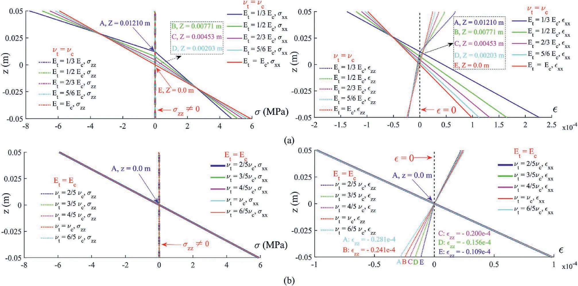
Fig.17.Effects of Et (a) and νt (b) on the distributions of stresses and strains on the central cross-section in the four-point bending test.
4.3.1.Numerical verification
To verify the reliability of the above-proposed measurement method, the numerical test verifications are conducted by taking the numerical results illustrated in Fig.17 as the typical cases.The relevant parameters and verification results are listed in Tables 3 and 4.
It can be seen in Table 3 that the measured compressive and tensile moduli by the proposed new measurement method are very close to the given modulus of materials.The maximum relative error is 6.62%, the minimum is only 0.53%, and the relative error increases with the reduction of Et/Ec.In Table 4,the relative error is within 2%, and the relative error gradually increases as νt/ νcreduces.
4.3.2.Experimental verification
Recently, Grazzini et al.(2023) investigates the bi-modulus characteristics of the NHL3.5 lime mortar through uniaxial tension and compression tests, the three-point bending test, and the four-point bending test.Based on the Euler-Bernoulli theory and Timoshenko theory,two formulations to measure the tensile elastic modulus of bi-modulus materials are also proposed by Grazzini et al.(2023).Here, the experimental data from Grazzini et al.(2023) is used to verify the reliability of the measurement method proposed in this study.The verification is performed by the following steps:
(1) Step 1: Estimating the Poisson’s ratio of the NHL3.5 lime mortar.Since the Poisson’s ratio of the NHL3.5 lime mortar was not measured by Grazzini et al.(2023),this study has to estimate the compressive Poisson’s ratio based on the mechanical parameters given by Grazzini et al.(2023),as well as the estimation method proposed by Swamy(1971)and Wang and Liang (2004).In addition, it has been known in Section 3.3.2 that the difference between the tensile Poisson’s ratio νtand compressive Poisson’s ratio νchas little influence on the characteristics of the stress and strain of bi-modulus materials.Therefore, it can be assumed that the νcof the NHL3.5 lime mortar is equal to the νt.Finally, the Poisson’s ratio of the NHL3.5 lime mortar is set as νc= νt= 0.24.
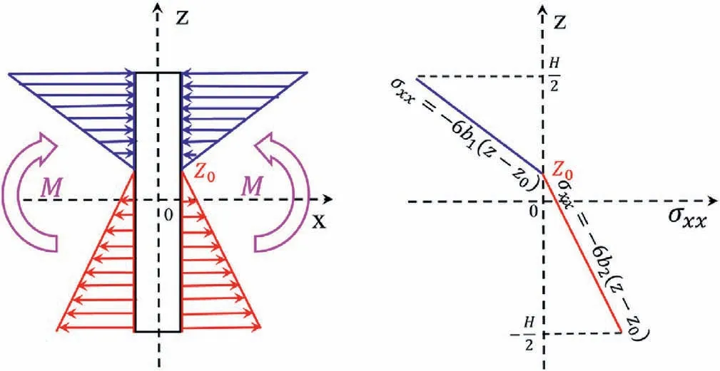
Fig.18.Diagrams of the compressive and tensile stresses on the central cross-section x = 0 of the beam.

Table 3 Elastic modulus measured by the value of strain illustrated in Fig.17a adopting Eqs.(28) and (29) (Ec = 60 GPa,νt = νc = 0.25).
(2) Step 2: Evaluating the reliability of the tensile elastic modulus measured by the uniaxial tensile test based on the load-displacement curves recorded in the four-point bending test.Since the values of the tensile elastic modulus measured by the uniaxial tensile tests for three different specimens are discrete, the reliability of the tensile elastic modulus (Et= 7422 MPa) given by Grazzini et al.(2023)could be evaluated through the numerical four-point bending test.If the load-displacement curve obtained in the numerical four-point bending test is close to the experimental data measured by Grazzini et al.(2023), the real tensile elastic modulus Etof the NHL3.5 lime mortar is indeed 7422 MPa.Otherwise,the real tensile elastic modulus of the NHL3.5 lime mortar can be optimally sought through some numerical four-point bending tests.The parameters used in the numerical four-point bending tests are Ec=14.384 GPa(given by Grazzini et al., 2023), νc= νt=0.24, and applied peak force F = 1369 N.The geometrical size of the beam model is 240 mm(length)×40 mm(height)× 40 mm(thickness), i.e.H/ L1= 40/180 = 1/4.5, and L3/L1= 60/180 = 1/3.It should be noted that the specimen size recommended in this study,i.e.H/L1= 1/6 and L3/L1= 2/3, is not used in the numerical tests,because the numerical beam model should be the same as that used by Grazzini et al.(2023).
(3) Step 3: Calculating the strain field inside the four-point bending beam through the numerical test, where the real tensile elastic modulus that has been optimally saught in Step 2 is used.Then the tensile elastic modulus of the NHL3.5 lime mortar can be measured through the method proposed in this study utilizing the numerical strain data.
(4) Step 4: Comparing the tensile elastic modulus measured by Grazzini et al.(2023) through three types of method (uniaxial tension test, Euler-Bernoulli theory, and Timoshenko theory, respectively) with the corresponding values measured through the method proposed in this study.The results are listed in Table 5.
(5) Step 5: Further evaluating the reliability of the method proposed in this study by comparing the measurement results from the two cases in which the recommended beam size (H/L1= 1/6 and L3/L1= 2/3) is utilized or not.The results are also listed in Table 5.
As shown in Fig.19, the load-displacement curves of the specimens 4 PB-LP-02 and 4 PB-LP-03 in Grazzini et al.(2023) are nonlinear during loading.Therefore, only the results of the specimens 4 PB-LP-01 and 4 PB-LP-04 are used in Step 2.Besides,if the Etis set as 7422 MPa in the numerical four-point bending test, the load-displacement curve obtained from the numerical test significantly deviates from the experimental data.Hence, it can be thought that the tensile elastic modulus obtained through the uniaxial tension test should be defective.When the elastic tensile modulus Etis set to 4000 MPa in the numerical four-point bending test,the load-displacement curve obtained from the numerical test is highly close to the experimental data.Therefore,it can be thought that the real tensile elastic modulus of the NHL3.5 lime mortar is about 4000 MPa.
As listed in Table 5, if the numerical four-point bending test is performed following H/L1= 1/4.5 and L3/L1= 1/3, the tensile elastic modulus Etmeasured by the method proposed in this study is 4.31 GPa(Beam size#1).Compared to the methods proposed by Grazzini et al.(2023),the reliability of the method proposed in this study is better, because the numerically measured value of Etis closer to the value obtained from the physical tests(4 GPa).What is more, if the recommended beam size is used to perform the numerical four-point bending test, the reliability of the proposed method will be further improved, where the relative error is only 4.08% for the Beam size #3.
Summarily, the above verification results show that the newly proposed measurement method in this study has a good reliability in the synchronous estimation of the tensile and compressive elastic moduli of bi-modulus materials.
5.Conclusions
In this study, the uncoupled strain-driven constitutive model proposed by Latorre and Montáns (2020) is used to systematically study the effect of the bi-modulus property on the bending performance of materials, and a new measurement method for Etis proposed.Based on the research results,the following conclusions are drawn:
(1) Under a complex stress state, i.e.when the tensile and compressive stresses co-exist, the bi-modulus property of materials has a significant effect on the stress, strain and displacement inside a bending beam with the bi-modulus property.Therefore, there is a significant error in the engineering design and numerical simulation if the bi-modulus property of materials is neglected.
(2) In the three-point bending test, the stress concentration effect caused by the loading head considerably impacts the distributions of stresses, strains, displacements and the position of the neutral plane inside the beam.Therefore, it is not appropriate to investigate the bending characteristics of a three-point bending beam utilizing the Euler-Bernoulli beam theory or Timoshenko beam theory.
(3) A beam with a height-span ratio of 1:6 can effectively eliminate the stress concentration effect caused by the loading head, and make the central cross-section only bear a pure bending moment in the four-point bending test.Therefore,σxxon the central cross-section of the beam could vary linearly or bi-linearly along with the height of the central crosssection.This characteristic provides a quite well condition to synchronously estimate the tensile and compressive elastic moduli of bi-modulus materials.
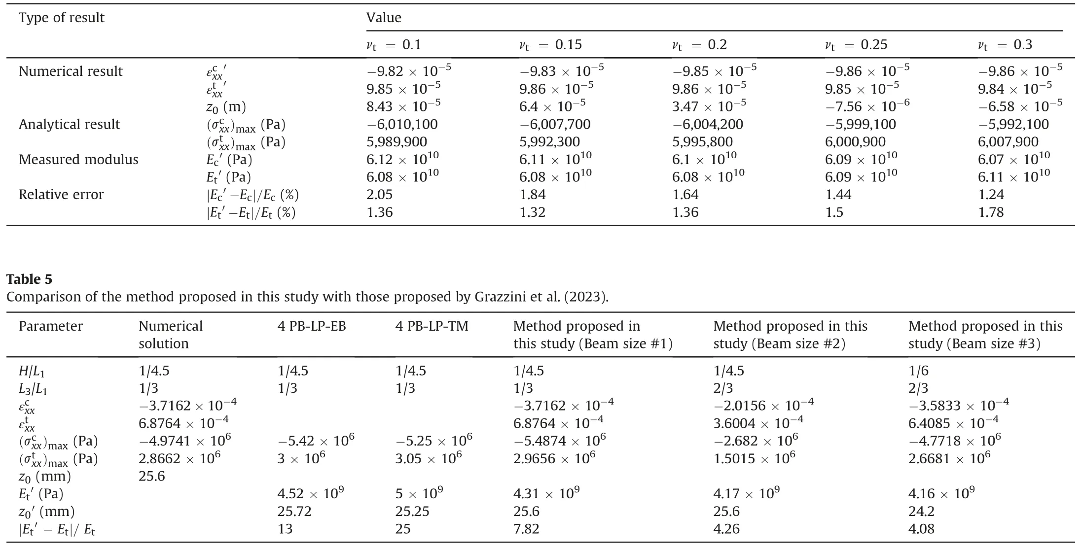
Table 4 Elastic modulus measured by the value of strain illustrated in Fig.17b adopting Eqs.(28) and (29) (Ec = Et = 60 GPa,νc = 0.25).
(4) The verification results from many numerical tests and experimental tests show that the new measurement method proposed in this study is reliable for synchronously measuring the tensile and compressive elastic moduli of bimodulus materials.It should be noted that the proposed new measurement method would be not applicable when the deformation of the bi-modulus materials moves into the elastoplastic phase.
(5) Compared with conventional test methods, the proposed new method not only takes the bi-modulus property into account but also can simultaneously measure the tensile and compressive elastic moduli.Therefore, the proposed new method should have a good application perspective in practice.However, compared with conventional direct tension/compression tests, it is not easy to prepare a beam specimen that is strictly rectangular,on which the front and rear lateral faces,as well as the top and bottom faces,should respectively be strictly parallel.
Declaration of competing interest
The authors declare that they have no known competing financial interests or personal relationships that could have appeared to influence the work reported in this paper.
Acknowledgments
The authors are grateful for the funding support from the National Key Research and Development Program of China(Grant No.2022YFC3102402), as well as from the National Natural Science Foundation of China (Grant No.51879257).
 Journal of Rock Mechanics and Geotechnical Engineering2023年10期
- Journal of Rock Mechanics and Geotechnical Engineering的其它文章
- A true triaxial strength criterion for rocks by gene expression programming
- Key issues in water sealing performance of underground oil storage caverns: Advances and perspectives
- Wetting-drying-freezing-thawing cycle effect on the hydro-mechanical behaviour of Yanji swelling mudstone
- Capability of discrete element method to investigate the macro-micro mechanical behaviours of granular soils considering different stress conditions and morphological gene mutation
- Permeability evolution mechanism and the optimum permeability determination of uranium leaching from low-permeability sandstone treated with low-frequency vibration
- Analysis of rockburst mechanism and warning based on microseismic moment tensors and dynamic Bayesian networks
