Piezoresistive behavior of elastomer composites with segregated network of carbon nanostructures and alumina
Chun-Yan Tang,Lei Liu,Kai Ke ,Bo Yin,Ming-Bo Yang,Wei Yang
College of Polymer Science and Engineering,Sichuan University,State Key Laboratory of Polymer Materials Engineering,Chengdu,610065,Sichuan,China
Keywords:Thermoplastic polyurethane Carbon nanostructures Alumina Conductive elastomer composites Stretchable strain sensor
ABSTRACT Electrically conductive elastomer composites (CECs) with segregated networks of conductive nanofillers show high potential in stretchable strain sensors due to balanced mechanical and electrical properties,yet the sensitivity at low strain is generally insufficient for practical application.Herein,we report an easy and effective way to improve the resistive response to low strain for CECs with segregated network structure via adding stiff alumina into carbon nanostructures (CNS).The CEC containing 0.7 wt% CNS and 5 wt% Al2O3 almost sustains the same elasticity (elongation at break of~900%) and conductivity (0.8 S/m) as the control,while the piezoresistive sensitivity is significantly improved.Thermoplastic polyurethane(TPU)composites with a segregated network of hybrid nanofillers (CNS and Al2O3) show much higher strain sensitivity (Gauge factor,GF=566) at low strain(45% strain) due to a local stress concentration effect,this sensitivity is superior to that of TPU/CNS composites(GF=11).Such a local stress concentration effect depends on alumina content and its distribution at the TPU particle interface.In addition,CECs with hybrid fillers show better reproducibility in cyclic piezoresistive behavior testing than the control.This work offers an easy method for fabricating CECs with a segregated filler network offering stretchable strain sensors with a high strain sensitivity.
1.Introduction
Electrically conductive elastomer composites (CECs) have attracted increasing attention for strain sensing applications in the human machine interface and structural health monitoring because of their piezoresistive response to mechanical stimuli[1–4].To date,CEC strain sensors based on thermoset and thermoplastic elastomers with tunable strain sensitivity and sensing strain ranges,fabricated via a series of strategies,have been widely reported in the literature[5–9].Among these strategies,the formation of a segregated conductive network of nanofillers at the elastomer interface seems quite attractive because of effective trade-off of mechanical properties and electrical conductivities,the use of low nanofiller content,as well as easy and environment-friendly fabrication[10–13].Therefore,strain sensors based on CECs with a segregated network of conductive nanofillers have shown potential applications in the field of flexible and stretchable electronics[14,15].
For stretchable strain sensor applications,high sensitivity is generally favorable because of the effective acquisition of electrical signals for the indication of strain stimuli [16,17].The formation of a segregated conductive network is able to build an elastic conductive network at low nanofiller content at the interface between elastomer particles [1].However,it is still a great challenge to achieve high strain sensitivity at low strains because of the slight deformation of the conductive network.To address this problem,hybrid nanofillers were used to construct a hybrid filler network so as to generate susceptible filler contacts due to nanofiller slippage under stretching[18–23].For instance,hybrid fillers of carbon nanostructures (CNS,also known as branched carbon nanotubes) and others such as carbon black (CB),carbon nanotubes (CNTs)and graphene,are able to achieve higher strain sensitivity at a strain less than 200% for thermoplastic polyurethane (TPU)-based CECs [22,24–26].The key to such a network design is increasing the filler-filler contact loss numbers under stretching caused by the differences in carbon nanofiller dimension and shape,as verified in conductive polymer composites with their resistive response to strain [23,24,27,28].Given that the practical value of maximum strain generated in the human body during body motion(≤55%)or in the infrastructure for structural health monitoring (≤10%),it is necessary to further increase the strain sensitivity of the foregoing systems at moderate strain for practical applications.
In general,it is possible to achieve high sensitivity at a strain less than 100%via the incorporation of micro-cracks in bilayer film strain sensors fabricated by the deposition of conductive nanomaterial layer on elastomer substrates[29–32].However,the durability and reproducibility of the fabricated sensors still need to be improved because of the weak interfacial bonding between elastomer substrate and the coated/deposed nanomaterial layer,especially at relatively large strain (e.g.,strain>10%).In contrast,trapping nanofillers by an elastomer matrix through either blending or heat-induced interfacial binding is relatively more effective for establishing a solid interfacial bonding between elastomer and nanofillers[10,33–37].However,this solution generally gives rise to the sacrifice of strain sensitivity due to limited contact loss between nanofillers under stretching due to robust elastomer-nanofiller bonding.Therefore,it is necessary to explore new strategies to build strain-susceptible but durable interfacial bonding to tune the strain sensitivity of stretchable strain sensors based on CECs with a segregated filler network.
Local heterogeneous structure can generate more contact loss of conductive fillers in the network because of uneven local stress distribution,i.e.,local strain concentration[38,39].In addition,it is reported that using hybrid fillers of carbon nanotubes and silica can tune piezoresistive behavior of polymer nanocomposites because of the volume exclusive effect [40–42].Although the incorporation of another filler(either electrically conductive or insulating) may improve the dispersion of conductive fillers in a polymer matrix[43–45],it will change the percolated structure of conductive fillers in polymer composites because of the separation of conductive fillers by insulating ones.As a result,it significantly increases the percolation threshold (ΦC) of conductive fillers for polymer nanocomposites in most cases[46–48].In addition,introducing the other filler will change the composite mechanical properties.These heavily rely on the filler dimension,elastic modulus and interfacial interaction between fillers [48–52].All the foregoing discussion indicates that it is possible to generate uneven local stress distribution in a segregated conductive network via the introduction of stiff particles during the building of conductive pathways in the filler networks.
This work investigated the effect of alumina on piezoresistive behavior of elastomer composites with segregated network structure.Mechanical and electrical properties of the TPU composites with varying content of CNS and its hybrids with alumina (CNS–Al2O3) were comparatively studied.Piezoresistive behavior of the CECs with only CNS and CNS–Al2O3was also investigated to uncover effects of alumina on the strain sensitivity and sensing strain ranges of the composites.The addition of alumina can significantly increase the strain sensitivity of the composites with a segregated network structure at low strain because of the local strain concentration effect,enabling the fabrication of strain-susceptible stretchable strain sensors in an easy and effective way.
2.Experiment
2.1.Materials and composite preparation
Thermoplastic polyurethane powders (mean size of~200 μm,Fig.S1)are supplied by Shanghai Jinjieyou High Tech Material Co.,Ltd,China.Carbon nanostructures(CNS,pellets or flake,70 μm long,10 μm thick,nanotube diameter of~9 nm and specific surface area (SSA) of 200 m2/g)were supplied by Cabot Corporation(MA,US).Commercially available Al2O3particles (Shanghai Bestry Performance Materials Co.,Ltd,China) with the diameter~2 μm and specific surface area of 1.27 m2/g were used as the secondary filler.All the materials are directly used without further purification.
For the preparation of TPU composites with only CNS,TPU powders and CNS pellets were added into an agate jar and mechanically mixed for 60 min at a rotation rate of 400 r/min by a planet type ball mill(QM3SP,Nanjing Chishun Technology Development Co.,Ltd,China).CNS content was kept as 0.1 wt%,0.4 wt%,0.7 wt%,1.0 wt% and 1.3 wt%,respectively.The foregoing mixture was further compression molded at 130°C for 3 min using a hot presser (Y-002,Zhengzhou craftsman machinery equipment Co.,Ltd,China) to get rectangular films(6.5 cm × 1 cm × 0.1 cm) for the subsequent characterizations.The corresponding composites were named TC 0,TC 0.1,TC 0.4,TC 0.7,TC 1.0 and TC 1.3,respectively.For the TPU composites with hybrid fillers,CNS (fixed at 0.7 wt%) and Al2O3(5 wt%,10 wt% and 20 wt%) are processed using the same procedure.For convenience,the TPU composites with hybrid fillers containing 0.7 wt%CNS plus 5,10 and 20 wt%alumina,were denoted as TCA 5,TCA 10 and TCA 20,respectively.
2.2.Characterization
A scanning electron microscope(SEM,JEOL JSM-5900LV,JP)is used to observe the network of nanofillers in the TPU matrix.All samples were sputtered with Platinum prior to SEM characterization.Uniaxial tensile properties were investigated using a universal tensile testing system(Instron 5567,USA) with a loading speed of 50 mm/min.Five samples were tested for each composition to obtain the average data.Resistance of pure TPU and composites are tested by high resistance meter (ZC36,Shanghai the 6thElectric Meter Factory Co.,Ltd,China)and electrometer(6517B,Keithley Instruments,Inc.,OH,US),respectively,to get the composite electrical conductivities.Piezoresistive properties of two types of TPU composites were tested using a home-made stretching machine and the electric signals were recorded via a digital source-meter (2400,Keithley Instruments,Inc.,OH,US).Cyclic piezoresistive behavior testing of the CECs was done using the same home-made apparatus with maximum strain of 10%at a strain loading rate of 2 mm/min for the TC 0.7 and TCA 10 composites.
3.Results and discussion
Original morphology of both fillers analyzed by SEM in Fig.S2 shows that alumina has a spherical shape with diameter of a few micrometers,while CNS has a typical branched geometrical structure.Fig.1 shows the SEM images of TPU particles,CNS and TPU,as well as the hybrids of TPU and CNS–Al2O3,respectively.Compared with neat TPU particles,the surface morphology of those containing fillers shows attachment of CNS and CNS–Al2O3on the TPU powder surface after ballmilling,respectively.In addition,exposure of CNS on the TPU surface indicates relatively sparse distribution of CNS on the TPU particle surface,while alumina tends to agglomerate on the TPU particle surface and exhibits loose contact with TPU particles.This is possibly due to their different geometric size and specific surface area,as introduced in the material section.However,the size of TPU particles varies over a wide range(Fig.1),and this will affect the morphology and thickness of the segregated network of fillers formed at the surface of TPU particles after compression molding.

Fig.1.SEM images of pure TPU particles,TPU particles with surface attachment of CNS and CNS–Al2O3.
Fig.2 shows the network structure of TPU composites with single and hybrid fillers.TPU composites with CNS show a typical segregated network structure (Fig.2a) and a relatively compact but blurred interfacial layer consisting of CNS and CNS-TPU penetrated composites (see the zoomed SEM image on the top right,Fig.2a).The interface between the CNS layer and TPU looks obscure,indicating good binding between CNS and TPU as reported in other CECs with segregated networks of CNS[11,12,22,25,33,53].In contrast,the addition of Al2O3increases the interfacial layer thickness of the segregated network structure because of the much larger size of the alumina particles(Fig.2b).Furthermore,the agglomeration of alumina is obvious at the TPU particle interface,which is consistent with Fig.1.However,cracks can be observed at the interface between TPU particles because of the agglomeration of alumina and the poor interfacial binding between TPU and alumina agglomerates by comparison with TPU and CNS(Figs.2a and 2b).This is likely due to the smaller SSA of Al2O3than that of CNS.

Fig.2.SEM characterization of (a) TC 0.7 and (b) TCA 10 composites.
Electrical conductivities of TPU composites with only CNS and CNS–Al2O3hybrids are shown in Fig.3.With increasing CNS content,the electrical conductivity of TPU composites significantly increases at low filler loading,while an electrical conductivity plateau appears at a filler content above 0.7 wt%.The insert in Fig.3a shows that the TPU composites with only CNS have a percolation threshold of 0.02 wt%,which is comparable with previous work on electrically conductive elastomer composites[11,12].It is worth noting that the composite TC 0.7 has an electrical conductivity of 0.86 S/m,which is favorable for stretchable and flexible electronic design.Therefore,0.7 wt% CNS was selected for the fabrication of TPU composites filled with hybrid fillers.Fig.3b shows that the addition of Al2O3gives rise to significant decrease of electrical conductivity,especially for high Al2O3loadings.Such an obvious conductivity decrease is due to the volume exclusion effect of insulating Al2O3reported in other systems with hybrid fillers[46,54,55].

Fig.3.Electrical conductivity of TPU composites filled with(a)various CNS contents and(b)fixed CNS content of 0.7 wt%plus various Al2O3 contents.The insert in Fig.3a is the plotting of conductivity versus (Φ-ΦC) showing the ΦC of TPU/CNS composites.
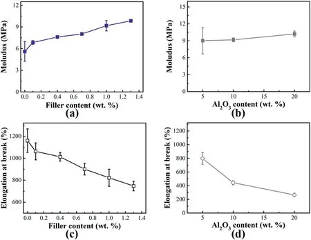
Stress-strain curves in Fig.S3 show that the addition of CNS and CNS–Al2O3significantly affects tensile properties of TPU and its composites.To clearly reveal the influence of fillers on mechanical properties of TPU composites with a segregated network structure,Young's modulus and elongation at break of TPU and its composites are presented in Fig.4.The addition of 0.1 wt%CNS leads to significant improvement in Young's modulus,while it becomes relatively low for CNS content between 0.1 wt% and 0.7 wt%.However,the modulus improvement becomes much more obvious after 0.7 wt%CNS.As seen in Fig.4b,the addition of Al2O3makes a limited contribution to the Young's modulus improvement,which is probably due to the aforementioned agglomeration of Al2O3at the TPU particle interface and relatively poor interfacial interaction between TPU and Al2O3agglomerates.Correspondingly,the elongation at the break deteriorates severely upon the use of CNS and Al2O3(Fig.4d)if compared with neat TPU and the TPU composites with only CNS(Fig.4c).

Fig.4.Mechanical properties of TC and TCA composites.(a,b)Young's modulus of TC and TCA composites with various filler contents.(c,d)Elongation at break for the TC and TCA composites with various filler contents.
The composites with 0.7 wt% CNS still have an elongation at the break up to 900%,which shows a 22% decrease compared with that of pure TPU.Intriguingly,the composites with CNS content less than 0.4 wt%show an elongation at the break above 1000%Thus the composites are still attractive for piezoresistive sensor design to some extent considering the ΦCof the composites of 0.02 wt %.However,for reproducible piezoresistive response,the composites with higher electrical conductivities will be more favorable[12,56,57].Therefore,the composites with 0.4 wt%and 0.7 wt%CNS are better candidates for the design of tensile strain sensors.This will be demonstrated in the following section.
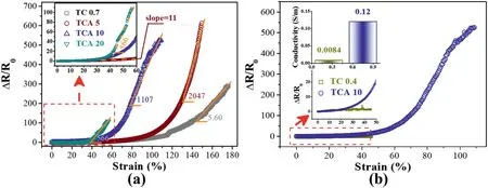
Fig.5 shows the TCA composites with varying content of Al2O3.By comparison with the TPU composites with only 0.7 wt%CNS,the addition of Al2O3significantly changes the piezoresistive behavior of TCA composites.Specifically,the combination of 5 wt% Al2O3and 0.7 wt%CNS gives rise to an obvious improvement of strain sensitivity after 80%strain.For strain within 40%,the sensitivity,which can be defined as the gauge factor(GF,GF=ΔR/R0×ε,where ΔR presents relative resistance change,R0and ε denote initial resistance and strain,respectively) [58,59],is relatively low(~11),indicated by the slope of TCA 5 in the insert(Fig.5a).For strain 40%to 60%,the composite TCA 20 has the highest GF as indicated by the slope of ΔR/R0to strain,which is ascribed to decreased electrical conductivity and deteriorated elongation at the break of the composites due to the volume exclusive effect of alumina.

Fig.5.(a)Relative resistance change plotted with strain for TC 0.7 and TCA composites.The insert zooms in on the curve for strain within 60%strain.(b)Comparison of the ΔR/R0 for TC 0.4 and TCA 10 composites which have different initial conductivity.The top insert represents the initial conductivity of TC 0.4 and TCA 10,while the bottom insert zooms in on the ΔR/R0-strain curves with 45% strain.
Given the trade-off between strain range and GF values,TCA 5 and TCA 10 are better candidates for flexible sensor application if comparing the strain sensitivity in the latter section of the ΔR/R0-strain curve.The GF for the composite TCA 10 is up to 566 for strain 40%~60%and 1107 for strain 60%~100%.These are superior to those in previous work[12,24].In addition,TCA 5 can sustain larger strain and its GF for strain 130%to 150%reaches 2047,which is superior to those CECs reported in the literature[11,12,60,61].Intriguingly,although the TC 0.4 composite has much lower electrical conductivity than that of the composite TCA 10(the upper insert in Fig.5b),the latter has much higher ΔR/R0at low strain(the lower insert in Fig.5b).It is believed that the composites with lower electrical conductivity correspond to a sparser conductive network and thus show higher ΔR/R0for the CECs,i.e.,higher strain sensitivity or larger GF values [23,24,58,59].Therefore,it can be concluded that the addition of alumina significantly affects the piezoresistive sensitivity of the CECs with a segregated network structure.
In principle,lower electrical conductivity is likely to increase the GF of the CECs with alumina.However,another plausible reason is that the presence of stiff Al2O3gives rise to local stress concentration (Fig.6),amplifying local strain to increase the strain sensitivity because of more loss of contacts between CNS under mechanical deformation and leading to enhanced tunneling resistance (Rtunnel) between CNS (Fig.6).This hypothesis can be verified by the occurrence of cracks in partial conductive paths built in the TPU particle interface under a strain of 100%,as manifested by SEM images(Fig.S4).Such an interpretation can be supported by the larger ΔR/R0of TCA 10 by comparison with TC 0.4(Fig.5b),though the latter has lower electrical conductivity.In contrast,the contacts between CNS are more difficult to lose thanks to the good TPU-CNS interfacial binding (Figs.2a and 6),as well as relatively firm contacts between CNS without local stress concentration effect contributed by Al2O3,resulting in limited increase in Rtunnelbetween CNS.Such an effect could be considered as a gain effect of insulating stiff particles in the hybrid filler network,and this gain effect is more remarkable at higher strain,as confirmed by Figs.5a and 5b.

Fig.6.Schematic illustrations of the tensile deformation of the segregated network of fillers formed between the TPU particles for the CECs with CNS along and CNS–Al2O3.

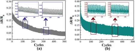
Fig.7.Relative resistance change versus cycles for the composites (a) TC 0.7 and (b) TCA 5 under maximum strain of 10%.The inserts in both figures are the amplification of ΔR/R0-cycle curves at cycles of 100–150 and 300–350,respectively.
To evaluate the stability of the strain sensor,we conduct around 500 testing cycles loading and unloading a strain of 10%.As seen in Figs.7a and 7b,the signal response to tensile strain for the TCA composites is also more significant than that in the TC composites for a consistent maximum strain of 10%.However,it is worth noting that the drifts of ΔR/R0are obvious for all testing cycles.This probably because of the break and rearrangement of the conductive network during cyclic stretching,the same as that reported in other CECs [18,19,24,62].The former composites have relatively better stability of resistance response to strain for all testing cycles,as indicated by the drifts of ΔR/R0values shown in the inserts in Fig.6a and b,respectively.Therefore,the addition of Al2O3also helps improve signal reproducibility,which will be beneficial for the practical strain sensing application.
4.Conclusions
The CECs with only CNS and hybrid fillers of CNS and Al2O3were fabricated via compression molding after mixing TPU powders with CNS or CNS–Al2O3in a ball mixer,respectively.The TPU/CNS composites have a very low percolation threshold (0.02 wt%) owing to the conductive network formed at the TPU particle interface.As a result,the CECs show good electrical conductivity and relatively high elongation at the break by comparison with neat TPU.After adding Al2O3,the composites still sustain high elongation at break and good electrical conductivity at low Al2O3(e.g.,5 wt%).However,both elongation at break and electrical conductivity deteriorate with increasing Al2O3content,which is because of severe agglomeration of micro-scale Al2O3particles and the electrically insulating characteristic of alumina.By comparison with the TPU/CNS system,the composites with hybrid fillers show much higher piezoresistive sensitivity at low strains and better reproducibility for cyclic ΔR/R0-strain performance testing.The plausible reason for such a phenomenon is the local stress concentration of stiff Al2O3at the surrounds of CNS.This work introduces an easy and effective way to fabricate CEC-based stretchable strain sensors with high piezoresistive sensitivity for human-machine interface application,as well as in the infrastructure of structural health monitoring.
Declaration of competing interest
There is no conflict of business interests in this paper.
Acknowledgements
The authors greatly acknowledge the financial support from the National Natural Science Foundation of China (No.51873126),the Fundamental Research Funds for the Central Universities,as well as the funding from the Science&Technology Department(No.2021YFH0123)of Sichuan Province.We are grateful for the Cabot Corporation for kindly providing the CNS nanomaterials for this research.We also thank Yuan-Ming Zhai (Analytical &Testing Center,Sichuan University) for useful discussion and suggestions.
Appendix A.Supplementary data
Supplementary data to this article can be found online at https://doi.org/10.1016/j.nanoms.2021.10.003.
- Namo Materials Science的其它文章
- A novel strategy of constructing 2D supramolecular organic framework sensor for the identification of toxic metal ions
- PtZn nanoparticles supported on porous nitrogen-doped carbon nanofibers as highly stable electrocatalysts for oxygen reduction reaction
- Flexible and electrically robust graphene-based nanocomposite paper with hierarchical microstructures for multifunctional wearable devices
- Surface reconstruction,modification and functionalization of natural diatomites for miniaturization of shaped heterogeneous catalysts
- DFT study on ORR catalyzed by bimetallic Pt-skin metals over substrates of Ir,Pd and Au
- Constructing P-CoMoO4@NiCoP heterostructure nanoarrays on Ni foam as efficient bifunctional electrocatalysts for overall water splitting

