
Surface reconstruction,modification and functionalization of natural diatomites for miniaturization of shaped heterogeneous catalysts
2023-10-22 08:59:12BowenLiTinWngQiujinLeRunzeQinYuxinZhngHuChunZeng
Namo Materials Science 2023年3期
Bowen Li ,Tin Wng,b ,Qiujin Le ,Runze Qin,b ,Yuxin Zhng ,Hu Chun Zeng,**
a Department of Chemical and Biomolecular Engineering,Faculty of Engineering,National University of Singapore,10 Kent Ridge Crescent,119260,Singapore
b State Key Laboratory of Mechanical Transmissions,College of Materials Science and Engineering,Chongqing University,Chongqing,400044,PR China
Keywords:Heterogeneous catalysis Diatomites Silica Catalytic materials Miniaturization Sustainable chemistry
ABSTRACT Since the discovery of mesoporous silica in 1990s,there have been numerous mesoporous silica-based nanomaterials developed for catalytic applications,aiming at enhanced catalytic activity and stability.Recently,there have also been considerable interests in endowing them with hierarchical porosities to overcome the diffusional limitation for those with long unimodal channels.Present processes of making mesoporous silica largely rely on chemical sources which are relatively expensive and impose environmental concerns on their processes.In this regard,it is desirable to develop hierarchical silica supports from natural minerals.Herein,we present a series of work on surface reconstruction,modification,and functionalization to produce diatomite-based catalysts with original morphology and macro-meso-micro porosities and to test their suitability as catalyst supports for both liquid-and gas-phase reactions.Two wet-chemical routes were developed to introduce mesoporosity to both amorphous and crystalline diatomites.Importantly,we have used computational modeling to affirm that the diatomite morphology can improve catalytic performance based on fluid dynamics simulations.Thus,one could obtain this type of catalysts from numerous natural diatoms that have inherently intricate morphologies and shapes in micrometer scale.In principle,such catalytic nanocomposites acting as miniaturized industrial catalysts could be employed in microfluidic reactors for process intensification.
1.Introduction
With the exciting discovery of MCM-41 in early 1990s,synthesis of mesoporous silica materials with uniform channels has been of great interest over the past three decades [1–3].As a result of this fruitful research endeavor,there have been numerous silica-based functional materials developed with different porosity,structure and overall morphology.Although the initial intention of the above research was targeted at extending applications of zeolites in heterogeneous catalysis,these porous silica materials have been adopted in many applications across vast technological fields,such as drug delivery,catalysis,bio-sensing,heavy metal removal,energy transfer,etc.[4–10].In particular,mesoporous silica has been proven to be a superior support for heterogeneous catalysis [6,11–13].After incorporation with various active components like metal nanoparticles or nanoclusters,the resulting nanoscale catalysts have exhibited a huge set of unique novel features and properties such as metal-support interaction,preventing particulate agglomeration or fusion,anti-leaching and molecular sieving effect.
Despite high rate of metal utilization and outstanding catalytic performances achieved with silica derived integrated nanocatalysts,cost of production has been one of major drawbacks that hinders their applications at industrial scale.Synthesis of silica support typically involves the usage of relatively costly silicon-alkoxide compounds such as tetramethyl orthosilicate (TMOS),tetraethyl orthosilicate (TEOS) or sodium silicate as silica sources[14–18],and the production of such precursors is usually expensive and not environmentally benign.Taking TEOS as an example,the industrial synthesis of TEOS was carried out using esterification reaction of SiCl4,followed by the Von Ebelman's route,which involves the use of alcohol solvent and energy intensive reactive distillation [19].As such,both the cost of production and associated environmental concerns need to be addressed for industrial scale production of mesoporous silica-supported catalysts.
In response to the above regards,naturally existing siliceous matters have been investigated actively as potential alternatives to the current chemical-plant-produced silica sources.These natural silica sources not only present a less costly method of production,but also help in building a greener and environmentally friendly eco-chemical system.There have been many reports of mesoporous silica with MCM-41 or SBA-15 like structures synthesized from a wide range of natural resources like minerals,coal fly ash,industrial and agricultural wastes,diatomites,etc.[20–27]In most of these reported cases,the silica source was extracted from the natural products via acid or alkali treatment.The resultant structures of mesoporous silica are largely determined by employed surfactants and reaction conditions and are mostly independent of their source materials.
Compare with other natural silica sources,diatomite solids have inherent structure-porosity properties that can be further utilized for fabrication of hierarchically porous materials [28–31].Moreover,diatomites are readily available with large reservoirs in abundant places across the globe [32,33].Also,its cost of production is much lower as compared to conventional silica sources produced from chemical plants[34].All these characteristic properties together make diatomites a very promising candidate for industrial scale production of hierarchically porous silica-based catalysts.
Currently,the utilization of diatomites could be roughly classified into two categories.Firstly,macroporous diatomites have already been directly used as supporting materials or templates to utilize the unique morphology[35–41].In this way,their advantages in fluid dynamics are utilized where there are no added catalytic benefits associated with mesoporous silica.When subjected to harsh reaction conditions,such catalysts may suffer from particulate aggregation,leaching of active component,etc.Secondly,there have been reports of using diatomites as a silica source to produce MCM-41 or SBA-15 like mesoporous silica in which the pore dimension is less than 10 nm[22,25,26,42].In this latter application,catalyst stability has been improved by mesopore formation.However,pristine diatomites are fully dissolved and their original morphology and porosity were totally lost during synthesis.As such,these diatomite-derived catalysts do not have the morphology related fluid dynamics advantages and will be experiencing substantial diffusional barriers due to the large ratio between channel length(in μm scale)and pore size (in nm scale).While using conventional silica precursors,advanced synthetic strategies have been developed to produce hierarchically porous silica supports to shorten the diffusion path and improve the catalytic performances [43].Similarly,one could achieve the fluid dynamics benefits together with merits of having mesoporous silica,if we could use diatomites as mesoporous silica precursor without damaging their original morphology and macroporosity.
In this work,we present the surface reconstruction,modification,and functionalization of naturally abundant diatomites to reengineer silica supports with hierarchical porosity and complex morphology (Scheme 1).In particular,we have developed a novel synthetic approach to partially reconstruct and modify the diatomites to acquire additional mesopores but without compromising their inherited shape and porosity.The resulting catalysts will retain the original fluid dynamic advantages of natural diatomites,while providing additional catalytic merits associated with mesoporous silica layer (e.g.,metal-support interaction,preventing particulate agglomeration or fusion,anti-leaching,etc.).To demonstrate the versatility of this transformative approach,two different preparative protocols targeting at both amorphous and crystalline diatomite samples have been further devised,respectively.More specifically,a one-pot synthetic route was tested for an amorphous diatomite with hollow cylindrical shape and perpendicular macropores (Scheme 1a).While preserving the morphology and macropores,a thin layer of mesoporous silica was generated on the entire surface of diatomite including macropores,achieving the desired hierarchical porosity.On the other hand,for the discus-like crystalline diatomite with perpendicular macropores,a two-step treatment process was developed to incorporate mesoporous silica to its pristine structure (Scheme 1b).The resulting samples with hierarchical porosity will have pristine macropores inherited from their natural diatomite morphology to facilitate rapid mass transfer while the newly introduced mesopores could effectively increase the specific surface area of these natural silica supports,providing strong metal-support interaction which inhibits metal aggregation or detachment,etc.These hierarchically porous silica supports were then functionalized by loading various noble metal nanoparticles through surface modification and evaluated for both liquid-and gasphase applications.Good catalytic activity and stability were observed,illustrating the potential of diatomites as a class of natural silica source to partially replace expensive organic silica precursors in producing hierarchically complex nanocatalysts,as naturally inherited intricate morphological structures of desired catalysts can be selected and attained easily at low costs of both source materials and manufacturing processes.

Scheme 1.Schematic illustrations for the synthesis of hierarchically porous catalysts from (a) amorphous hollow cylinder diatomite and (b) crystalline discus-like diatomite.The models are for illustration only and not drawn to scale.For the amorphous sample (a),one-pot synthesis has been developed to partially dissolve the natural diatomite into siliceous species which are then recondensed to mesoporous silica layer with the assistance of surfactant CTAB.For the crystalline diatomite(b),a two-step synthetic route has been devised.First,a strong alkaline environment is utilized to partially dissolve the crystalline diatomite,forming random aggregates of silica on the surface of diatomite.The pretreated sample is then subjected to a second treatment at lower pH together with CTAB,during which silica aggregates with ordered mesoporous channels are formed.In both cases,diatomite surfaces have become rougher after alkaline treatment while the pristine macroporosity and shape of the diatomites are preserved.Subsequent catalytic functionalization with noble metal nanoparticles is realized for the treated samples via surface grafting with–NH2 group to immobilize noble metal ions and reductive transformation to their metallic forms.
In the following,as a starting point,we first perform computational simulations to shed light on effects of carrier structures on detailed flow dynamics with macroporous diatomite samples.Based on our simulation results,the macroporous morphology of natural diatomites could effectively reduce reactor dead volume (caused by flow turbulence),increase mass transfer efficiency between catalyst and bulk fluid and posing a smaller resistance toward fluid flow.
2.Experimental section
2.1.Chemicals and materials
The following chemicals were used as received without further purifications: Amorphous diatomite (a-diatomite) was purchased from Mount Sylvia Pty Ltd (Queensland,Australia).Crystalline diatomite (cdiatomite) was obtained from Chengdu Kelong Chemicals Co.,Ltd(Chengdu,China).Sodium hydroxide (NaOH),cetyltrimethyl ammonium bromide (CTAB,≥96.0%),toluene (≥99.5%),3-aminopropyl trimethoxysilane (APTMS,≥98%),palladium (II) chloride (PdCl2,≥99.99%),poly(sodium-4-styrenesulfonate) (PSS,MW: 200000),zinc nitrate hexahydrate(Zn(NO)3⋅6H2O,ACS Reagent),2-methylimidazole(2-MeIM,≥99.0%),potassium carbonate (K2CO3,≥99%),iodobenzene(C6H5I,98%),phenylboronic acid(C6H5B(OH)2,95%),bromobenzene(C6H5Br,99%),iodoanisole(C6H4OCH3I,98%)and cyclohexene(C6H10,≥99%)were purchased from Sigma-Aldrich.Dodecane(CH3(CH2)10CH3,>99.0%) and styrene (C6H5CH––CH2,99%) were purchased from Alfa Aesar.
2.2.Endowing mesoporosity to amorphous diatomite (viz.,a-diatomite/mSiO2)
In a typical synthesis,30 mg ofa-diatomite was first dispersed in 30 mL of 0.005 M NaOH aqueous solution.In addition,109 mg of CTAB was added to the solution mixture.After an ultrasonic treatment,the homogeneous mixture was transferred into a Teflon-liner and sealed within a stainless-steel autoclave.Hydrothermal treatment was then carried out at 150°C for 12 h.Upon cooling in a fume hood,the precipitate was collected via centrifugation and washed twice with a 1:1 water ethanol mixture.The sample was first dried at 80°C and then calcined in static air at 550°C for 4 h at a ramp rate of 3°C⋅min-1to remove the CTAB template.
2.3.Transforming a-diatomite to spongy a-diatomite (viz.,sa-diatomite)
In a typical synthesis,30 mg ofa-diatomite was first dispersed in 30 mL of 0.01 M NaOH aqueous solution without using CTAB.After an ultrasonic treatment,the homogeneous mixture was transferred into a Teflon-lined stainless-steel autoclave.Hydrothermal treatment was then carried out at 120°C for 6 h.Upon cooling inside a fume hood,the precipitate was collected via centrifugation and washed twice with a 1:1 water ethanol mixture.The sample was then dried at 80°C and kept for further use.
2.4.Endowing mesoporosity to crystalline diatomite (viz.,c-diatomite/mSiO2)
In a typical synthesis,two hydrothermal steps were used.In the first step,250 mg of crystalline diatomite was dispersed in 40 mL of 1.0 M NaOH aqueous solution and stirred for 30 min.Then the solution was transferred into a 100 mL Teflon liner and sealed within a stainless-steel autoclave.Then,the autoclave was transferred to a rotating electric oven(at a rotation speed of 4 rpm)and the hydrothermal treatment was carried out at 150°C for 30 min.After that,the autoclave was cooled to room temperature with running tap water.The resulting mixture was directly used for the next step without centrifugation.In the second step,303 mg of CTAB was added to the resultant mixture and magnetically stirred for 30 min.The pH value of this solution was adjusted to 10 using a 2.0 M H2SO4aqueous solution.After that,the solution was transferred into a 100 mL Teflon liner and sealed within the stainless-steel autoclave again,and another hydrothermal treatment was carried out at 100°C for 4 h inside the same rotating oven (also at 4 rpm).Upon cooling to room temperature within the oven,the precipitate was collected via centrifugation and washed twice with a 1:1 water ethanol mixture.The sample was first dried at 80°C inside an oven and then calcined in static air at 550°C for 6 h with a ramp rate of 3°C⋅min-1to remove the CTAB template.
2.5.Loading Pd to a-diatomite/mSiO2 (viz.,a-diatomite/mSiO2@Pd)
Typically,100 mg ofa-diatomite/mSiO2sample was dispersed in a mixed solution containing 15 mL of toluene and 0.5 mL of APTMS.A homogeneous dispersion was obtained via sonication and refluxed at 110°C overnight for 12 h.The product,amino functionalizeda-diatomite/mSiO2,was collected via centrifugation and washed twice with a 1:1 water ethanol mixture.The sample was then dried in oven at 80°C.40 mg of such sample was redispersed in 6 mL of 3.0 mM PdCl2aqueous solution and stirred at room temperature for 4 h.The sample was then collected via centrifugation and washed twice with a 1:1 water ethanol mixture.Upon drying in an electrical oven at 80°C,the sample was heattreated in H2atmosphere at 300°C for 3 h with a ramp rate of 3°C⋅min-1and H2flow rate of 50 mL⋅min-1,respectively.The final sample with loaded Pd nanoparticles (NPs)was denoted asa-diatomite/mSiO2@Pd.
2.6.Loading Pd to sa-diatomite (viz.,sa-diatomite @Pd)
The synthetic procedure was identical to that of Section 2.5,except 100 mg ofsa-diatomite was used instead ofa-diatomite/mSiO2.
2.7.Loading metals to c-diatomite and c-diatomite/mSiO2 (viz.,cdiatomite@M and c-diatomite/mSiO2@M;M= Pd,Pt and Ag)
The synthetic procedure was identical to that of Section 2.5,except 100 mg ofc-diatomite/mSiO2was used instead ofa-diatomite/mSiO2.In addition to loading of Pd NPs,Pt and Ag have also been successfully loaded to thec-diatomite/mSiO2support,using 6 mL of 3.0 mM H2PtCl6and 3.0 mM AgNO3aqueous solutions as metal precursors.The products were named asc-diatomite/mSiO2@Pd,c-diatomite/mSiO2@Pt andcdiatomite/mSiO2@Ag,depending on the metal loaded.By adjusting the concentration of Pt precursor solution,loading of Pt NPs with different weight percentages has been realized(0.9–4.4 wt%).While keeping all other parameters unchanged,the concentration of Pt aqueous solution used was adjusted to 0.5 mM,1.0 mM,1.5 mM,2.0 mM and 3.0 mM respectively.The resulting samples were denoted asc-diatomite/mSiO2@Pt-n,wherenrepresents the concentration of Pt aqueous solution used in Pt deposition (i.e.,n=0.5,1.0,2.0 and 3.0 mM H2PtCl6,respectively).The final Pt loading amount was measured by ICP-OES to be 0.9 wt % forc-diatomite/mSiO2@Pt-0.5,1.8 wt % forc-diatomite/mSiO2@Pt-1.0,2.8 wt%forc-diatomite/mSiO2@Pt-1.5,4.0 wt%forcdiatomite/mSiO2@Pt-2.0 and 4.4 wt % forc-diatomite/mSiO2@Pt-3.0.Loading of Pt to naturalc-diatomite has also been realized by using 100 mg ofc-diatomite instead ofc-diatomite/mSiO2.For example,6 mL of 3 mM H2PtCl6aqueous solution was used for the Pt deposition in this case.The Pt loaded sample was denoted asc-diatomite@Pt with 1.5 wt % Pt loading.
2.8.Adding ZIF-8 overcoat on sa-diatomite@Pd (viz.,sadiatomite@Pd@ZIF-8)
10 mg ofsa-diatomite@Pd was dispersed in 10 mL of 1 wt % PSS aqueous solution and sonicated for 0.5 h.The solution was then centrifuged and washed twice with a 1:1 water ethanol mixture.The centrifugal sediment was transferred to 1.5 mL of 0.45 M Zn(NO)3⋅6H2O in methanol solution and stirred magnetically for 30 min.Then,2 mL of 0.1 M 2-MeIM in methanol solution was added dropwise into the above mixture solution.The sample vial was placed in an ice bath and stirred for 1 h.Another 2 mL of 2-MeIM methanol solution was then added and the mixture was stirred for another 1 h at room temperature.Finally,the precipitate was collected via centrifugation and washed twice with a 1:1 water ethanol mixture.The collected sample was dried at 80°C inside an oven to obtain the finalsa-diatomite@Pd@ZIF-8 sample.
2.9.Liquid-phase Suzuki coupling reaction with Pd loaded diatomite samples
In a typical synthesis,20 mg of catalyst was introduced to the solution mixture containing 10 mL of ethanol,1 mmol of phenylboronic acid,2 mmol of potassium carbonate and 0.5 mmol of n-dodecane.The mixture was placed in a round bottom flask and heated to 85°C with an oil bath.Upon adding 0.5 mmol of aryl halide,the reaction was started and the liquid solution was sampled at different reaction times,filtered through a membrane and analyzed by gas chromatography (GC,Agilent 7890A equipped with a flame ionization detector (FID)).To understand the stability of different catalysts,sample catalyst was recovered by centrifuging after each reaction cycle and the recycled catalyst was dried in a vacuum oven for 30 min before subject to the next run.
2.10.Liquid-phase selective hydrogenation of alkenes with sadiatomite@Pd@ZIF-8
Typically,hydrogenation reaction was carried out using round bottom flask placed in oil bath.16 mg ofsa-diatomite@Pd or 20 mg ofsadiatomite@Pd@ZIF-8 catalyst was used to ensure the same Pd loading.The catalyst was dispersed in 5 mL of ethyl acetate and 2 mmol of styrene or cyclohexene was used as reactant.The reaction proceeded at 35°C with continuous H2bubbling at 50 mL⋅min-1.The reaction mixture was sampled at different time intervals,filtered through a membrane,and analyzed by gas chromatography (GC,Agilent 7890A equipped with an FID).
2.11.Gas phase CO2 hydrogenation to CO with c-diatomite/mSiO2@Pt
The CO2hydrogenation reaction was carried out using a horizontally placed continuous flow fixed bed reactor (3/8 in.stainless steel) using 200 mg of catalyst sample.Prior to the hydrogenation reaction,in situ H2reduction was carried out at 400°C for 1 h with H2flow rate of 50 mL⋅min-1to activate the sample.The reaction was conducted using a feed stream of CO2/H2/N2=24%/72%/4%,in which N2gas was used as an internal standard.While the reaction pressure was fixed at atmospheric pressure,the catalytic performance was analyzed with temperature ranging from 200°C to 400°C.The effect of Pt loading wt % and reactant gas feed rate was also evaluated while fixing the reaction temperature and pressure.The exhaust gas was measured by online gas chromatography (GC,Agilent 7890A equipped with a thermal conductivity detector(TCD)and an FID).
2.12.Characterization techniques
The size and morphology of as synthesized samples were investigated by transmission electron microscopy (TEM,JEM-2010,FETEM-2100F,accelerating voltage: 200 kV).All TEM images were taken with bright field unless specifically stated otherwise.The crystallographic structure was determined by powder X-ray diffractometer (PXRD,Bruker D8 Advance) equipped with CuKαradiation source.Composition and elemental distribution were analyzed by energy dispersive X-ray spectroscopy (EDX,Oxford Instruments) and inductively coupled plasma--optical emission spectroscopy (ICP-OES,PerkinElmer Optima 5300 DV).Analysis of the products after liquid phase reactions was performed using the gas chromatography (GC,Agilent 7890A equipped with an FID).Analysis of gas phase product during CO2hydrogenation was performed using online gas chromatography (GC,Agilent 7890A equipped with both TCD and FID detectors).
3.Results and discussion
3.1.Catalysts morphologies and fluid dynamics simulation
In this section,we investigate the fluid dynamics of four different morphologies,namely solid cylinder,hollow cylinder,porous hollow cylinder,and perforated discus-like shape.Each scenario was set as fluid flow through an isolated catalyst aligned in different orientations,using Ansys Fluent 2021 R2.The two porous shapes chosen herein correspond closely to the amorphous and crystalline diatomite samples modified in later sections.Comparing their flow patterns with the first two nonporous shapes,the fluid dynamic benefits associated with diatomite macroporous morphologies have been clearly illustrated.Thus,it is desirable to keep their unique morphologies during modification processes for potential catalysis applications.
As depicted in Fig.1,we have first simulated the steady-state streamlines and velocity vectors when fluid (e.g.,gaseous reactant feed) flows passes an isolated catalyst with horizontal orientation.The streamlines represent the path of a massless imaginary particle when suspended in the fluid and are always tangent to the velocity vectors.In the case of solid cylinder(Fig.1a),there is a vortex region of streamlines after fluid flow passes the solid cylinder.Such streamlines indicate that the fluid there will only circulate within the region,without interacting with the bulk feed stream.Since streamlines are tangent to velocity vectors,the formation of such vortex region can be explained from the corresponding velocity field.As highlighted with red dashed line in Fig.1a,the velocity vectors form a closed circumference.Fluid within the perimeter is isolated from bulk stream and any fluid flow will bypass the vortex region.As a result,the vortex region has poor interaction with bulk environment and can be seen as“dead volume”of the reactor.These dead volumes are acting against catalytic applications both in batch and continuous processes.Firstly,the presence of dead-volume region reduces actual reaction volume.For continuous reactors,residence time,defined as actual reactor volume divided by feed stream velocity,is also reduced when dead volume increases.Decreasing residence time means less interaction between feed reactants and active sites of catalyst,leading to reduced catalytic performance.Secondly,this dead-volume creates local concentration heterogeneity in batch reactors.During catalytic reactions,the reactant concentration will deplete rapidly at the contacting surface between fluid and catalyst.When dead volume region is having direct contact with catalyst surface,mass transfer toward the dead volume is limited and the consumed reactants cannot be replenished quickly,because the bulk fluid flow bypasses the dead volume.Thus,the catalyst surface in contact with dead volume will experience a much lower reactant concentration and the catalytic reaction will be mass transfer limited.

Fig.1.Fluid dynamics simulations (velocity vectors and streamlines) of fluid flow against (a) solid cylinder,(b) hollow cylinder,(c) porous hollow cylinder and(d)perforated discus shape,with catalysts aligned horizontally toward flow direction.(c) and (d) represent the morphologies of amorphous and crystalline diatomites used in this work.Inset on top left corner displays the physical model used for simulation and the blue arrow indicates direction of fluid flow.The semi-transparent grey panel intersecting with the model shows the plane at which flow streamlines and velocity vectors are taken.For the plots of velocity vectors,the red circles with dashed lines mark out dead volume region,meaning fluid inside the region tend to circulate within the dashed circle area instead of joining the main streams.Simulations were computed using Ansys fluent 2021 R2 with an air flow rate of 0.1 m/s.The units for all simulations were set from 0 to 0.15 m/s to allow direct comparison across models.All simulations are done assuming steady-state flow.
Knowing how the presence of dead volume will undermine catalytic performance for both batch and continuous reactions,catalyst shapes leading to minimum dead volume formation are preferred.In cases where dead volume is inevitable,it should be kept away from catalytic surfaces to avoid mass transfer limitations.As shown in Fig.1b and c,the hollow cylinder morphology with fluid stream flowing through the hollow opening can effectively avoid the formation of dead volume.Similarly,a feed flows over a discus-like object almost has no dead volume formation (Fig.1d),which could be attributed to its thickness is much smaller than the diameter of the discus.
When adopted in actual reactors,however,it is unlikely for all the catalysts to align perfectly as depicted in Fig.1.Thus,it is necessary to further examine the flow behaviors with different catalyst orientations(Fig.2 and Figs.S1–S4).When the cylindrical bulk stands vertically against the flow direction,there is again a vortex region seen behind the solid cylinder(Fig.2a)and this dead volume is in close contact with the cylinder surface.The hollow cylinder shape(Fig.2b),in this scenario,has also shown a similar vortex region,as the hollow channel is perpendicular to the flow direction.In addition,the feed now can also enter the hollow cylinder from top or bottom opening,and this leads to the formation of new dead volume within the interior space (as depicted in Fig.2b).The perforated cylinder sample (Fig.2c),however,can effectively avoid formation of dead volume within hollow cylinder as fluid stream can enter the cylinder from its porous walls (Fig.2c).Nevertheless,there is still dead volume seen after the fluid flows passes the perforated hollow cylinder.With the fluid stream flowing through the porous wall of hollow cylinder,streamlines at the outer part of the vortex region joins the streams flowing out of the porous wall and then rejoins the mainstream again as indicated by the green dashed line in Fig.2c.As a result,the dead volume decreases significantly and is further pushed away from the catalyst surface.Mass transfer limitation at the catalyst/dead volume interface is largely diminished.In the case of discus shape(Fig.2d),the formation of dead volume after the catalyst is clearly illustrated.However,the presence of porosity allows the fluid to pass through and the dead volume region is distanced further from catalyst surfaces.Additional simulations were also done when the catalyst was tilted 45°against the fluid flow direction (Figs.S1–S4),and the flow patterns were similar to the results described in Fig.2.Apparently,among them,the geometrical configuration of perforated hollow cylinder is advantageous as it could decrease dead volume and avoid the dead volume to have direct contact with catalyst surface(Fig.2c).
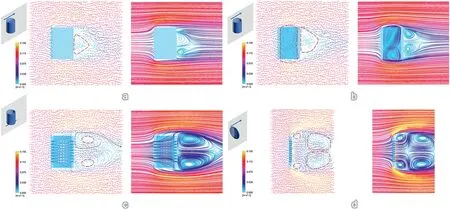
Fig.2.Fluid dynamics simulations (velocity vectors and streamlines) of fluid flow against (a) solid cylinder,(b) hollow cylinder,(c) porous hollow cylinder and(d)perforated discus shape,with catalysts aligned vertically toward flow direction.(c)and(d)represent the morphologies of amorphous and crystalline diatomites used in this work.Inset on top left corner displays the physical model used for simulation and the blue arrow indicates direction of fluid flow.The semi-transparent grey panel intersecting with the model shows the plane at which flow streamlines and velocity vectors are taken.For the plots of velocity vectors,the red circles with dashed lines mark out dead volume region,meaning fluid inside the region tend to circulate within the dashed circle area instead of joining the main streams.The green dashed line in Fig.2c depicts how the streams flowing through perforated walls helps in decreasing dead volume and keep it away from catalyst surfaces.Simulations were computed using Ansys fluent 2021 R2 with an air flow rate of 0.1 m/s.The units for all simulations were set from 0 to 0.15 m/s to allow direct comparison across models.All simulations are done assuming steady-state flow.
Moreover,the perforated hollow cylinder with macropores on the walls was expected to impose lower hindrance to the fluid flow.When they are used in packed bed reactors,we could expect smaller pressure drop across the catalyst bed.This is demonstrated by simulating the fluid flow through an array of catalysts with all three representative orientations discussed above(Fig.S5).Solid cylinder shape imposes the highest pressure drop of 0.127 Pa.With the use of hollow cylinder,there is a drastic decrease of pressure drop to 0.066 Pa.With the fluid able to flow through the macroporous walls,porous hollow cylinder shape gives the smallest pressure drop of 0.060 Pa.In addition,the pressure build-up has been simulated with individual catalyst shapes and orientations.By comparing the pressure contour and pressure vectors,we could see that the porous hollow cylinder configuration has the lowest pressure buildup near catalyst surfaces(Figs.S6–S8).
Based on our simulations,diatomite morphologies with macroporosity are clearly advantageous over non-porous shapes,for both batch and continous processes.Clearly,these morphology dependant merits cannot be preserved if diatomites are simply used as a silicon source to prepare mesoporous silica.With pores of a few nanometers in diameter and more than 1 μm in length for typical mesoporeous silica,on the other hand,incoming feed streams are nearly impossible to penetrate such narrow channels and the flow behaviour of such mesoporous silica samples is expected to follow the two non-porous structures illustrated in Figs.1 and 2.It is then desirable to explore surface reconstruction strategies to introduce mesoporosity without damaging the original morphology of diatomites.
In this section,we demonstrate how fluid dynamics are closely related to catalyst shape and porosity and the advantages of macroporous diatomite morphologies.As demonstrated earlier,the use of diatomite supports could benefit emerging applications of heterogeneous catalysis in continuous flow microreactors.Currently,industrial catalysts are manufactured into various shapes to accommodate different reaction and fluid conditions.At an industrial scale,packed bed reactor is one of the most used modular facilities for heterogeneous catalysis.To avoid channeling and flow maldistribution,the equivalent diameter of catalyst should be less than 1/20 of the bed diameter[44].For such packed bed reactors,prevailingly used catalysts with dimensions from mm to cm(Scheme 2a)are small enough to accommodate such requirements.In the context of packed bed microreactors,however,the reactor diameter is typically several mm or less.This requires the use of catalysts with ca.50 μm diameter to avoid undesirable channeling and flow maldistribution.When the catalyst size reduces from cm scale to μm scale,most of the industrial catalyst shapes cannot be reproduced in microreactors due to manufacturing limitations.To date,the catalysts used for packed bed microreactors are mostly limited to powders (e.g.,metal on carbon or alumina support) or resins (e.g.,functionalized polymeric resins)[45–48].In addition to shape limitations,these catalysts are also generally non-porous in nature and are less effective when compared with macroporous diatomite supports (as shown in Figs.1 and 2).

Scheme 2.Schematic illustrations of (a) sizes and shapes of typical catalysts used in chemical or petrochemical industry and (b) sizes and shapes of potential hierarchical catalysts based on diatomites.Natural diatom species have various shapes(e.g.,cylinders,disks,triangles,etc.Figure S9)and sizes,allowing the fabrication of different diatomite catalysts illustrated in this Figure.47 To accommodate the large variety of catalytic conditions,current industrial catalysts have been fabricated with different morphologies and dimensions.Owing to the manufacturing feasibilities and cost constraints,the typical dimensions of such industrial catalysts fall from mm to cm range.In this comparative depiction,diatomite-derived catalysts are able to not only reproduce the typical shapes of industrial catalysts,but also provide much more potential morphologies to better suit different reaction conditions.In addition,these diatomite-derived catalysts have a typical size range from 10 μm to 200 μm,which is several orders of magnitude smaller than the industrial catalysts,which may open up new opportunities for microfluidic catalysis.
Catalysts with size typically from 10 μm to 200 μm are ideal candidates for usage inside microreactors [49].In actual packed bed microreactors,there might be over 10^12 individual catalysts packed inside the column.Due to the limiation of computing resources,we are not able to produce quantitative simulation for actual fluid flow through the column.Nonetheless,based on our simulation with different orientations,it can be quanlitatively stated that macroporous morphology is preferred over non-porous materials with similar shape.In this regard,therefore,the surface modification and functionalization strategies presented in this work allow us to use diatomites as miniaturized industrial heterogeneous catalysts with different designed shapes (Scheme 2b).Naturally occurring diatom species were found to have cylindrical,spherical,disk-like and many more shapes (Fig.S9) [50,51].With the ability to modify both amorphous and crystalline diatomites,we could produce hierarchically porous silica supports to accommodate complex fluid dynamics inside microreactors[32,52].
In a longer term,the integration of such diatomite catalysts with microreactors are believed to be a way for promoting process intensification as well as transforming conventional batch process to continuous flow synthesis.Moreover,miniaturization of industrial catalysts inside microreactors allows better simulation of actual packed bed reactors used in industry,so that we could perform rapid catalyst material screening with more reliable results.It can also help in better optimization of reaction conditions and understanding reaction kinetics,which are crucial for scaling up of chemical processes.Potentially.various shapes of diatomite catalysts also enable topological optimization toward flow distribution inside the microreactors,which will lead to higher reaction rate[53,54].As the first step toward all these ultimate goals,nevertheless,in the following sections we will focus only on two important aspects of this proof-of-concept investigation: miniaturization of catalysts and workability of resultant catalysts in different types of heterogeneous catalysis,including several important reactions in both liquid-solid and gas-solid phases.
3.2.Synthetic protocol and surface reconstruction
Being an acidic oxide,the dissolution of silica with alkaline solution is a well-known process.Creation of hollow/mesoporous silica structures with controlled alkaline dissolution of solid silica templates has also been demonstrated in reported literatures [17,55].Because diatomites are mainly made of silica,we believe such controlled alkaline dissolution approach could be adopted for endowing mesoporosity within intrinsically macroporous diatomite structures.In this research,two distinct diatomites have been evaluated with one being largely amorphous and another one being highly crystalline in structure (revealed by PXRD in Section 3.4).By successfully introducing new mesoporosity to these two types of samples with alkaline assisted surface reconstruction techniques,we have illustrated the versatility of this synthetic architecture and its potential extension to a wide variety of other members of the diatomite family.
The amorphous diatomite sample,denoted asa-diatomite,was obtained from Mount Sylvia Pte.Ltd (Queensland,Australia) and used directly without further treatment.The diatomite sample consists both hollow cylinders (about 7 μm in outer diameter) and their broken parts(e.g.,curved planes).Macropores with diameter about 500 nm were distributed rather regularly with perpendicular orientation(Fig.3a and b and Fig.S10).The amorphous nature of this diatomite sample was confirmed with powdered X-ray diffraction (PXRD),which will be addressed in Section 3.4.Due to its less-rigid structure,a-diatomite is more vulnerable to alkaline dissolution treatment.Fora-diatomite,surface reconstruction to create new mesoporosity can be attained using one-step hydrothermal treatment(detailed reaction conditions stated in Experiment Section 2.2)with the addition of CTAB as structural directing agent (SDA).The product after the hydrothermal treatment was examined with TEM technique which reveals that the smooth surface of originala-diatomite sample has been transformed into a sponge-like rough surface with numerous open pores.More importantly,a thin over-layer of mesoporous silica(mSiO2)with uniform thickness of about 15 nm was observed(Fig.3c and d)while the pristine macropores were well preserved (Fig.S11).Such a resultant sample is denoted asa-diatomite/mSiO2.Under given reaction conditions,it is believed a dissolution-recondensation process has taken place during the hydrothermal treatment.Under the alkaline process environment,dissolution of naturala-diatomite first takes place,producing dissolved sodium silicate species.The silicate oligomers produced were then recondensed to silica in presence of CTA+ions [14,15].In the case of Fig.3c–d,the liquid-solid interface formed between CTA+ion and solution liquid could promote heterogeneous nucleation,resulting in the formation of SiO2/CTA+via condensation reaction.As reported in literature,the surface charge of diatomite appears negative in alkaline solutions[56].Thus,the newly added CTA+ions could adsorb onto the surface ofa-diatomite.Therefore,the new SiO2/CTA+formed via condensation will naturally been coated to the surface of pristinea-diatomite skeleton.Subsequent removal of trapped CTA+ions via calcination then gives rise to the desired mesoporous SiO2structure.The thickness of thismSiO2coating layer can be adjusted by controlling the concentration of CTAB.A comparative experiment with a higher CTAB concentration has resulted in the formation of thickermSiO2shell(Fig.S12).
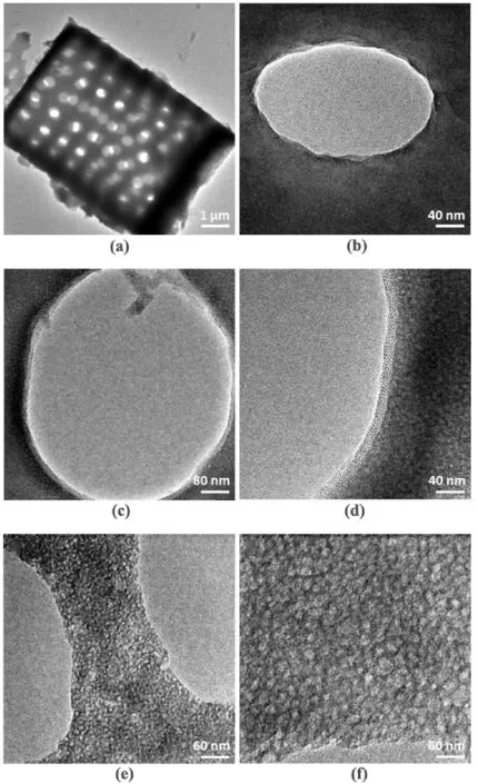
Fig.3.Representative TEM images of(a,b)natural a-diatomite sample,(c,d)a-diatomite/mSiO2 sample after the formation of mesoporous silica layer and(e,f)sadiatomite sample in which the natural diatomite was treated in alkaline solution without presence of surfactant CTAB.
In a typical synthesis,50 mg of naturala-diatomite was used to produce 41 mg ofa-diatomite/mSiO2,achieving a yield of 82%.The weight loss of sample during solution was expected to be the result from silica dissolution.The products from this sample dissolution,namely sodium silicates (e.g.,in the form of Na2SiO3etc.),were soluble in alkaline solution.Under given reaction conditions,however,the silicate species released from dissolution were not completely converted to themSiO2coating layer.The remaining sodium silicate species in solution could be separated conveniently from the solida-diatomite@mSiO2product after centrifugation and repeated washing.
To better understand the role ofa-diatomite as silica source,another experiment was conducted using onlya-diatomite and dilute NaOH aqueous solution for hydrothermal treatment (Experiment Section 2.3).In this case,the obtained sample has a sponge-like texture(denoted assadiatomite,Fig.3e and f)with many open pores.Without the presence of CTAB,however,there is no sign ofmSiO2formation.
In this approach,the critical parameter for controlling desired hierarchical structure is the alkaline concentration in solution.On the one hand,the solution must have sufficient basicity to partially dissolveadiatomite sample to release silicate species for subsequent condensation process,allowinga-diatomite to be used as a silica source.On the other hand,the integrity ofa-diatomite sample and its macroporosity would be demolished if the solution becomes too basic,eventually leads to complete dissolution ofa-diatomite sample.This has been demonstrated with a control experiment using higher NaOH concentration (Fig.S13).In this case,it is seen that the original morphology and macroporosity of the diatomite have been largely destroyed under the more basic reaction environment.
Unlike amorphous diatomite samples,crystalline diatomite(denoted asc-diatomite)has a rigid structure and is more inert toward the alkaline dissolution.This diatomite sample has a discus-like shape withca.30 μm in diameter andca.10 μm in thickness.The macropores withca.150 nm in diameter have also distributed in perpendicular direction(Fig.4a to c).When treated with similar hydrothermal conditions like thea-diatomite sample,no obvious silica dissolution was observed.Thus,a stronger alkaline environment was thought to be able to dissolvec-diatomite.Nevertheless,this sample has presented a dilemma in choosing reaction parameters.On the one hand,in making use ofc-diatomite as a silica source,an extremely basic solution environment seems to be required.On the other hand,the growth ofmSiO2using silicate species released fromc-diatomite dissolution is a slow process,in which the reaction time might be long enough for the basic solution to break the structural integrity ofc-diatomite.As such,it is unlikely to grow and adheremSiO2overcoat toc-diatomite macropores in a single step.Therefore,a two-step hydrothermal process under different pH environments was developed to reconstruct the surfaces of this crystalline sample and to create new mesoporosity (Experiment Section 2.4).

Fig.4.Representative SEM and TEM images of (a–c) natural c-diatomite sample,(d–f) c-diatomite sample after first pre-treatment step and (g–i) c-diatomite/mSiO2 hierarchically porous sample after second hydrothermal treatment.
First,c-diatomite sample was pre-treated hydrothermally in a much stronger alkaline solution with 1.0 M NaOH solution for 30 min.This step was designed to partially transform highly stable crystalline SiO2to less rigid amorphous state,which enables the sample for subsequent modifications.By treating the crystalline sample for a short period of time,the structural integrity is not compromised.Seen from TEM images of the sample after first hydrothermal treatment,the smoothc-diatomite surface has become much rougher,with amorphous silica species present across the sample (Fig.4d to f).The same dissolution-recondensation process asa-diatomite was believed to occur on the surfaces ofc-diatomite sample.Without the presence of SDA,however,the as-formed amorphous SiO2was irregularly shaped aggregates without any mesoporosity.
As the first step was aimed to crack or loosen the rigid structure ofcdiatomite,the solution was purposely set to be highly basic.Upon completion of the hydrothermal treatment for 30 min,the resulting solution pH was around 14.Further extension of this pre-treatment time leads to destruction of diatomite morphology and thus macroporosity(Fig.S14).The basic environment indeed had helped to partially convert crystalline SiO2to amorphous form.However,it was too basic for subsequent formation ofmSiO2,which occurred over a longer duration of 4 h under hydrothermal conditions.In fact,the pre-treated solution has been added with CTAB and directly subjected to a second hydrothermal treatment at 100°C for 4 h.This has resulted in destruction of thecdiatomite morphology without formation ofmSiO2(Fig.S15).Thus,the pH value of the solution was lowered to 10 by H2SO4solution prior to the second hydrothermal treatment.In this case,formation ofmSiO2was achieved while the original morphology and macroporosity ofc-diatomite were kept intact(Fig.4g to i);the product after the second treatment was denoted asc-diatomite/mSiO2.As seen from TEM images,the asformedmSiO2was distributed on the outer surface of thec-diatomite backbones and this can be attributed to a reconstructional result of the interaction between CTA+ions and amorphous silica or adsorbed siliceous species (formed from the pre-treatment) on thec-diatomite surfaces.As investigated for amorphous sample,positively charged CTA+ions could be adsorbed onto negatively chargedc-diatomite surfaces due to electrostatic interaction[56].As surface amorphous silica undergoes a new round of dissolution-condensation during the second hydrothermal treatment,the CTA+ions formed rod-like micelles as in the synthesis of MCM-41 which also act as heterogeneous nucleation sites to promote preferential condensation at the CTA+/liquid interface.As a result,formation ofmSiO2was restricted to the surface of pristinec-diatomite sample.As this crystalline diatomite sample is bulkier in size and less porous as compared to the amorphous one,it is important to rotate the autoclaves during both pre-treatment and mesoporous silica formation stages,to ensure the homogeneity of products(Figs.S16 and S17).There is no free-standing mesoporous silica found in solution for both amorphous and crystalline samples.This indicates that the CTA+ions mainly deposit on the diatomite surface,allowing the controlled formation of mesoporous silica shells.
It is believed that the surface reconstruction and formation of mesopores will not alter the fluid flow patterns illustrated in Section 3.1.For both amorphous and crystalline diatomites,the catalyst size and macropore diameter are far greater than the thickness and channel diameter of newly formed mesopores.The feed streams are likely to enter the mesoporous channels via diffusion,without significant change in fluid dynamics.Thus,the advantages of diatomites’macroporous morphology in reducing dead volume,avoiding mass transfer limitation and lowering pressure drop can be maintained after this modification.
3.3.Surface modification and catalytic functionalization
Upon successful establishment of the hierarchical meso-macro porosity in both amorphous and crystalline diatomites via surface reconstruction,in this section,surface modification and catalytic functionalization were further pursued to illustrate their capability as catalyst supports.In particular,a surface grafted method was used to chemically modify sample surfaces,allowing the deposition of noble metals(Experiment Section 2.5) [55,57].By overnight refluxing the samples with APTMS,functional groups of terminal amine (-CH2CH2CH2NH2)have been grafted onto channel pores ofmSiO2.Taking the deposition of Pd NPs ontoa-diatomite/mSiO2as an example,the surface grafted–NH2groups were able to attract and fix the metal ions within the porous channels ofmSiO2.The mixture was then washed to remove any free metal precursors in solution.Subsequent calcination in H2atmosphere has led to the reduction of–NH2fixed metal ions,forming small Pd NPs with uniform distribution across themSiO2porous channels (named asa-diatomite/mSiO2@Pd,Fig.5a).The successful deposition of Pd within mesoporous channels was confirmed on the basis of TEM images and the homogeneous distribution of Pd element across the diatomite support(revealed by elemental mappings using EDX analysis,Fig.5b).When subjected to Suzuki coupling reaction (detailed discussion in Section 3.5.1),thisa-diatomite/mSiO2@Pd sample has also shown minimum Pd aggregation as compared to supportedsa-diatomite@Pd sample,implying the confinement of Pd within mesoporous channels.The same procedure also holds for crystallinec-diatomite/mSiO2sample and can be extended to other noble metals like Pt and Ag (Fig.5c to h and Experiment Section 2.7).This surface grafting method relies on the silane chemistry to fix the–NH2amino groups on the surface of silica matrix and is versatile enough to be extended to most supports made of silica.Not limited to thea-diatomite/mSiO2andc-diatomite/mSiO2,thesa-diatomite sample with spongy surface and originalc-diatomite sample were also able to be used as metal supports via the same surface grafting method (Fig.S18 and Experiment Section 2.6,2.7).The catalytic advantage,however,of having the mesoporous silica will be illustrated in a later section for Suzuki coupling reaction and CO2hydrogenation reaction.

Fig.5.Representative TEM images and EDX mappings of (a,b) a-diatomite/mSiO2@Pd,(c,d) c-diatomite/mSiO2@Pd,(e,f) c-diatomite/mSiO2@Pt,and (g,h) cdiatomite/mSiO2@Ag sample.
In addition to mesoporous SiO2formation as demonstrated above,another possible way to introduce hierarchical porosity is to directly endow diatomite samples with micro or mesoporous coatings,generating even more complex integrated catalysts with tailored functionalities.In this work,a synthetic approach has been developed to coat ZIF-8 overlayer (with micropores) onto thesa-diatomite@Pd sample (Fig.6a to c and Experiment Section 2.8).It is seen that numerous ZIF-8 crystals were formed on the surface ofsa-diatomite@Pd sample.The elemental distribution of N could originate from both the–NH2group used for fixing of Pd and the organic linker (2-MeIM) to Zn cation in ZIF-8 phase.The elemental distribution of Zn better confirms the formation of ZIF-8 overlayer as it can only originate from newly formed ZIF-8 crystals(EDX mappings of N and Zn,Fig.6d).The pre-anchored Pd NPs were not affected by the latter process(i.e.,surface coating of ZIF-8).As there were no alkalis used in this reaction,sa-diatomite@Pd sample was first modified by mixing with PSS aqueous solution,to produce negatively charged surfaces.Metal cations (Zn2+) were then added to the solution and adsorbed onto the PSS-modified surfaces via electrostatic interaction.Finally,organic linker 2-MeIM was introduced to the solution and the coordination between 2-MeIM and Zn2+leads to the formation of ZIF-8 overcoat.To realize this synthetic protocol,a two-step ZIF-8 formation at different temperatures was devised to avoid undesired formation of free-standing ZIF-8 crystals in solution.At room temperature,ZIF-8 nuclei could form at solid-liquid interface (i.e.,heterogeneous nucleation at interface betweensa-diatomite@Pd sample and solvent liquid)or in the solution (i.e.,spontaneous homogeneous nucleation in liquid phase).While the heterogeneous nucleation would lead to the formation of ZIF-8 coating shell to thesa-diatomite@Pd sample,the undesired homogeneous nucleation process could result in the formation of free standing ZIF-8 crystals(Fig.S19).Based on the classical nucleation theory,the energy barrier for heterogenous nucleation can be expressed as ΔGhetero=f(θ)ΔGhomo,where f(θ)=and θ stands for the degree of contact angle.When the reaction temperature was reduced to 0°C by placing mixture solution in ice/water mixed bath,the rate of homogeneous nucleation would be reduced significantly due to high energy barrier.Owning to the f(θ) factor,energy barrier for heterogeneous nucleation at this temperature is much lower.Besides,our rough surfaces of mSiO2will make heterogeneous nucleation even more preferable in reality,as the above theory is based on flat solid surfaces.Thus,ZIF-8 seeds (nuclei/clusters) could still form at liquid/diatomite interface[58,59].After reacting for 1 h at 0°C,it is believed the surface ofsa-diatomite@Pd sample had been evenly covered by tiny ZIF-8 clusters(or nuclei).Therefore,the sample was able to provide ZIF-8 seeds for the subsequent coating shell growth in desired thickness by further reaction with additional 2-MeIM at room temperature.In this way,no freestanding crystal cubes or other common polyhedral forms of ZIF-8 were found in solution with the second addition of 2-MeIM at room temperature.The catalytic advantage of having this ZIF-8 shell will be further demonstrated in later section for selective hydrogenation reaction of alkenes.
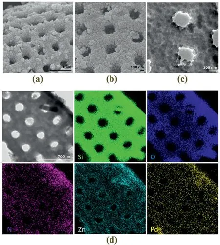
Fig.6.Representative (a,b) SEM,(c) TEM and (d) scanning TEM image and corresponding EDX mappings of sa-diatomite@Pd@ZIF-8 sample.
3.4.Creation of hierarchical macro-meso-micro porosity
Powder X-ray diffraction (PXRD) was used to evaluate structural properties of diatomite samples.XRD patterns of two different diatomite samples investigated in this work were distinctively different.First,theadiatomite sample has shown a broad 2θ peak around 21°,which is a characteristic peak of amorphous silica(Fig.7a)[16,60].The only sharp peak observed at 26.6°corresponds to (101) reflection of quartz phase(Fig.7a,JCPDS No.11–0252).The coexistence of broad peak and sharp peak indicates thea-diatomite sample is a mixture of amorphous and crystalline silica.However,the fact that only the most significant (101)peak of the crystalline silica was observed implies that the sample was mainly amorphous silica,with the presence of crystalline sample in a small quantity only.As discussed in the sample preparation steps,this mainly amorphous sample was more vulnerable to alkaline dissolution and surface reconstruction was realized using one-pot synthesis (Experiment Section 2.2).In contrast,the XRD pattern ofc-diatomite sample has mostly sharp peaks corresponding to highly crystalline SiO2structure(cristobalite,JCPDS No.27–0605) with almost negligible board peak around 21°.Such XRD pattern indicates that this sample was mainly in the phase of cristobalite,while the presence of amorphous phase was too little to cause any impact.Upon formation of mesoporous silica via the two-step hydrothermal treatment,the as-formedc-diatomite/mSiO2sample has displayed similar XRD pattern to the originalc-diatomite sample (Fig.S20).Such observation further assures that the given synthetic condition is mild enough for retaining the original macroporosity and morphology.Also,the amount of mesoporous silica formed via surface reconstruction was much less as compared to the retained macroporous diatomite backbones.XRD pattern has also been used to confirm the formation of ZIF-8 coating layer withsa-diatomite@Pd@ZIF-8 sample.The XRD pattern of this coated sample displays strong ZIF-8 diffractions after the deposition of surface ZIF-8 (Fig.7b)[61],as confirmed by the simulated result of this MOF.

Fig.7.PXRD patterns of (a) original a-diatomite and c-diatomite samples,and (b) sa-diatomite@Pd@ZIF-8 sample and simulated ZIF-8.
The pore structure and texture properties of samples before and after surface reconstruction have been examined with BET isotherms(Fig.8).For botha-diatomite andc-diatomite samples,type II N2-sorption isotherms were observed with original samples,corresponding to the physisorption of N2gas on macroporous adsorbents(Fig.8a and b)[62].After the formation ofmSiO2,their sorption-isotherms have changed to type IV,confirming the existence of mesopores [62].Thea-diatomite/mSiO2sample has experienced an increase in specific surface area from 17.5 to 220.6 m2g-1after themSiO2coating.Being bulkier in size with smaller pores,the pristinec-diatomite sample has a much lower surface to volume ratio and the BET surface area was measured to be only 1.7 m2g-1.After the two-step treatment to introduce mesoporosity,nonetheless,the BET specific surface area increased about four times to 8.4 m2g-1.For both amorphous and crystalline samples,N2-sorption isotherms have shown a similar H3 type hysteresis loop after mesoporous silica formation[62],also noting the existence of pristine macropores in the pore network.This result further validates that the original diatomite morphology and corresponding macroporosity were well preserved with the above surface reconstruction approaches.
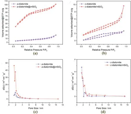
Fig.8.N2-isotherm before and after the formation of mesoporous silica for (a) a-diatomite and (b) c-diatomite samples;pore-size distribution before and after the formation of mesoporous silica for (c) a-diatomite and (d) c-diatomite samples.
Based on high-resolution TEM investigations,detailed examination on the catalysts was carried out to understand the texture properties of mesopores formed by these two different approaches.Fora-diatomite/mSiO2sample,there is no clear aggregate boundaries and there are randomly distributed channels without long-range ordering.This implies themSiO2formed is also amorphous in nature (Scheme 1a and Fig.9a and b).Forc-diatomite/mSiO2sample formed via the two-step route,the mesoporous silica formed has shown clear 1D-channels(Scheme 1b and Fig.9c and d).In addition,boundaries between different mesoporous silica aggregates have been revealed.The pore size distribution agrees well with the observed textures of the two samples.Thea-diatomite/mSiO2sample has only one major peak around 2 nm which is characteristic to the SDA used during synthesis(Fig.8c).Thec-diatomite/mSiO2has shown additional peaks greater than 2 nm,which is believed to be the spacing between different mesoporous silica aggregates (Fig.8d).We believe that differences in synthetic procedure and starting material are responsible for the observed texture differences.For amorphous diatomite,the surface modification was achieved using one-step hydrothermal treatment.In this case,the silica source was directly hydrolyzed by alkaline etching of diatomite surfaces.For crystalline diatomite,surface modification was achieved using two-step hydrothermal treatment.Etching of diatomite surface was carried out at the first step,producing non-porous silica aggregates.At the second step,this non-porous silica aggregate was hydrolyzed and recondensed in presence of CTA+to produce mesoporous silica shell.We propose it is the difference in starting precursor responsible for the different pore structures observed with amorphous and crystalline diatomites.

Fig.9.Representative TEM images at high resolution to reveal the texture and pore structure of mesoporous silica formed with (a,b) a-diatomite and (c,d) cdiatomite samples.
The texture properties ofsa-diatomite sample have also been evaluated.Based on the sorption isotherm and pore size distribution(Fig.S21),there is no formation of mesoporous channels for this spongy sample,due to lack of SDA during the alkaline treatment.
3.5.Heterogeneous catalysis with miniaturized catalysts
In this section,we would like to use following model reactions to illustrate the catalytic performance of our hierarchically porous diatomite catalysts synthesized from surface reconstruction,modification,and functionalization.Model reactions representing both aspects of heterogeneous catalysis,namely solid-liquid and solid-gas systems,were employed to test the diatomite derived catalysts.In Section 3.1,we have concluded that diatomite morphology is advantageous for both batch and continuous reactions.Thus,our hierarchically porous diatomite catalysts were tested in both batch and continuous set-up.In the liquid-phase reaction(Experiment Section 2.9,2.10),it has been shown the creation of mesopores via surface reconstruction could significantly enhance catalyst stability while preserving the macroporosity ensures the increase in diffusional barrier is minimum.In the next model reaction,reactant selectivity was achieved by creating micro-meso-macro hierarchical porosity to the amorphous diatomite sample.In this reaction,it is our intention to prove that the superior catalytic properties from complex and advanced silica catalysts synthesized with expensive precursors can be reproduced with diatomite derived samples.Lastly,a gas phase model reaction was adopted.We have further confirmed the robustness of the diatomite catalysts toward various reaction conditions.More interestingly,enhanced catalytic activity has been achieved since the creation of mesoporosity leads to longer retention time of reactant substrates in catalyst phase.
3.5.1.Liquid-phase Suzuki coupling reaction
Suzuki-Miyaura coupling reaction (referred as Suzuki reaction) is arguably one of the most important reactions in organic synthesis and has been widely adopted in pharmaceuticals and fine chemistry [63–73].Originally discovered as homogeneous reaction with Pd ions,the utilization of supported Pd NPs for Suzuki reaction has also gained much interest in past two decades.By heterogenizing the catalyst,we could effectively reduce the use of expensive and hazardous organic coupling compounds and provide easy routes for recycle and reuse of catalysts [74–79].In particular,mesoporous silica has been identified as one of the most suitable supports for such reactions with several advantages [12,80–83].Firstly,the uniform mesoporous channels are tailorable to accommodate many reactants used in Suzuki reaction.Secondly,the Pd NPs confined within the mesoporous silica matrix are unlikely to grow by direct coalescence.Thirdly,the diffusion path of mesoporous silica matrix could help to reduce Pd leaching to the solution and Pd aggregation via Ostwald ripening.All in all,mesoporous silica supported Pd NPs could enhance the reaction stability of catalysts when subjected to Suzuki reaction.
In this work,we would like to prove that oura-diatomite/mSiO2@Pd andc-diatomite/mSiO2@Pd samples with hierarchical porosity could achieve similar catalytic performance for Suzuki reaction comparing to literature reports with hollow/hierarchical silica supports synthesized from conventional silica sources.By replacing mesoporous silica synthesized from organic precursors with naturally available diatomites,this would present great opportunities in both achieving greener chemistry and producing catalysts at a much lower cost.Comparing with full conversion of diatomite sample to mesoporous silica matrix where longer diffusion path was required for metal NPs loaded near center of the support [22,23,25,42],our diatomite samples with hierarchical pore structures obtained from the surface reconstruction were believed to yield higher diffusion rates [11].The macropores ensures rapid mass transfer and short diffusion paths for the reactants to interact with loaded metal NPs,while the mesopores could increase catalyst stability similar to MCM-41 like mesoporous silica supports.
The reaction was carried out with a round bottom flask heated to 80°C in an oil bath.As illustrated in Table 1,botha-diatomite/mSiO2@Pd andc-diatomite/mSiO2@Pd catalysts are highly active for the Suzuki reaction between different aryl halides and phenyl boronic acid.For both catalysts,more than 80% conversion can be achieved after a reaction time of 15 min (Table 1,entries 1–10).Taking the coupling of iodobenzene and phenyl boronic acid as an example,we found that 91.1%aryl halide conversion was achieved witha-diatomite@mSiO2/Pd sample after reacting for 15 min (Table 1,entry 1).As for thec-diatomite/mSiO2@Pd sample,an even higher conversion of 91.6%was seen using the same iodobenzene as an aryl halide (Table 1,entry 7).For both catalysts,the measured activity was comparable to literature reports of similar immobilized Pd catalysts with various supports(Table S1).

Table 1Suzuki cross-coupling reactions catalyzed by Pd functionalized diatomite catalysts.
To understand the impact of having thismSiO2layer,sa-diatomite@Pd sample was prepared in which Pd NPs were directly deposited onto the macroporous diatomite support(Experiment Section 2.6).23.4 mg ofsa-diatomite@Pd sample was used to ensure the same amount of Pd was used as compared to 20 mg ofa-diatomite@mSiO2/Pd.The conversion rate and TOF were slightly higher in this case(Table 1,entries 11–16).Similar reactant conversion has been observed for samples with and without the mesoporous silica coating shell.Such an observation suggests that the hierarchically porousa-diatomite/mSiO2@Pd andcdiatomite/mSiO2@Pd samples do not create additional mass diffusion barriers to limit the reaction rate under the given conditions.
Repeated runs with iodobenzene and phenyl boronic acid were carried out in which spent catalyst was separated from reaction solution via centrifugation,dried in vacuum oven and immediately subjected to next reaction run.The advantage of havingmSiO2layer over the baresadiatomite@Pd sample was clearly illustrated when the catalysts were recycled for multiple runs(Fig.10).For botha-diatomite/mSiO2@Pd andc-diatomite/mSiO2@Pd catalysts,the reactant conversion was stable for up to 10 runs with only a slight decrease.Both samples have shown high stability in given reaction conditions.However,thesa-diatomite@Pd sample withoutmSiO2shell has shown drastic drop in conversion when subjected to repeated runs.After cycling for 10 times,the conversion of iodobenzene was dropped from 99.3% to 95.6% fora-diatomite/mSiO2@Pd sample,and 100% to 93.4% forc-diatomite/mSiO2@Pd sample.For thesa-diatomite@Pd,however,the iodobenzen conversion decreased from 100%to 45.3%after 10 reaction cycles.

Fig.10.Recyclability test of a-diatomite/mSiO2@Pd, c-diatomite/mSiO2@Pd and sa-diatomite@Pd samples for Suzuki coupling reaction.After 10 repeated runs,both samples with mesoporous silica have shown minimum reduction in conversion while the reactant conversion for sa-diatomite@Pd drops significantly.
In order to understand the difference in stability,spent catalysts were examined with TEM.On the basis of TEM observations (Fig.5a and Fig.S18),the particle size distributions of fresha-diatomite/mSiO2@Pd andsa-diatomite@Pd samples were plotted(Fig.S22).After 10 repeated cycles,the Pd NPs ofa-diatomite/mSiO2@Pd sample was still wellconfined with a marginal growth in particle size from 1.6 nm to 1.8 nm(Fig.S23a).The catalyst morphology and mesoporous silica shell are both well maintained after 10 repeated runs.This indicates that theadiatomite/mSiO2@Pd sample is rather stable under given reaction conditions.Forsa-diatomite@Pd sample,however,metallic Pd aggregation was clearly observed,where the Pd particle size grows from 1.9 nm to 13.3 nm with a much wider range of variation (Fig.S23b).Apparently,the aggregation of Pd NPs also leads to the decrease in active sites and thus the deactivation of catalyst as we have seen from the recyclability plot(Fig.10).The difference in texture properties,namely the presence of mesoporous channels,is believed to be the reason responsible for the difference in Pd aggregation during given reaction conditions.
It has been proven recently that leached Pd species are the sole genuine catalytic intermediate in the cross-coupling reaction[79].That means the Pd NPs would leach into solution to produce the active intermediate species and redeposit back when the reaction was complete[79,84].It is apparent that the growth of Pd NPs followed Ostwald ripening process when the leached Pd species redeposited back to the support after the reaction.Without the confinement effect ofmSiO2overcoat,Pd NPs would grow unconstrainedly into larger crystals as the growth is thermodynamically favored,whereas with the provided spatial confinement ofmSiO2,the growth of Pd NPs was restricted when they were distributed inside themSiO2channels.
Ostwald ripening growth is the process where smaller nanoparticles dissolve and redeposit onto larger nanoparticles.During Suzuki reaction,Pd species were dissolved and released to solution,making crystal growth via Ostwald ripening relatively easier.When Pd NPs were deposited onto support surfaces,the dissolved species can travel a short distance to be deposited onto nearby larger NPs.This is the case forsadiatomite@Pd catalyst.Without presence of mesoporous channels as revealed from N2-sorption analysis (Fig.S21),the growth of Pd NPs during reaction was unrestricted and resulting in the large aggregates seen from the spent catalyst(Fig.S23).For botha-diatomite@mSiO2/Pd andc-diatomite@mSiO2/Pd catalysts,however,Pd NPs were located within mesoporous channels of themSiO2overcoat (formed via surface reconstruction,Experiment Section 2.5,2.7).With the confinement of Pd nanoparticles within mesoporous channels,the dissolved Pd species must travel a much longer distance along the narrow mesoporous channel,before being deposited onto larger NPs.Thus,furthermore,the particle growth via Ostwald ripening will also become much harder in presence of mesopore confinement,avoiding the likelihood of rapid growth of Pd nanoparticles.Other possible mechanisms(such as direct metal fusion or aggregation among the Pd nanoparticles) can be ruled out,as our reaction temperature was low.In addition,the confinement of Pd within mesoporous channels serves as a physical barrier to prevent the direct contact of individual nanoparticles.
3.5.2.Liquid-phase selective hydrogenation of alkenes
While pursuing the goal of greener chemistry,there has been an increasing trend for product/reactant selective reactions using specifically tailored multifunctional catalysts.Among the reports in literature,selective reactant diffusivity has been one of the most adopted approaches to achieve desired reaction selectivity [55,79].By coating the active catalyst with a screening shell,only desired reactants could diffuse through and get converted.The selective shell diffusivity could originate from both physical size-sieving effect and chemical interaction with the shell material.In this work,we have attempted to create micro-meso-macro hierarchical porosity to the amorphous diatomite sample(Experiment Section 2.8),with microporous ZIF-8 coating shell as a diffusional barrier for the selective hydrogenation of styrene over cyclohexene.
The reaction was carried out in a round bottom flask heated to 35°C with an oil bath.H2gas was continuously bubbled into the mixture as a hydrogen source.To understand if selective hydrogenation can be achieved withsa-diatomite@Pd@ZIF-8 structure,we need to first understand the intrinsic reactivity of Pd toward these two hydrogenation reactions.Thus,reference reactions were carried out usingsa-diatomite@Pd as the catalyst.Without the presence of ZIF-8 layer,similar reactivity was observed for hydrogenation of styrene and cyclohexene.After reacting for 60 min,both cyclohexene and styrene have been fully hydrogenated to cyclohexane and ethylbenzene,respectively.Under the given conditions,only the C––C double bond will be hydrogenated,and the benzene ring remains inactive.To further prove Pd has negligible bias for the hydrogenation of styrene and cyclohexene,conversions of reactants at different time intervals were plotted for both reactants(Fig.11a).From the time dependent plot,it is clearly illustrated that the hydrogenation of cyclohexene and styrene occurred in similar rates.

Fig.11.(a)Time-dependent conversion of styrene and cyclohexene when subjected to hydrogenation reaction using sa-diatomite@Pd sample;and(b)conversion of styrene and cyclohexene after coating sa-diatomite@Pd with ZIF-8 shell.While the conversion of styrene reduced from 100%to 75.9%,the conversion of cyclohexene reduced drastically to 7.8%.This proves the successful application of ZIF-8 layer as selective diffusional barrier.
Knowing the intrinsic activity of Pd for these two hydrogenation reactions,we then proceed to test thesa-diatomite@Pd@ZIF-8 sample with the additional ZIF-8 coating.While 16 mg ofsa-diatomite@Pd sample was used in the reference tests,20 mg ofsa-diatomite@Pd@ZIF-8 sample was used to ensure the same amount of Pd was loaded in both catalysts.In this case,a slight drop in styrene conversion from 100%to 75.9%was observed after reacting for 60 min under the same conditions(Fig.11b).Such a decrease in reactivity was expected as the microporous channels of ZIF-8 layer inevitably serves as diffusional barrier and the styrene molecules must diffuse through the narrow channels to get interacted with the imbedded Pd NPs.Such mass diffusion limitation then leads to the observed drop in reactivity.More importantly,the conversion of cyclohexene has dropped from 98.6% to 7.8%.These tests have shown that ZIF-8 layer serves as a selective diffusional barrier favoring styrene over cyclohexene.Unlike many other cases where diffusional selectivity was a result of different molecule size and physical sieving,both styrene(8.5×6.0×4.0 Å3)and cyclohexene(6.3×5.7×4.5 Å3)are similar in size and chemical interaction was believed to be the reason for this selective diffusion [79].Such a diffusional selectivity has been observed with other catalysts with ZIF-8 shells,and it is believed that the ZIF-8 channels could act as stimuli-responsive smart shell and the π-π stacking interaction between styrene and the aromatic framework of ZIF-8 serves as the external stimulation [55,85].This external stimulation from styrene was able to trigger the gate-opening of flexible MOF framework to allow the diffusion of styrene through the microporous channels and interact with the Pd NPs underneath the ZIF-8 shell.Cyclohexene,on the other hand,do not possess such π-π stacking from phenyl ring and cannot trigger the gate opening mechanism.Thus,cyclohexene can hardly diffuse through and the much lower conversion rate was seen for the sample after ZIF-8 coating.
3.5.3.Gas-phase hydrogenation of CO2 to CO
In addition to the above two liquid-phase reactions carried out in batch reactors,we have also carried out a gas-phase reaction using continuous flow packed bed reactor to further illustrate the versatility and robustness of these diatomite-based catalysts.In this selected model reaction,c-diatomite/mSiO2@Pt catalyst was used for the hydrogenation of CO2to CO.The reaction was conducted at atmospheric pressure and temperature ranges from 200 to 400°C.Under such reaction conditions,thisc-diatomite/mSiO2@Pt catalyst has also exhibited good activity and selectivity with CO being the sole reaction product.
By controlling the concentration of H2PtCl6aqueous solution used during synthesis from 0.5 mM to 3.0 mM,a series ofc-diatomite/mSiO2@Pt catalysts with different Pt loadings were prepared.The resulting samples were denoted asc-diatomite/mSiO2@Pt-0.5 (e.g.,the concentration of H2PtCl6aqueous solution used for Pt loading was 0.5 mM,Section 2.7),c-diatomite/mSiO2@Pt-1.0,c-diatomite/mSiO2@Pt-1.5,c-diatomite/mSiO2@Pt-2.0,andc-diatomite/mSiO2@Pt-3.0.On the basis of ICP-OES analysis,the Pt loading was measured to be 0.9 wt %,1.8 wt%,2.8 wt%,4.0 wt%and 4.4 wt%,respectively.These catalysts were subjected to CO2hydrogenation reaction with a feed stream of CO2/H2/N2=24%/72%/4%,flowing at 20 mL⋅min-1(Fig.12a).In general,the CO2conversion increases with increasing Pt loading as there are more catalytically active sites available.When Pt loading increases from 4.0 wt%to 4.4 wt%,the CO2conversion was almost identical.Further increase loading probably leads to larger Pt aggregates and the increase in active sites is negligible.These Pt loaded samples have shown similar reactivity when compared with literature values(Table S2).

Fig.12.(a)Temperature dependent CO2 conversion for CO2 hydrogenation to CO with various Pt loaded c-diatomite or c-diatomite/mSiO2 samples;and(b)catalyst stability test of c-diatomite/mSiO2@Pt samples for 24 h on stream.
The advantage of having hierarchical porosity for this gas phase reaction was further illustrated with a comparative experiment carried out with barec-diatomite@Pt sample(Experiment Section 2.7)in which the support is unmodifiedc-diatomite.Having a Pt loading of 1.5 wt%,this sample without mesoporous silica matrix has shown significantly lower CO2conversion when compared with those hierarchically porous samples (Fig.12a).As illustrated with BET isotherm (Fig.8b),thec-diatomite/mSiO2@Pt sample has increased specific surface area and ordered mesoporous channels.All these could lead to longer residence time of reactant gas and higher CO2conversion was obtained[86].
As reported in Fig.12b,thec-diatomite/mSiO2@Pt samples were subjected to 24 h on stream test to evaluate their stability.Stable CO2conversion similar to literature Pt catalyst has been identified,proving these catalysts are quite stable under given reaction conditions[86].
4.Conclusions
We presented the surface reconstruction,modification,and functionalization of naturally available diatomites to produce hierarchically porous silica supports and corresponding catalysts.Two different surface reconstruction techniques have been devised for amorphous and crystalline samples,respectively.For amorphous diatomite sample,a one-pot dissolution-condensation process has been developed in which NaOH solution was used to provide alkaline environment to partially dissolve the diatomite precursor and CTA+ions were used as structural directing agent to facilitate the condensation process to produce mesoporous silica matrix.Synthetic parameters were optimized to form mesoporous silica layer on surfaces of original diatomite sample,without compromising its shape and macroporosity.For crystalline diatomite sample in which a much higher basicity is required to dissolve the sample,a two-step approach has been presented.The first pre-treatment step dissolves crystalline diatomite with more concentrated NaOH solution and allows the dissolved silica species to recondense to amorphous silica without presence of SDA.The next step was carried out at lower pH value in which the amorphous silica was then transformed to MCM-41 like mesoporous silica matrix.
The two hierarchically porous diatomite supports were then chemically modified and functionalized with noble metal nanoparticles.The Pd loaded samples,a-diatomite/mSiO2@Pd andc-diatomite/mSiO2@Pd,have been tested for liquid-phase Suzuki reaction.Comparing withsadiatomite@Pd sample without mesoporous silica,similar reactivity was achieved with all three samples,illustrating the hierarchical porosity has led to negligible diffusional barrier and efficient mass transfer from bulk solution to the active Pd NPs has been achieved.More importantly,samples with mesoporous silica have shown much enhanced stability with minimal deactivation over 10 repeated runs.On the other hand,sadiatomite@Pd sample has shown continuous deactivation after each run and the reactant conversion drops from 100%to 45.3%after recycling for 10 times.To further illustrate the robustness of these diatomite supports,gas-phase CO2hydrogenation reaction was carried out withc-diatomite/mSiO2@Pt sample.The catalyst has shown good CO2conversion with CO being the only product and the performance was stable for up to 24 h on stream test.
With the rapid advances in nanomaterial synthesis,there have been growing research interests to pursue integrated nanocatalysts with increasing morphological and compositional complexity.In this work,we have demonstrated how fluid flow is closely related to catalyst shape and porosity with fluid dynamics simulations.While silica with sophisticated structures has been recognized to be superior in many applications,in this work,the synthesis of complex catalyst support with hierarchical porosity from diatomite precursors have shown the potential of reproducing these advanced catalysts using naturally available silica sources.Not only presenting a much greener and environmental-friendly approach,the adoption of natural silica source in the present study could also significantly reduce the production cost for possible industrial scale applications.Moreover,the macroporous morphology of diatomites have been proven to reduce dead volume in reactor and improve catalytic performance for both batch and continuous processes.Utilizing the synthetic strategies developed in this work and numerous diatomite species available in nature,we will have great opportunities to produce hierarchically porous silica supports with variety of shapes in μm scale.Currently,industrial catalysts were usually made with different shapes in mm to cm scale to accommodate various reaction conditions and requirements.Diatomite derived catalysts could easily miniaturize these industrial catalysts in μm scale with much more additional options,giving great potential for industrial applications.
Looking at their future perspectives,for example,the diatomite catalysts fabricated by this synthetic miniaturization strategy could be used in microfluidic reactors or devices for flow reactions without causing channeling and other undesirable flow problems.The potential integration of the two is believed to give a better scale down representation of actual packed bed reactors used in industry.On the one hand,the functionalized diatomite catalysts could enable microreactors to convert more conventional batch processes to flow chemical synthesis.On the other hand,the use of diatomite catalysts mimicking the shape of industry catalysts could allow more reliable screening of catalyst materials,better evaluation of reaction conditions and more accurate reaction kinetics to be gathered from related process intensifications,as all the information is crucial for possible scaling up or high-throughput applications.
Notes
The authors declare no competing financial interest.
Acknowledgments
The authors gratefully acknowledge the financial support provided by the National Research Foundation (NRF),Prime Minister's Office,Singapore,under its Campus for Research Excellence and Technological Enterprise (CREATE) program.This research is also partially funded by the National University of Singapore under its Flagship Green Energy Program(GEP),Agency for Science,Technology and Research(A*STAR)under its Low Carbon Energy Research Funding Initiative(LCER-FI),and Chongqing Science and Technology Research and Development Base Construction Project (cstc2013gjhz0029).The authors are also grateful to Professor Dusan Losic at The University of Adelaide for providing amorphous diatomite.
Appendix A
Supplementary data to this article can be found online at https://doi.org/10.1016/j.nanoms.2022.05.001.

- Namo Materials Science的其它文章
- A novel strategy of constructing 2D supramolecular organic framework sensor for the identification of toxic metal ions
- PtZn nanoparticles supported on porous nitrogen-doped carbon nanofibers as highly stable electrocatalysts for oxygen reduction reaction
- Flexible and electrically robust graphene-based nanocomposite paper with hierarchical microstructures for multifunctional wearable devices
- Piezoresistive behavior of elastomer composites with segregated network of carbon nanostructures and alumina
- DFT study on ORR catalyzed by bimetallic Pt-skin metals over substrates of Ir,Pd and Au
- Constructing P-CoMoO4@NiCoP heterostructure nanoarrays on Ni foam as efficient bifunctional electrocatalysts for overall water splitting