Influence of recycled carbon fiber addition on the microstructure and creep response of extruded AZ91 magnesium alloy
Sinan Kandemir ,Jan Bohlen ,Hajo Dieringa
a Department of Mechanical Engineering,Izmir Institute of Technology,Gülbahçe,Urla,˙Izmir 35430,Türkiye
b Helmholtz-Zentrum Hereon,Institute of Material and Process Design,Max-Planck-Straße 1,Geesthacht 21502,Germany
Abstract In this study,the recycled short carbon fiber (CF)-reinforced magnesium matrix composites were fabricated using a combination of stir casting and hot extrusion.The objective was to investigate the impact of CF content (2.5 and 5.0 wt.%) and fiber length (100 and 500 μm)on the microstructure,mechanical properties,and creep behavior of AZ91 alloy matrix.The microstructural analysis revealed that the CFs aligned in the extrusion direction resulted in grain and intermetallic refinement within the alloy.In comparison to the unreinforced AZ91 alloy,the composites with 2.5 wt.% CF exhibited an increase in hardness by 16–20% and yield strength by 5–15%,depending on the fiber length,while experiencing a reduction in ductility.When the reinforcement content was increased from 2.5 to 5.0 wt.%,strength values exhibited fluctuations and decline,accompanied by decreased ductility.These divergent outcomes were discussed in relation to fiber length,clustering tendency due to higher reinforcement content,and the presence of interfacial products with micro-cracks at the CF-matrix interface.Tensile creep tests indicated that CFs did not enhance the creep resistance of extruded AZ91 alloy,suggesting that grain boundary sliding is likely the dominant deformation mechanism during creep.
Keywords: Metal matrix composites;Magnesium alloys;Recycled carbon fiber;Extrusion,Microstructure;Mechanical properties;Creep.
1.Introduction
Magnesium (Mg) alloys are ideal metallic materials to be utilized in many aerospace,automotive,and sport applications for weight-saving purposes due to their high specific mechanical properties.They also possess several favorable features,including good castability,machinability,and recyclability[1–3].However,the most widely used Mg alloys in the industry,such as the AZ (aluminum-zinc) and AM (aluminummanganese) series,generally exhibit limited high-temperature strength and creep resistance due to the presence of the low melting point Mg17Al12phase in their microstructures [4,5].In addition to alloy development,where thermally stable intermetallic phases are formed by adding various elements to hinder dislocation motion and grain boundary sliding at basal and non-basal planes of Mg during creep,one promising approach is to reinforce Mg alloys,and thus the grain boundaries,with different additives such as ceramic particulates,short and long fibers,to improve creep resistance [6–11].It was reported that such Mg matrix composites may show substantial improvement in creep resistance up to 350 °C [10].
It is known that the mechanical and creep properties of Mg matrix composites are governed by two factors: (1) the properties of matrix and reinforcement,and (2) the size,content,distribution,and orientation of reinforcement.Therefore,the interaction between the composite matrix and the corresponding reinforcement (interfacial bonding) is particularly important,along with the fabrication method used to incorporate reinforcing material.Among Mg matrix composites,those reinforced with particulates are generally preferred due to their isotropic properties and low material and fabrication cost [12].However,short fiber-reinforced Mg matrix composites could outperform their particulate-reinforced counterparts in terms of creep performance.This is because the dominant mechanism for the enhanced creep resistance of composites is considered to be the transfer of load from the matrix to the reinforcement,which is more effective in composites with a higher aspect ratio of reinforcement [13,14].To make these composites suitable for widespread applications,the relatively high cost can be reduced by using low-cost fibers such as recycled reinforcements and appropriate fabrication methods.
Reinforcing materials are typically incorporated into Mgbased matrices using conventional methods,such as casting and powder metallurgy routes.In comparison to powder metallurgy processes,casting routes,such as stir casting,appear to be more economical and convenient for mass production.However,solidification processes have several drawbacks.These include the segregation of reinforcements during casting processes,difficulties in achieving uniform distribution of reinforcements throughout liquid Mg due to the poor wettability of ceramic-based reinforcing materials,and the presence of entrapped gases and inclusions resulting from melt agitation and the high oxygen affinity of Mg [8,10].To address the issues associated with casting,and further enhance the properties of such cast composites,traditional thermal deformation and severe plastic deformation processes,such as friction stir vibration technique,can be applied as secondary processes,leading to significant grain refinement[15,16].Among these processes,extrusion and rolling are commonly used for cast composites at elevated temperatures to reduce porosity and refine the matrix grains through dynamic recrystallization nucleation during processing [17–22].It is suggested that extrusion,as a simpler manufacturing process,offers better size precision compared to rolling [23].Furthermore,hot extrusion is known to have the potential to fragment brittle secondary phases/reinforcements and improve the distribution of reinforcements,thereby enhancing the mechanical properties [18,21].
In our previous study [24],we investigated the effect of using recycled short carbon fibers (rCFs) obtained from used polymer matrix composites as an alternative reinforcement to their virgin counterparts on the creep performance of AZ91 alloy.In that study,the rCF-reinforced Mg matrix composites were fabricated using a high shear dispersion technique in liquid state.However,no significant enhancement was observed in the creep resistance of those composites,as they exhibited random reinforcement distribution throughout the matrix,similar to the monolithic alloy.However,it is envisioned that the creep resistance of rCF-reinforced composites could be improved by achieving preferential alignment of rCFs in the matrix through hot extrusion after composite fabrication.Tayebi et al.[25]incorporated 5 vol.% SiC whiskers into ZK60 alloy using stir casting,followed by an extrusion process.They demonstrated that the aligned whiskers in the extrusion direction resulted in an anisotropic structure,leading to a substantial improvement in strength.
To the best of our knowledge,no comprehensive study has been reported in the literature regarding the investigation of the creep resistance of aligned recycled carbon fiberreinforced Mg matrix composites fabricated through the extrusion process after casting.Therefore,the objective of this study is to examine the impact of a post-indirect extrusion process on the microstructure and mechanical properties of cast Mg matrix composites reinforced with rCFs.Furthermore,this study investigates and discusses the hardness,tensile strength,and creep behavior of both unreinforced and reinforced Mg alloys after extrusion,with a focus on the rCF content and size.
2.Materials and methods
The most common Mg alloy,AZ91,was chosen as the matrix material for the composite fabrication.Its chemical composition,obtained through spark spectrometry (Amatek-Spectro,Spectrolab M9),is provided in Table 1.The rCFs(Carbonxt) with an average diameter of 6 μm and average lengths of 100 μm and 500 μm were utilized as the reinforcement.These reinforcements will be referred to as CF100 and CF500,respectively.

Table 1Chemical composition of AZ91 alloy (wt.%).
Stir casting,utilizing a high shear dispersion device (Zyomax Ltd.),was initially employed to prepare the composite samples,as depicted in Fig.1.AZ91 ingots weighing 13 kg were melted in an electric resistance furnace at 710 °C under an Ar+SF6shielding gas.After adding the CFs to the molten alloy in contents of 2.5 and 5 wt.%,the mixture was sheared for 5 min.at a rotor speed of 2000 rpm.Subsequently,the molten composites were poured into the cylindrical steel molds preheated to 500 °C.Each mold contained approximately 3 kg of composite melt at 670 °C,which was then cooled in a water bath at room temperature(RT) to achieve controlled solidification.Additionally,a reference alloy without CFs was cast using the same parameters for comparative purposes.Further details on the highshear dispersion process can be found elsewhere [24].In total,five different samples were cast,namely the reference AZ91 alloy,AZ91/2.5 wt.%CF100,AZ91/2.5 wt.%CF500,AZ91/5 wt.%CF100,and AZ91/5 wt.%CF500 composites.
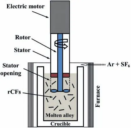
Fig.1.Schematic experimental setup for the high shear dispersion process.
For the extrusion process,all cast samples were machined to produce 150 mm long billets with a diameter of 50 mm.Indirect extrusion was performed on the billets after preheating them to 300 °C for 1 h.This process resulted in round bars with a diameter of 10 mm,corresponding to an extrusion ratio of 1:25.The extrusion was carried out using a 2.5 MN automatic extrusion press (Müller Engineering GmbH &Co.KG).To prevent hot cracking,the ram speed was maintained at a relatively slow rate of 1.4 mm/s.The selection of extrusion parameters was based on previously published reports[26,27].
The microstructural analysis of the extruded samples was conducted using optical microscopy (Leica DMI5000) and scanning electron microscopy (SEM,FEI Quanta FEG 250)equipped with energy dispersive X-ray spectroscopy (EDX).The prepare the samples for analysis,transverse and longitudinal sections were cut from the extruded bars,perpendicular and parallel to the extrusion direction,respectively.The cut samples were then polished with emery papers ranging from 400 to 2500 grit size and 1 μ water-free diamond suspension.For etching,a picric acid-based solution recommended by Kree et al.[28]was employed for a brief period of a few seconds.The average grain sizes of the samples were determined based on linear intercept method.For delicate observation of the reinforcement-matrix interface,the samples to be examined under SEM were not subjected to etching.The textures of the extruded samples were analyzed using an X-ray diffractometer (XRD,PANalytical X’pert PRO MRD)with Cu Kαradiation and a beam size of 2 × 1 mm2.Six pole figures were measured up to a tilt angle of 70° To obtain complete pole figures,normalized and background-corrected pole figures were recalculated from the orientation distribution function using an open-source code called MTEX [29].
Vickers hardness (HV) testing was performed with a load of 2 kgf and a dwell time of 10 s.For both tensile and creep tests,dog-bone-shaped specimens with M10 screw heads were machined from the extruded bars,following the DIN 50125 standard.The specimens had a gage section of Ø6 mm × 30 mm,with their longitudinal axes aligned with the extrusion direction (ED).The RT uniaxial tensile properties of the extruded samples were determined using a universal testing machine (Zwick Z050) with a strain rate of 10-3s-1.Five tensile specimens were tested for each set of samples,and the average results were reported.Tensile creep tests were conducted at a temperature of 150 °C under constant stresses ranging from 40 to 80 MPa.Additionally,tests were carried out under a constant stress of 40 MPa at 125°C and 175°C to determine the activation energies.Lever arm creep machines(ATS)were utilized,wherein creep deformation was measured using two extensometers with a gage length of 30 mm on the specimen.The specimens had a total length of 60 mm,a diameter of 6 mm,and were securely fastened to the clamping with M10 threads.The temperature was directly measured at the clamping point of the specimen and maintained at a constant level with an accuracy of ±1 °C.
3.Results and discussion
3.1.Microstructures
Fig.2 displays the optical micrographs of the reference AZ91 alloy and its CF-reinforced composites taken from the longitudinal sections of the extruded bars.The dark areas in Fig.2b-e indicate the CFs,which were relatively evenly distributed within the matrix.All samples exhibited a typical dynamically recrystallized microstructure characterized by finer and comparatively equiaxedα-Mg grains after hot extrusion.The measured average grain sizes presented in Table 2 demonstrate that the addition of CFs led to a reduction in grain size in the AZ91 alloy.Specifically,with 2.5 wt.% and 5.0 wt.% CF additions,the grain size decreased by approximately 17% and 28%,respectively.This significant grain refinement can be attributed to the enhanced matrix distortion,which subsequently increases the driving force for recrystallization in the presence of CFs [30,31].Furthermore,the CFs acted as pinning sites and likely restricted the grain growth at elevated temperatures [32].On the other hand,the effect of fiber length on the average grain size was found to be insignificant.This observation aligns with the SEM micrographs(Fig.3d,f,h,j),which indicate that the composites contained CFs of similar sizes despite using CFs with different lengths(100 and 500 μm) initially.There could be two potential reasons for the observed reduction in fiber length after extrusion.The first reason is fiber breakage during high shear dispersion in the casting process prior to extrusion.The second reason may be related to fiber fracture resulting from increased asymmetric stresses due to the plastic mismatch between the deformed alloy and the rotating CFs during extrusion [25,33].
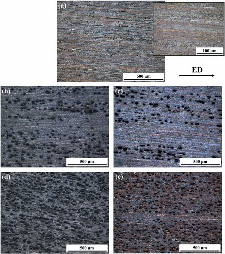
Fig.2.Optical images of extruded (a) reference AZ91 alloy,(b) AZ91/2.5 wt.%CF100,(c) AZ91/2.5 wt.%CF500,(d) AZ91/5.0 wt.%CF100 and (e)AZ91/5.0 wt.%CF500 composites.

Table 2Average grain sizes of extruded samples.
It is evident from Fig.3,which shows the microstructures of both the reference alloy and composites taken perpendicular and parallel to the ED,that the CFs were predominantly aligned in the ED,along with the secondaryβphase composed mainly of Mg17Al12intermetallic.Fig.4a provides a schematic illustration of the formation of stringer intermetallic particles precipitating along the grain boundaries parallel to the ED,as well as the alignment of CFs during hot extrusion.For instance,Fig.4b and c compare the microstructures of the AZ91/2.5 wt.%CF100 composite before and after extrusion,respectively.While the as-cast composite exhibits an average grain size of 65 μm,the extruded composite shows a reduction to approximately 5.9 μm.This suggests that dynamic recrystallization resulted in grain and intermetallic refinement with a more uniform distribution within the alloy.
On one hand,no substantial cavities were detected in the vicinity of CFs embedded into the matrix,except for a few micro-voids,which may indicate improved reinforcementmatrix bonding,as illustrated in Fig.5a showing the microstructure of the AZ91/2.5 wt.%CF100 composite.The EDX analysis in Fig.5b reveals that the CFs were mainly accumulated around the Al-rich intermetallics,consistent with our previous investigation on the as-cast form [20].This segregation of Al,as the major alloying element,on the CF surfaces can be attributed to the fact that the reinforcement was pushed into the secondary phase with a relatively low melting point at the solidification front.On the other hand,it was observed that some CFs tended to interact with the matrix,forming an intermediate layer between them during casting,as shown in Fig.6.As suggested by several published reports,the interfacial products between the carbonaceous reinforcement and liquid Mg-Al alloy are potentially Al4C3and Al2MgC2[35–38].These carbides,which cannot be detected by an XRD device due to their relatively low content as discussed in our earlier study [20],are likely to fracture during extrusion due to their brittle nature.These fractures appear as micro-cracks at the fiber-matrix interface,as indicated in the microstructure of the AZ91/2.5 wt.%CF100 composite in Fig.6.These cracks are considered to be prone to interfacial debonding,leading to a decrease in the mechanical properties.The presence of silicon(Si)and oxygen (O)is also noticeable from the EDX elemental map in Fig.6,suggesting that Si in the alloy composition accumulated around the CF and this reinforcement was oxidized during the composite fabrication.
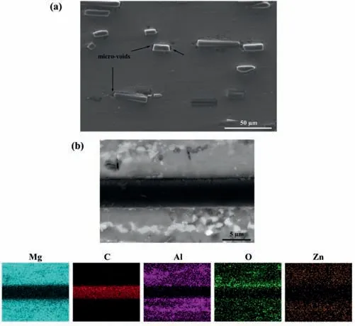
Fig.5.(a) Micro-voids around the CFs and (b) EDX analysis of a single embedded CF in the extruded AZ91/2.5 wt.%CF100 composite parallel to the extrusion direction.
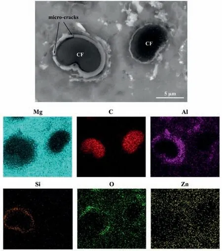
Fig.6.Carbon fiber-matrix interface SEM image and EDX analysis of the extruded AZ91/2.5 wt.%CF100 composite perpendicular to the extrusion direction.
Fig.7 illustrates the crystallographic textures of the extruded round bars in the form of pole figures representing the basal {0001} and prismatic {100} planes of AZ91 alloy and its CF-reinforced composites.The ED is located at the center of the pole figures,and each displacement represents a tilt out of the ED up to 90° around the circle.In all cases,the expected rotational symmetry around the ED is observed.Typically,the basal planes are concentrated at the outer part,indicating a 90° rotation of their normal direction relative to the ED.Additionally,the prismatic planes are somewhat concentrated in the center with deviations,corresponding to the expected 90° tilt due to the lattice structure.This finding is commonly observed in round bar extrusions of Mg alloys,particularly when the microstructure is fully recrystallized.Similarly,the inverse pole figures shown in Fig.8 also indicate distinct texture development during extrusion,but there are no significant changes in the texture with the addition of reinforcement.In other words,the CFs are unlikely to influence the deformation and recrystallization mechanisms that would alter the general substructure of these materials.
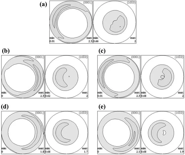
Fig.7.Pole figures {0001},{100} of (a) AZ91 alloy,(b) AZ91/2.5 wt.%CF100,(c) AZ91/2.5 wt.%CF500,(d) AZ91/5.0 wt.%CF100 and (e)AZ91/5.0 wt.%CF500 composites.

Fig.8.Inverse pole figures of (a) AZ91 alloy,(b) AZ91/2.5 wt.%CF100,(c) AZ91/2.5 wt.%CF500,(d) AZ91/5.0 wt.%CF100 and (e) AZ91/5.0 wt.%CF500 composites.
3.2.Hardness and tensile properties
The average values of hardness and tensile test results for hot-extruded AZ91 alloy and AZ91/CF composites are presented in Table 3.Comparing with the extruded alloy,the hardness of composites increased by approximately 16–20%and 23% for 2.5 and 5 wt.% CF contents,respectively.This hardness improvement can be attributed to the grain refinement and the hardening effect of the CFs embedded into the matrix.However,similar to the grain size measurement,no significant difference was observed in the average hardness values of composites with different fiber lengths at the same reinforcement content.The hardness enhancement was also found to be limited in the composites containing 5 wt.% CFs,possibly due to the increased number of micro-voids (Fig.5a)and micro-cracks (Fig.6) surrounding the CFs,resulting from the increased matrix-reinforcement interfacial area.Additionally,other factors such as potential variations across the extruded samples and the varying effectiveness of alignment for broken fibers during extrusion,depending on the initial fiber length and content,may also come into play.

Table 3Hardness and tensile properties of extruded AZ91 alloy and its composites reinforced with CFs.
The representative RT tensile engineering stress versus strain curves of extruded AZ91 alloy and its CF-reinforced composites are presented in Fig.9.With the addition of 2.5 wt.% CF,the average 0.2% proof stress (PS) and ultimate tensile strength (UTS) of AZ91 alloy improved by 5–15%and 2–4%,respectively,depending on the initial fiber length.It is known that the strength improvement in fiber-reinforced composites is generally explained by load transfer from matrix to fibers,enhanced dislocation density resulting from the difference in coefficient of thermal expansion between matrix and reinforcement (upon hot-extrusion),and grain size refinement.The load transfer theory,based on the Shear-Lag model,assumes that the fiber aspect ratio is higher than the critical value ofσf/2τm(whereσfis the fiber tensile strength andτmis the matrix shear strength) for effective load transfer [39–41].The critical value is calculated to be 18.5 based onσf=3500 MPa [20]andτm=94.5 MPa (assumingτm=σm/2,whereσmis the matrix yield strength,which is 189 MPa from Table 3).This suggests that the length of fibers with an average diameter of 6 μm should be greater than 111 μm for effective load transfer.However,the average length of the CFs embedded into the matrix in the longitudinal direction is well below 100 μm,as seen in Fig.3 (b,d,f,h,j),indicating that load transfer is unlikely to play a crucial role in the strengthening.It can be suggested that the relatively poor bonding due to the matrix-reinforcement interaction dramatically impairs the strengthening capacity of enhanced dislocation density as well as that of load transfer.Therefore,the limited strength enhancement in the composites reinforced with 2.5 wt.% CF is considered to be mainly due to the grain size reduction.
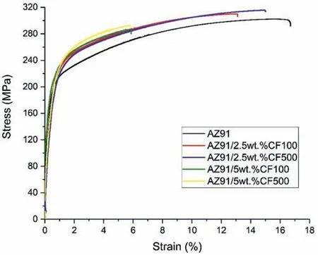
Fig.9.Representative tensile engineering stress versus strain curves of extruded AZ91 alloy and its CF reinforced composites at RT.
When the reinforcement content was increased from 2.5 wt.% to 5 wt.%,0.2% PS and UTS showed fluctuations and a decline,respectively.These divergent PS and reduced UTS values may be ascribed to the fact that the increased addition of CF into the matrix leads to more reinforcement clustering and the formation of interfacial products with microcracks at the CF-matrix interface.It is known that fracture propagation tends to occur through such cracks and micropores within the fiber clusters,resulting in a significant reduction in mechanical properties [42,43].The observed trend,where ductility typically deteriorates with an increasing content of brittle reinforcement,was also observed in this study.The failure strain of AZ91 alloy reduced by 25%and 44–63%with the addition of 2.5 wt.% and 5 wt.% CF,respectively.This reduction in ductility is more likely to be associated with strain concentration and premature failure of the composites as higher reinforcement content causes strain localization,impeding the plastic deformation of the matrix [44].
Although all composite microstructures possess a similar length for the embedded fibers,the AZ91/2.5 wt.%CF500 composite displayed enhanced strength compared to the AZ91/2.5 wt.%CF100 composite,suggesting that the strength increases with the increased length of the as-received CFs at the same content.It is known that distributing reinforcement into the matrix becomes more difficult with decreasing reinforcement size,leading to clustering and agglomeration.It is considered that the as-received CFs with an average length of 100 μm tended to cluster,and these clusters,as indicated in Fig.3c,could not be sufficiently broken during extrusion due to a smaller fiber aspect ratio compared to the as-received CFs with 500 μm average length.Since,fibers or whiskers with a greater aspect ratio are more likely to fracture easily because of their lower fracture strength and the presence of greater flaws [33,45].Shi et al.[33]also stated that the breakage of smaller reinforcement can refine the distance between neighboring reinforcements (λ),and the cracks would easily propagate throughout broken fibers with decreasingλ(due to smaller resistance),leading to lower strength.Therefore,the decline in strength by shorter as-received CFs at 2.5 wt.% content can be attributed to their tendency to cluster into the matrix,hence decreasingλ.However,contrary to what was observed in 2.5 wt.% CF-reinforced composites,shorter as-received CFs (AZ91/5 wt.%CF100) showed improved strength and ductility compared to longer as-received CFs (AZ91/5 wt.%CF500) for 5 wt.% CF-reinforced composites.This variation in mechanical properties is also ascribed to fiber clustering,as the AZ91/5 wt.%CF500 composite has more CF clusters than the AZ91/5 wt.%CF100 composite(Fig.3g and i).It can be suggested that a single-pass extrusion may not be sufficient to effectively break and homogenously distribute the longer CFs that become entangled with each other at higher contents.
Fig.10 reveals the representative SEM fracture surface images of extruded AZ91 alloy and its CF-reinforced composites for investigating the fracture mechanisms.Almost all fracture surfaces exhibit dimples and tear ridges,indicating a relatively ductile fracture.Unlike the fracture surface of the cast composites [20],fiber debonding was not observed on these fracture surfaces of extruded composites.It is evident that the CFs aligned in the extrusion (tensile) direction were broken,and the dimples formed in the vicinity of fractured fiber by fragmenting the intermediate layer,i.e.weak physical bonding,into many pieces (Fig.10b).This may suggest that the stress is concentrated around the CFs,and some of the load is borne by these fibers during tensile deformation,demonstrating their strengthening effect.However,the limited strengthening is likely due to inefficient stress transfer between the matrix and CFs caused by the fragmentation of the intermediate layer.Fiber breakage is considered to be the main fracture mechanism in these extruded CF-reinforced Mg matrix composites.The alloy and AZ91/2.5 wt.%CF100 composite exhibit larger voids compared to the other composites.Additionally,the composites with 2.5 wt.% CFs (Fig.10b and c)show relatively smaller dimples compared to those containing 5 wt.% CFs (Fig.10d and e),which is consistent with the observed trend of reduced ductility with increasing fiber content in Table 3.
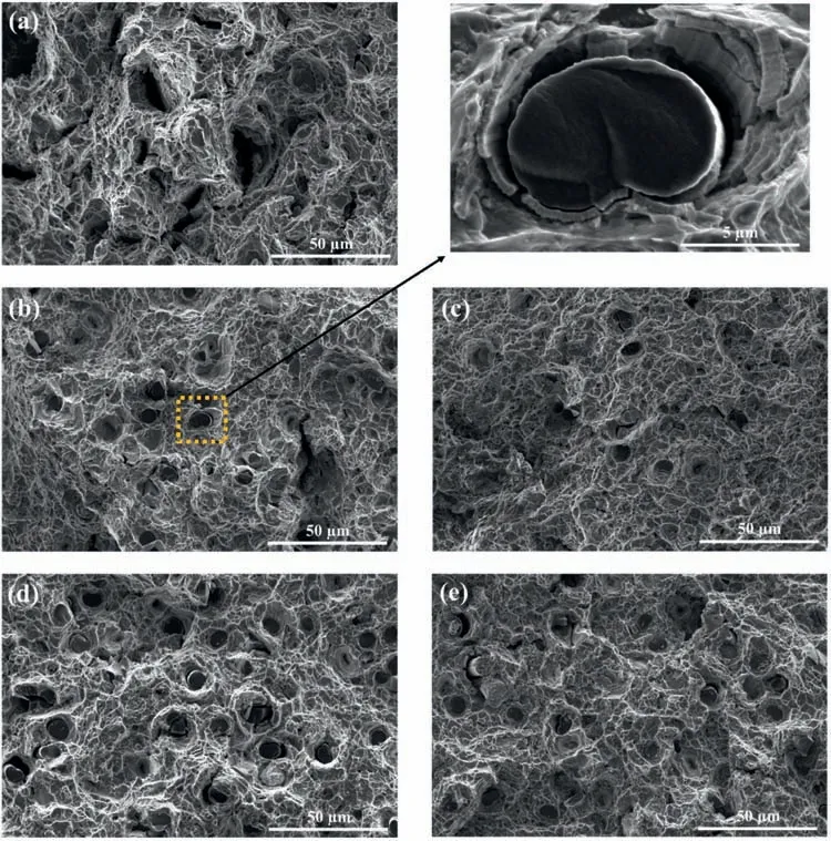
Fig.10.SEM tensile fracture surface images of extruded (a) AZ91 alloy,(b) AZ91/2.5 wt.%CF100,(c) AZ91/2.5 wt.%CF500,(d) AZ91/5.0 wt.%CF100 and(e) AZ91/5.0 wt.%CF500 composites.
3.3.Creep properties
The dependence of the minimum creep rateεsin a creep test on the applied constant stressσand temperatureTis described in Eq.(1).
whereAis a material dependent constant,Gthe shear modulus,bthe Burgers vector,kthe Boltzmann constant andnthe stress exponent,which gives information about the rate-controlling deformation mechanisms during creep.Tensile creep tests at 150 °C were carried out at constant stresses between 40 and 80 MPa in order to determine stress exponents using the minimum creep rates obtained from the creep curves.As an example,the tensile creep curves from tests at constant temperature of 150 °C and 40 MPa are shown in Fig.11a.The curves in Fig.11a show a very short,primary creep stage during which work hardening takes place.This is followed by the secondary,stationary creep phase,during which softening and hardening take place simultaneously and balance each other in amount.This second phase is followed by the tertiary creep stage,during which the materials only soften and the creep rate increases.The third stage ends with the failure of the specimens.The stress exponent n can be determined by plotting the minimum creep rates versus the applied constant stresses in a double logarithmic plot.
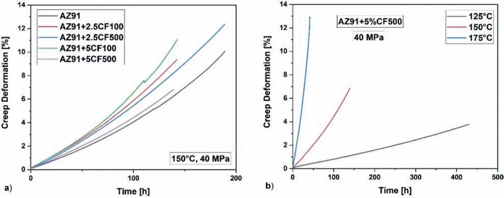
Fig.11.(a) Creep curves of all materials tested at 150 °C and 40 MPa and of (b) AZ91/5wt% CF500 tested at constant stress of 40 MPa at different temperatures of 125 °C,150 °C and 175 °C.
To determine the activation energy during creep in tests at constant stress and different temperatures,creep tests were carried out at 40 MPa and temperatures of 125 °C,150 °C and 175°C,represented as examples of AZ91/5wt%CF500 in Fig.11b.D is the diffusion coefficient,and it can be expressed as:
whereD0is the frequency factor andQCthe apparent activation energy for creep.
Fig.12 shows the double logarithmic plot of minimum creep rate versus applied stress for creep tests at 150 °C.The slopes of the lines correspond to the respective stress exponent n.The line of AZ91 lies furthest down,i.e.it has the lowest minimum creep rates.Thus,no strengthening effect has occurred due to the recycled CF.
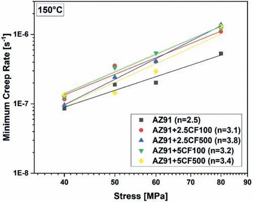
Fig.12.Double logarithmic plot of minimum creep rate versus applied stress from creep tests at 150 °C and stresses of 40,50,60,and 80 MPa.
In the literature,stress exponents ofn=1 are attributed to creep deformation where diffusion processes are the ratedetermining deformation mechanisms [46,47],n=2 corresponds to creep deformation dominated by grain boundary sliding (GBS) [48],andn=3 to creep deformation where viscous glide of dislocations is dominant [49–51].Dislocation climb as the rate-determining deformation mechanism corresponds to a stress exponent ofn=5[50–52].The stress exponent of the AZ91 is 2.5 and that of the CF-reinforced AZ91 ranges between 3.1 and 3.8.Therefore,it seems that grain boundary sliding can be considered as a rate-determining deformation mechanism in the unreinforced AZ91 and that the dominance of grain boundary sliding is weakened by the recycled CFs in the composites,as the stress exponents become larger than 3 and thus reach the range of dislocationdominated deformation mechanisms.
In order to determine the activation energy of creep (Qc),plots were drawn of the minimum creep rate versus the inverse temperature of creep tests at 40 MPa constant stress(Fig.13).According to Eq.(2),Qccan be calculated from the slope.All determined activation energies range between 36 and 48 kJ/mol and therefore are significantly smaller than the activation energy for self-diffusion in magnesium QSD=135 kJ/mol [53,54]and for grain boundary diffusion in magnesium QGB=92 kJ/mol [55].A similarly low value of the activation energy at low creep stresses was found for dispersion-strengthened magnesium,here the values were around 48 kJ/mol[56].The dominant deformation mechanism identified was grain boundary sliding,which is inhibited by dispersoids at the grain boundaries.
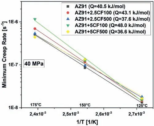
Fig.13.Plot of the logarithm of minimum creep rate versus 1/T of creep tests 40 MPa and temperatures of 125 °C,150 °C,and 175 °C.
Stress exponents ofn=2 and activation energy for creep of 30–45 kJ/mol have been determined in creep studies,also carried out on AZ91.Grain boundary sliding identified by marker line offsets has been identified as the dominant deformation mechanism as well [57].It is said in [57]that GBS is likely to happen in materials with grain sizes smaller than 10 μm,which is the case here.
4.Conclusions
In the present study,the following conclusion can be drawn from the investigations.
1.The CF-reinforced magnesium matrix composites were successfully produced through stir casting followed by onepass hot extrusion.It was observed that the majority of the CFs with initial average fiber lengths of 100 and 500 μm were broken during extrusion and uniformly aligned in the ED,resulting in grain and intermetallic refinement compared to the matrix alloy.The grain size of the matrix decreased by approximately 17% and 28% with increasing reinforcement content of 2.5 and 5.0 wt.% CF,respectively.The pole figures indicated no significant difference in the crystallographic textures of the extruded round bars with the addition of CFs.
2.In comparison to the unreinforced AZ91 alloy,the composites with 2.5 wt.% CF exhibited improved hardness by 16–20% and yield strength by 5–15%,primarily due to grain refinement,while ductility was reduced.At a higher CF content of 5.0 wt.%,the 0.2% PS and UTS fluctuated and declined,respectively,which is ascribed to an increased clustering tendency of the reinforcement and weak physical bonding observed between the matrix and CFs.At a 2.5 wt.% CF content,the composite with an initial average fiber length of 100 μm showed improved strength compared to the composite with a fiber length of 500 μm,suggesting that strength increases with longer as-received CFs at the same content.However,shorter CFs exhibited better strength performance than longer fibers at a 5 wt.% CF content due to increased fiber clustering in the AZ91/5 wt.%CF500 composite.Fiber clustering resulted in a shorter distance between neighboring CFs,diminishing resistance to crack propagation and thus reducing strength.
3.Tensile creep tests demonstrated that the CFs did not enhance the creep resistance of extruded AZ91 at 150 °C.The stress exponent (n=2) and activation energy for creep(Qc=36 -48 kJ/mol) indicated that grain boundary sliding is the dominant deformation mechanism during creep.
Declaration of competing interest
The authors declare that they have no known competing financial interests or personal relationships that could have appeared to influence the work reported in this paper.
Acknowledgments
The authors express their gratitude to the German Academic Exchange Service (DAAD) for providing a scholarship to Dr.Sinan Kandemir during his tenure at Helmholtz-Zentrum Hereon (HZH),formerly known as Helmholtz-Zentrum Geesthacht,to conduct this research.The authors also acknowledge HZH and the Materials Research Center at Izmir Institute of Technology for granting access to their laboratory and SEM facilities,respectively.Furthermore,the authors extend their appreciation to CarboNXT GmbH(www.carbonxt.de) for supplying the carbon fibers utilized in this study.
 Journal of Magnesium and Alloys2023年7期
- Journal of Magnesium and Alloys的其它文章
- Recent progress in MgB2 superconducting joint technology
- “Smart” micro/nano container-based self-healing coatings on magnesium alloys: A review
- Recent advances using equal-channel angular pressing to improve the properties of biodegradable Mg–Zn alloys
- Twin evolution in cast Mg-Gd-Y alloys and its dependence on aging heat treatment
- Effects of Ce content on the modification of Mg2Si phase in Mg-5Al-2Si alloy
- Solute drag-controlled grain growth in magnesium investigated by quasi in-situ orientation mapping and level-set simulations
