Recent progress in MgB2 superconducting joint technology
Ho Ling ,Dipk Ptl,1 ,Mhooh Shhzi ,Anrzj Morwski ,Dnil Gj ,Mtt Rinlish ,Rihr Tylor,Yusuk Ymuhi,M Shhrir A.Hossin,g,*
aSchool of Mechanical and Mining Engineering,The University of Queensland,St Lucia,Queensland 4072,Australia
b QUT Centre for Materials Science and School of Chemistry and Physics,Queensland University of Technology,Brisbane,Queensland 4001,Australia
cInstitute of High Pressure Physics,Polish Academy of Sciences (PAS),Sokolowska 29/37,Warsaw 01-142,Poland
d Institute of Low Temperature and Structure Research,Polish Academy of Sciences (PAS),Okólna 2,Wrocław 50-422,Poland
e Hyper Tech Research,Inc.,539 Industrial Mile Rd,Columbus,Ohio 43228,USA
fApplied Superconductivity Laboratory,Queensland University of Technology,Brisbane,Queensland 4001,Australia
g Australian Institute for Bioengineering and Nanotechnology (AIBN),The University of Queensland,St Lucia,Queensland 4072,Australia
h Department of Materials Process Engineering,Graduate School of Engineering,Nagoya University,Furo-cho,Chikusa-ku,Nagoya 464-8603,Japan
Abstract Magnesium diboride (MgB2) magnets have the potential to be the next-generation liquid-helium-free magnet for magnetic resonance imaging (MRI) application due to their relatively high superconducting transition temperature,high current density and low raw material cost compared with current commercial niobium-titanium (Nb-Ti) magnets.A typical superconducting magnet includes several coils.To produce an ultra-stable magnetic field for imaging in MRI,a superconducting electromagnet operating in a persistent mode is crucial.Superconducting coils of the electromagnet in MRI are short-circuited to operate in the persistent mode by connecting coils with superconducting joints.Persistent joints have been demonstrated for in-situ and ex-situ wires of both mono-and multi-filamentary structures,made predominantly by PIT techniques similar to those used in wire production.To realise further engagement of MgB2 in MRI applications,enhancing the performance of MgB2 superconducting joints is essential.This literature review summarises research and development on MgB2 superconducting joining technology.
Keywords: MgB2;Superconducting joints;Persistent-mode magnets;MRI application;Field-decay measurement.
1.Introduction
Superconducting materials lose their resistance when they are cooled below a certain temperature known as a critical temperature (Tc).BelowTc,superconducting materials have the unique ability to transport large direct current (DC) without any electrical dissipation.Therefore,superconducting materials are widely used for winding electromagnets to produce strong magnetic fields with low power consumption.Another distinct feature of an electromagnet wound using a superconducting conductor is its ability to retain current in it when two ends of the magnet are short-circuited using a‘superconducting joint’.This feature is commonly used in magnetic resonance imaging(MRI)and nuclear magnetic resonance(NMR)applications to produce an ultra-stable magnetic field with a decay rate of less than 0.1 ppm h-1.A persistent-mode operation is the operation mode to run a superconducting magnet in a closed circuit.
Currently,ASG Superconductors has developed a driven mode MRI system and Hitachi has developed an MgB2magnet for MRI system [1,2].A superconducting magnet used in MRI is usually assembled using more than one coil because of the limited length of a single wire,to meet field shape requirements,to keep the individual coil size in accordance with manufacturability and to have the ability to maximise central field strength by surrounding higher-and lower-field coils [3].These coils are connected using superconducting joints and the ends of the first and the last coil are connected using a persistent current switch (PCS,a small non-inductively wound superconducting coil) and superconducting joints [4].Thus,technology for producing superconducting joints becomes crucial to realise the persistent-mode operation.
Technology for producing superconducting joints using superconducting lead-bismuth (Pb-Bi) solder is matured and routinely used in industry for low-temperature superconductors (LTS) such as niobium-titanium (Nb-Ti) and niobium-tin(Nb3Sn) [5,6].Due to the toxic nature of Pb,research is underway to utilise Pb-free superconducting solder for joining LTSs [7].Since the commercialisation of high-temperature superconductors (HTS),it was believed that sooner or later an HTS magnet would replace the Nb-Ti magnet in MRI as a liquid-helium-free magnet option to reduce operating costs.However,the costs of the HTS conductors,the inability to produce sufficiently long-length single-piece HTS conductors and the inability to produce good quality superconducting joints for persistent-mode operation have not made it possible to introduce HTS in commercial MRI systems [8].In fact,until now,the superconducting joining process to connect HTS was not available.Recently,several superconducting joining methods for rare-earth barium copper oxide (ReBCO)superconductors have been reported [6,9-12].Further research is underway to perfect the joining process to produce highperforming superconducting joints [13].
Apart from LTS and HTS conductors,another superconductor,magnesium diboride (MgB2),which is often regarded as a medium temperature superconductor (MTS) due to itsTcof about 39 K is considered a potential candidate to replace Nb-Ti in MRI magnet [14].MgB2was first found to be superconducting in 2001 by Akimitsu et al.[15].Similar to LTS and HTS,to utilise MgB2in MRI applications driven by persistent mode,superconducting joining technology will be necessary.A significant amount of work has been done to join unreacted mono-and multifilament MgB2conductors but successful joining results using reacted MgB2conductors have been limited.There are three types of MgB2conductors which arein-situ,ex-situand internal magnesium diffusion(IMD) processed MgB2.In-situconductors are fabricated by sintering unreacted Mg and B powders to facilitate the solidstate reaction.Meanwhile,ex-situconductors are fabricated by sintering reacted MgB2powder to recrystallise MgB2superconducting phase.Moreover,IMD-processed conductors use an Mg rod surrounded by B powder and the MgB2phase is formed by Mg diffuses into the B site [16].
This review summarises the research and development made to date on MgB2superconducting joining technology.First,the superconducting joining methods of various types of MgB2conductors are summarised.Subsequently,the performance of reported joints is collected and compared.The next section discusses microstructural features and their potential impact on performance.Finally,persistent-mode MgB2magnets or coils developed to date are demonstrated.By reviewing the history of joints of MgB2conductors,the development towards the future of persistent-mode MgB2magnets or coils can be determined.
2.Structure of superconducting MgB2 joints
The general fabrication processes are similar.The first step of fabrication is the etching of the surrounding matrix material of the conductors with nitric acid or mechanical polishing.The next step is forming a superconducting interface between MgB2conductors by heat treatment.This section provides descriptions of different joint designs and structures.The MgB2joints are categorised based on the type (in-situ,ex-situor IMD) and the state (reacted or unreacted before joining) of the conductors used for joining.
2.1.Superconducting joints of in-situ or ex-situ unreacted MgB2 conductors
Most researchers usedin-situprocessed MgB2monofilament or multifilament wires to fabricate superconducting joints.In this section,fabricating methods usingin-situMgB2conductors are summarized.
The first joint ofin-situMgB2conductors was fabricated by Li et al.[17].The joint structure and process are shown in Fig.1(a).Firstly,one side of the metal sheaths of each conductor was mechanically peeled off by polishing.The peeled sheath length was around 5–10 mm.After peeling,the filaments were exposed for further joining.In the next step,two tapes were aligned facing the exposed surface and joined after filling the Mg+2B pre-mixed precursor between the exposed surfaces.After filling and joining,the contacting area was wrapped with Cu foil to protect the contact surface and increase the strength of the joining.A pressure of around 0.6 GPa was applied to the contacting area to increase its density and strength further.The last step was a heat treatment that lasted for 1 h at a temperature of 973 K in an argon gas environment.
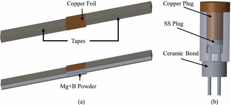
Fig.1.A schematic drawing of the joining process reported by (a) Li et al.and (b) Park et al.[17,18].
Yao et al.and Park et al.proposed similar methods of joining monofilament and multifilament MgB2conductors [18,19].Fig.1(b) demonstrates their process of joining.Firstly,the wires were etched with nitric acid for 1–2 h to remove the Cu and Monel matrix surrounding the MgB2cores.The exposed part of MgB2cores after etching was about 15–20 mm long.Since the end of exposed cores had been contacting air for a long time (oxygen was trapped and negatively impacted superconducting performance),the exposed cores were trimmed around 3–5 mm.A stainless steel (SS) billet was made in the next step to allow further joining process.The two wires were inserted into the billet with exposed cores inside the billet.The ceramic bond was applied to achieve sealing to prevent Mg from evaporating and escaping the billet during heat treatment.After this,premixed Mg+2B powder was filled in the billet as shown in Fig.1.Then,a copper plug was inserted into the mould and pressurised to make the powder compact.Finally,heat treatment was applied to the joint.
In 2013,Ling et al.also proposed a joining method usingin-situmonofilament wires [20].An image of the apparatus used for the joining process is shown in Fig.2(a).The first step of joint fabrication was etching the Cu and Monel with nitric acid.Secondly,the filament was sheared at an acute to expose more MgB2filament cross-section.Thirdly,similar to the previous method,a Cu plug was inserted into the billet without pressure following filling it with Mg+2B precursor.Fourthly,wires were inserted into the billet from the opening between the Cu plug and the billet.In the next step,the gaps in the top surface of the billet were all sealed with a ceramic paste.Finally,heat treatment was applied to the joint at 700°C for 90 min.Compared to previous methods,there were three advantages in this method,which are: (i) the possibility of breaking brittle exposed filaments is lowered by aligning with the direction of pressing;(ii) the exposed filament was sheared to an acute angle to increase the contacting area of the wires;(iii) the use and assembly of equipment used in this method were more convenient [20].After 2 years,this fabrication method was filed as a patent by Hahn et al.[21].Kim et al.used a similar method in 2017,the only difference was the heat treatment adopted by Kim et al.,675 °C for 1 hour in an argon gas environment [22].In 2021 Tanaka et al.reported a special heat-treatment method that allowed the scheduling of MgB2joints by itself was designed [23].The joint fabrication method was the same as the structure of the heating instrument as shown in Fig.3(a).At the start of heat treatment,the temperature was increased at a rate of 3°C per minute to 700 °C with a contribution from Ling et al.proposed in 2013 which has been already discussed [20].An additional heating system (cartridge heater) was designed for joint heat treatment.The temperature of the furnace was set to 600 °C,and the cartridge heater increased the temperature to a further 100 °C.After hitting 700 °C and holding for 1 hour,the temperature inside the furnace was decreased back to 600oC and dwelled for 11 h.
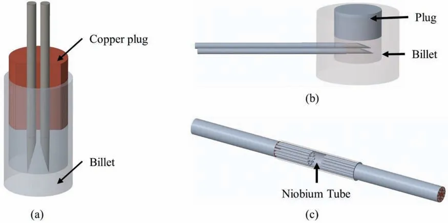
Fig.2.Schematic drawings of joining structures reported.(a) Ling et al.[20].(b) Patel et al.[24].(c) Pradhan et al.[30].
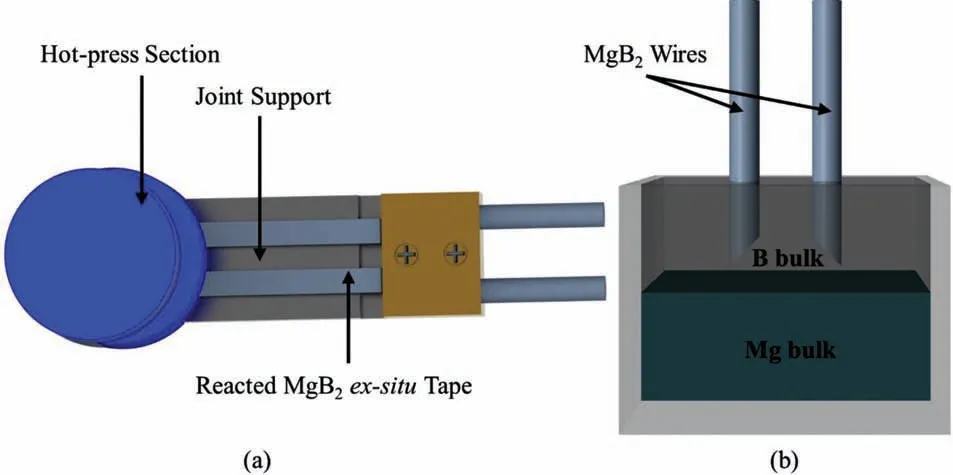
Fig.3.Joining methods of reacted ex-situ and reacted in-situ MgB2 conductors.(a) A schematic drawing of the joint of reacted ex-situ conductors fabricated by Oomen et al.[35].(b) A schematic drawing of the joint of reacted in-situ conductors by Luo et al.[36].
In 2015,Patel et al.reported a new approach to fabricating superconducting joints usingin-situmonofilament MgB2wires (Fig.2(b)) [24,25].The first step was also the removal of the Cu and Monel array surrounding the filament.In this method,the Cu/Monel sheath was removed using nitric acid and the Nb layer was mechanically peeled off.In the second step,the exposed filaments of each wire were arranged in a transverse position with super glue.Thirdly,the wires were inserted into a SS billet and the connecting section between the wires and the SS billet was covered by the hightemperature sealing material.The sealing material was then cured at room temperature for 24 h to improve its flexibility.Fourthly,unreacted pre-mixed Mg+2B powder was filled in the billet,covering the exposed filaments inside the billet in an argon gas environment.The Argon gas environment helped to reduce the trapping of oxygen in the unreacted Mg+2B powder and as a result,the performance of the joint was improved.After this,an SS plug was used to press the powder and the gaps on the top surface were filled with a sealing material.Finally,heat treatment was applied at 690 °C for 30 min in an argon gas environment after room temperature curing of sealing material.
The method of Patel et al.was later modified by Yoo et al.to fabricate superconducting joints usingin-situmultifilament MgB2wires.Compared to the pre-modified method,exposed filaments were cut to different angles after etching and peeling to optimise performance.Exposed wires were separately inserted in two holes and the requirement of super glue was eliminated.The heat treatment was applied at 675 °C for 60 min in an argon gas environment [26].Patel et al.improved this method again and an ultra-low resistance MgB2joint was obtained.They optimised the pressure applied when compacting unreacted powder and heat treatment conditions[27].Patel et al.published articles on joints ofin-situmultifilament wires [28,29].The joint structure was similar to Fig.2(b) but the orientation of the wires was different.
In 2016,Pradhan et al.proposed another method of joiningin-situmonofilament MgB2wires as shown in Fig.2(c) [30].Other than using SS billet like previous methods,a niobium tube was used to join wires.Firstly,after etching and peeling wires,the Nb tube was filled with unreacted Mg+2B powder.Then,wires were properly inserted in the tube from both ends for further rolling in a grooved roller.The diameter of the Nb tube was reduced and the powder inside it was compacted with wires buried within the compacted powder.Finally,heat treatment was applied at 675 °C for 1 h in an argon gas environment.Recently,Hušek et al.and Xi et al.both reported joints of multifilament MgB2wires with similar structures [31,32].In the work of Hušek et al.,the wires were cut and polished at an angle of 15°.The intermediate connection part of Xi et al.was fabricated by drilling a hole in a monofilament wire with an Nb barrier.In 2021,Kim et al.publishedin-situmultifilament MgB2joints with a similar joint structure to Fig.3(b).The intermediate bulk was a combination of Mg+2B and wt.10%ex-situMgB2powder[33].The joint structure shown in Fig.3(b) was used with a pressure of 350 MPa applied on the top plug.The joint was sintered at 600 °C for 4 h.
2.2.Superconducting joints of reacted in-situ or ex-situ MgB2 conductors
The first joint fabricated betweenex-situMgB2materials was reported by Branccini et al.in 2007 [34].However,they did not explain their method of joining in their article.Later in 2008,Li et al.reported a joining method[17],but this method was not effective for joining multifilamentex-situMgB2tapes.The joint structure and process were shown in Fig.1.
In 2014,Oomen et al.from siemens corporate technology proposed a method of joining reactedex-situMgB2tapes as shown in Fig.3(a) [35].Firstly,the tapes were cut at an angle of 10° and positioned transversely on joint support.The cut surfaces were facing up.Moreover,unreacted Mg+2B mixed powder was poured on the top of cutting surfaces for joining purposes.After the surfaces were covered with powder,it was hot-pressed to fabricate an MgB2joint.
In 2019,Luo et al.reported a new joining method for joining reacted conductors with an IMD-processed intermediate bulk [36].The general structure of joining is shown in Fig.3(b).Firstly,two reacted wires were cut at an angle of 45°.In the next step,the cut wires were positioned in a mould,by keeping 5 mm between them and filled with B powder.Then,pressure is applied to the B powder to obtain a B bulk with wires inserted,and a magnesium bulk is also prepared in the same method.Furthermore,the B bulk with wires inserted is positioned on top of the Mg bulk in a SS container.Finally,heat treatment is applied in a hydrogen gas atmosphere.The temperature inside the furnace is increased to 700 °C at a rate of 10 °C per minute and kept for 2 h.
2.3.Superconducting joints of IMD-processed MgB2 conductors
In recent years,MgB2joints for internal magnesium diffusion (IMD) processed MgB2wires are being developed as IMD-processed MgB2wires have certain advantages in superconducting performance compared to traditional powderin-tube (PIT) processed MgB2wires.
In 2018,Matsumoto et al.reported superconducting joints using IMD wires [37].The method of joining is shown in Fig.4.Firstly,two unreacted IMD-processed wires were pressed to form tapes by using a pressing machine.Secondly,one side of the metal sheaths of both the tape-shaped wires(surrounding the inner boron powder layer) was pilled off to expose the B layers.Further,two exposed B-layer surfaces were aligned to face each other and covered with a metal tube.The metal tube was pressurised to combine both wires.Finally,heat treatment was applied at 670 °C for 6 h in an Ar gas environment.During the heat treatment,the magnesium was diffused into B layers to form an MgB2interface in the joint.
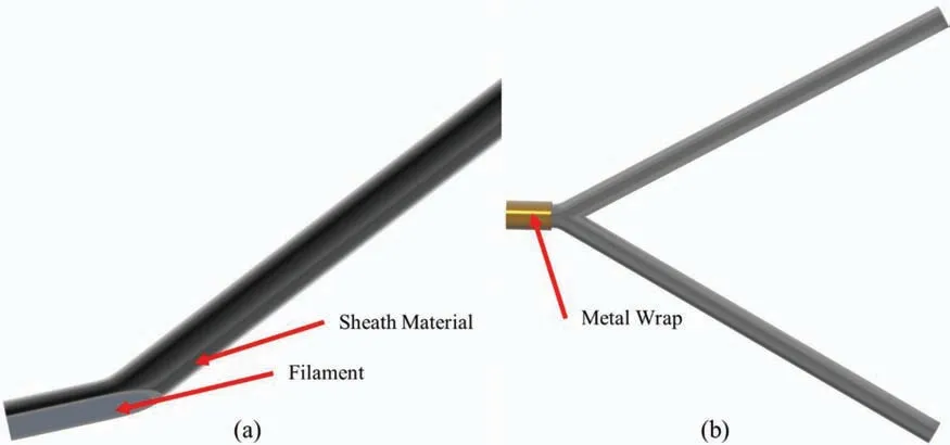
Fig.4.Schematic drawings of joints of IMD processed joints reported by Matsumoto et al.[37].(a) The joined wires which were pressurised and peeled.(b)Joint fabricated by surrounding the joined section with metal tube and pressurised to bond the wires.
In 2021,Patel et al.reported a joining method of IMDprocessed MgB2conductors [38].A similar joint structure shown in Fig.2(b) was used.Firstly,the B powder was filled in the mould and a pressure of around 15 kN was applied by a hydraulic press.Secondly,Mg powder was filled on the top of the pressed B layer and further compressed with 15 kN pressure.Lastly,heat treatment was applied at 670 °C for 12 h in an inert environment.After the heat treatment,a void(shown in Fig.9(b)) could be detected between the SS plug and the joint intermediate,since the Mg on the top diffused into the bottom B layer.
3.Performance of superconducting joints
The performance of the MgB2superconducting joints is influenced by the type of MgB2conductors used for fabricating the joints.In 2007,the first attempt was made to join two monofilament MgB2wires.The surrounding matrix of the wires was pure nickel.Later,both monofilament and multifilament MgB2wires were attempted to be joined.Various combinations of materials were used for fabricating different types of conductors,and the major matrix materials were Fe,Cu,Mo and Nb.The detail of the matrix material used in different MgB2conductors is shown in Table 1.
Joints of NbTi multifilament wires can be made by soldering,but using a superconducting soler (lead-tin,or low lead content tin-indium with 5 wt% lead) will decrease theTcof the joint[43].To avoid this,heat treatment is critical for joints of MgB2superconductors fabrication,since the MgB2intermediate will maintain theTc.Heat treatment condition is another parameter that affects the performance of MgB2superconducting joints.As a result,the temperature during heat treatment should be controlled at a proper level.Although the melting point of MgB2is high,MgB2tends to decompose to the non-superconducting phase at high temperatures.Thus,reheating already reacted precursor to recrystallise the superconducting phase can cause poor connectivity [17].To improve the connectivity,unreacted Mg+2B is often used as an intermediate between conductors and heat treatment in the range ≥600 °C is used for the reaction [6].
In this section,the performance of MgB2joints is analysed.The performance is analysed based on theirIcvalue,Icretention ratio (CRR,which is determined by theIcvalue of the joint as a percentage of theIcvalue of the unjoined wires)[6],and resistance.All MgB2joints reported to date are separated into three groups according to the type of conductors joined,i) Joints ofin-situMgB2conductors,ii)ex-situMgB2conductors and iii) unreacted IMD processed MgB2conductors.To analyse joint performance based on real MgB2MRI operating temperature and field range,the superconducting performance is analysed at around 15 K and 0.5 T.
3.1.Superconducting joints performance of in-situ conductors
Fig.5(a) to (d) demonstrates theIcvalue of joints fabricated within-situMgB2superconductors in a temperature range of 10 K to 21 K.In Fig.5(a),Ling et al.reported a joint ofin-situmonofilament MgB2conductors which demonstrated anIcvalue of approximately 270 A.Moreover,the highestIcvalue (262 A at 20 K in self-field) of the joint of multifilamentin-situconductors were obtained by B.Yoo et al.[26],as shown in Fig.5(b).The method of their joint fabrication is mentioned in section 6.1.One of the major causes of this highIcvalue was the shearing angle of 13°.By cutting conductors at an angle of 13°,the contact area between conductors and intermediate bulk material was increased,which enhanced the connectivity and thereby enhance theIcvalue.Besides,a pressure of 300 MPa was used to compact the intermediate bulk powers[26].In addition to the highIcvalue,a high CRR value of 83% was obtained.

Fig.5. Ic of joints of in-situ.Produced with data from [18,20,22-30,32,33,38,44](a) Ic of joints of in-situ monofilament superconductors at 20 K and 21 K.(b) Ic of joints of in-situ multifilament superconductors at 4.2 K and 20 K.(c) Ic of joints of in-situ superconductors 15 Kand 16 K.(d) Ic of joints of in-situ superconductors at 10 K.
Amongst all the data,Tanaka et al.obtained the highestIcvalue which is about 450 A in self-field (0 T) (measured by the four-probe method) at 15 K [23](shown in Fig.5(c)).They used unreacted monofilament MgB2wires with a special heat-treatment method to improve their current carrying capacity.The heat-treatment schedule was 700 °C for 1 h and 600 °C for 11 h [23].The initial heat treatment at 700 °C for 1 h promoted the reaction between Mg and B because the heating temperature was more than the melting temperature of Mg(650°C).When the heat-treatment condition was changed to 600 °C for 11 h,a uniform reaction between Mg and B happened and formed MgB2with a small amount of impurity.As a result,a highIcvalue could be obtained.Furthermore,some joints with relatively lowIcvalues at around 20 K in self-field are also shown in Fig.5(a).In 2017,Kim et al.reported anIcvalue of 22 A at 20 K using monofilament MgB2conductors,which is a relatively low value compared to other values [22].Besides,a CRR value of 35% was reported.The heat-treatment condition applied by Y.G.Kim was 675 °C for 1 h which was the same heat-treatment condition applied by Yoo et al.[26].The major difference was the number of filaments in the conductors.Multiple lowIcvalues were also reported by Park et al.[18].The cause of lowIccould be the addition of C.C-doping is capable of improvingIcperformance in high-field,but low-field performance is depressed simultaneously [18].
Researchers focused on joints of multifilament wires recently since they are more feasible for MRI application compared to monofilament wires.As shown in Fig.5(b),Yoo et al.reported a joint of multifilament wires with a CRR value of 87%.In 2021,Xi et al.reported a joint of C-doped MgB2multifilament wires with higher performance than the joint of monofilament C-doped reported by Yoo et al.[26,32].However,the CRR was approximately 40%.Further,in 2021,Kim et al.reported a CRR value over 100% of a joint of unreacted multifilament wires [33].The performance of the joint in the high field was better than the unjoined wires.The intermediate bulk fabricated by Mg+2B powder mixed withex-situMgB2powder successfully joined the multifilament wires.Both of these two joints tended to use a low sintering temperature of about 600 °C.The sintering dwelling time applied by Xi et al.was 2 h,and Kim et al.applied 4 h.
3.2.Performance of superconducting joints of ex-situ MgB2 conductors
Fig.6 displays theIcvalues of the joints fabricated usingex-situMgB2conductors.Braccini et al.reported anIcvalue of 70 A at 20 K in self-field for the superconducting joints fabricated using fully-reactedex-situmultifilament tapes [34].The firstIcresult was reported by Penco et al.from the ASG group in 2007 which was about 40 A at 20 K in self-field[46].Later in 2010,the same group reported a high transport current in a closed-loop ofex-situmultifilament tapes [47].They managed to put a transport current of 300 A in a closedloop superconducting joint [47].Later in 2014,Oomen et al.reported anIcof a joint of reactedex-situconductors which shows 50 A at 15 K in self-field [35].
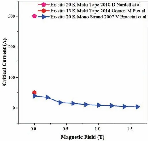
Fig.6. Ic of joints of ex-situ MgB2 conductors.Produced with data from[34,35,47].
3.3.Performance of superconducting joints of IMD-processed MgB2 conductors
Fig.7 shows theIcvalues of the joints of IMD conductors at 20 K in various fields.The joint with a higherIcvalue was reported by Patel et al.in 2021 [38].A highIcvalue of 160 A in self-field at 20 K was reported.The joint of IMD conductors was capable of carrying almost identical current compared to virgin IMD conductors in various fields.This was the first work that realised a CRR of approximately 100% with negligible degradation after joining [38].Icvalues in various fields were reported by Matsumoto et al.in 2018,which was much lower than the work of Patel et al.[37].Although joints were both fabricated under the concept of IMD,their fabrication methods were different (the fabrication method is discussed in Section 2.3).The joint of reacted MgB2wires fabricated by Luo et al.was showing a lowerIcvalue compared to the work of Patel et al.,due to the reacted wires.However,this joining method is more desired in the industry.Besides,Hušek et al.achieved a high-performance joint at 4.2 K in a range of fields from 5 T to 8 T.Different joining methods lead to different performances since the resultant microstructures tend to differ.The impact of microstructure is discussed in Section 4.
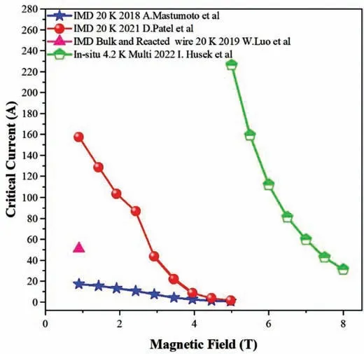
Fig.7. Ic of joints of IMD processed and reacted MgB2 conductors [31,36-38].
3.4.Resistance of MgB2 superconducting joints
The resistance of MgB2superconducting joints fabricated using different conductors at around 20 K is summarised in Table 2.Amongst all the resistance values,the lowest resistance of 5.48×10⁻¹⁵Ωwas achieved by Patel et al.for the joint fabricated usingin-situmultifilament MgB2wires [27].The joints fabricated usingin-situmultifilament conductors tend to possess low resistance at 20 K compared with the joints fabricated usingin-situmonofilament conductors.Forex-situtapes,Nardell et al.reported a relatively lower resistance of 1.00×10⁻¹⁴Ωat 20 K in self-field [47].
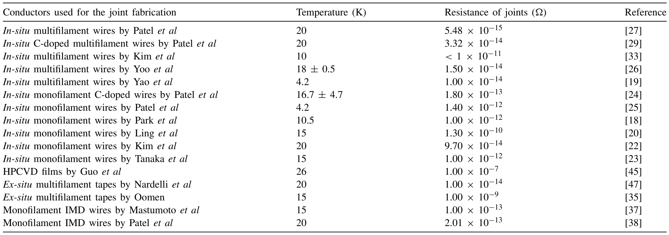
Table 2Resistance of MgB2 superconducting joints.
3.5.Summary
TheIcdata of various joints is significantly related to the wires used for fabrication,so the CRR can be considered a critical factor for justifying the performance of each joint.Amongst articles published so far,Patel et al.achieved 100%CRR and Kim et al.achieved over 100% CRR [33,38].Both methods can be further investigated in the future.IMD bulk will be more condensed which can provide better connectivity to improve the joining interface between wires and the bulk.There is only one article that reported joints of reacted wires with IMD bulk by Luo et al.with relatively low performance in 2019[36].Combined with the work from Patel et al.,joints of reacted wires with IMD bulk can be expected to show improved superconducting performance.The joints of unreacted multifilament wires fabricated by Kim et al.have exceeded 100% CRR [33].However,the resistance of the joint is less than 10-11Ω.Future work regarding decreasing the resistance and applying stabler persistence mode operation can be expected.
4.Microstructural analysis of MgB2 superconducting joints
This section summarises the microstructure of superconducting joints and their influence on the performance of joints.
4.1.Microstructure of the joints fabricated using in-situ MgB2 conductors
The two most representative microstructures of joints are selected to analyse and correlate them to the respective joint performance.One is from Tanaka et al.,which have shown the highestIcat 15 K in self-field [23],and the other one is from Patel et al.,which showed the lowest resistance at 20 K[27].
Fig.8(a) and (b) shows the SEM and EDX images,respectively of the joint fabricated usingin-situMgB2wires by Tanaka et al.[23].Fig.8(a) shows the interface between the wire and intermediate MgB2bulk.The interface is smooth which represents good connectivity and goodIc.In Fig.8(b), the white-colour area shows the homogeneous distribution of the Mg element,and a porous microstructure can also be observed.The dark region in the EDX figure is the SiC impurity which was introduced during “dry” polishing.The SiC impurity clogged into some of the voids.During the reaction,Mg diffuses into B to form MgB2.Therefore,a large number of voids were formed.Very low content of impurity phase(MgO) was detected by XRD analysis [23].All these factors contribute to improving intergranular connectivity and thus a highIcof their joints.

Fig.8.The microstructure of joints is fabricated using in-situ MgB2 wires.(a) SEM image and (b) EDX image of the joint fabricated by Tanaka et al.Reprinted with permission from [23].©IEEE.(c) SEM cross-sectional image of one of the filaments of the joint fabricated using multifilament in-situ MgB2 wires by Patel et al.Reprinted from [27]with permission from Elsevier.
Compared with Fig.8(a) and (b),Fig.8(c) shows a clearer interface between the wire and the intermediate MgB2bulk.The microstructures of the wire and the bulk are quite different compared with Fig.8(a)and(b).A condensed microstructure with few pores can be observed in the filament core,but a porous microstructure can be observed in the bulk due to the diffusion of Mg into B.Moreover,cracks in the bulk were also found and considered due to the over-compaction pressure in the joint.These cracks depressed the connectivity and lowered theIc.The MgO impurity phase was found to be 26.3 wt.%which is quite large[27].Thus,the current-carrying capacity was further depressed.However,the resistance was not affected by the non-superconducting impurity phases.
4.2.Microstructure of the joints fabricated using IMD-processed MgB2 conductors
Fig.9(a) demonstrates the microstructure of a joint fabricated using IMD-processed conductors by Patel et al.[38].The interface between the wire and intermediate bulk was well-formed since no clear interface could be observed.The simultaneous diffusion of Mg into B occurs in both wire and bulk was the reason for the well-formed interface [38].Besides,unlike thein-situintermediate bulk,the IMD intermediate bulk and the wire were both quite condensed.This condensed microstructure delivered an almost 100% CRR.The unreacted B phase was observed on the wire side as shown in Fig.9(a).This phenomenon is normal for IMD wires [48].An unreacted Mg phase was found on the bulk side as shown in Fig.9(a) due to excess Mg addition before the reaction to ensure a better diffusion of Mg into B.Moreover,cracks were also found in the microstructure,but the cracks did not penetrate the entire bulk,so the effect onIcwas not apparent.
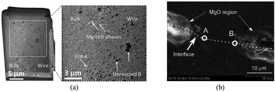
Fig.9.The reported microstructure of the joints fabricated using IMD-processed MgB2 conductors.(a) Patel et al.Reprinted with permission from [38].©ACS.(b) Matsumoto et al.Reprinted with permission from [37].©IEEE.
Fig.9(b) demonstrates the microstructure of a joint fabricated using IMD-processed MgB2wires by Matsumoto et al.A large amount of unreacted B phase was detected which implies incomplete diffusion of Mg into B.The low volume fraction of MgB2supports this conclusion.Other than low MgB2content,a non-superconducting phase(MgO)was also formed beside the MgB2phase.This phenomenon suggests the heterogeneous reaction occurred during the formation [37].Additionally,large cracks were found where two wires were connected.All these negative impacts on microstructure reduce theIcperformance significantly.However,the resistance reported for this joint was only half the value reported by Patel et al.[38].Like the joints fabricated usingin-situMgB2conductors,impurities and cracks did not increase resistance.
4.3.Summary
Comparing the microstructure of thein-situand IMD interface,it can be observed that the IMD intermediate bulk is more condensed than thein-situbulk.However,more nonsuperconducting phases including MgO and unreacted Mg and B are detected from the IMD intermediate bulk.It can be concluded that a condensed microstructure with a smooth interface and less non-superconducting phase can be carried out in future research.
5.Persistent-mode MgB2 coils and magnets
The first PM coil was reported by Takahashi et al.in 2005,but the superconducting joints were fabricated between MgB2and NbTi conductors [39].Another PM coil operated in solid nitrogen (SN2) was reported by Patel et al.[40].A joint ofin-situmonofilament C-doped MgB2wires was fabricated to connect the superconducting coil with the PCS (shown in Fig.10(a) and (b)).This PM coil could operate in solid nitrogen (SN2) at 20 K.The measured resistance was less than 7.4 × 10⁻¹⁴Ωat 19.5 ± 1.5 K for 4.75 days which is within the required resistance range for MRI application.
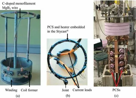
Fig.10.Photos of a PM coil and a PM magnet.(a) and (b) Photos of a PM coil fabricated by Patel et al.(c) A photo of a PM magnet fabricated by Ling et al.Reused with permission from [40,49].©IOP.
In 2016 Ling et al.first time reported a persistent-mode MgB2magnet and proved the feasibility of MgB2for MRI magnet application [49].A photo of the PM magnet is shown in Fig.10(c).Monofilamentin-situMgB2wires were used to wound this magnet.Moreover,since the technology of MgB2was not mature,modules of MgB2coils were joined to minimise the risk of using a single magnet which requires a quite long MgB2conductor.With modularization,the coils were connected by a superconducting joint,so the replacement of coils can be applied if one or more coils failed [49].Besides,a uniform magnetic field can also be achieved by using modularisation.Solid nitrogen (SN2) was used as the cryogen because SN2has larger thermal conductivity than LHe between 10– 13 K and the ability to provide a uniform temperature environment.Furthermore,to protect the magnet from quenching,PCS in each module had an additional function of absorbing excess magnetic energy [50].
In 2020,Choi et al.reported a test coil towards the development of a tabletop 1.5-T osteoporosis MRI.The schematic drawing and photographs are shown in Fig.11.This coil achieved a decay rate of less than 0.6 ppmh-1and resistance of<1.79 × 10⁻¹²Ωat 6 K in self-field.The coil was cooled using SN2[41].With the joint technology created by Kim et al.in 2021,an MgB2magnet was built with a PCS to operate at 10 K.A magnetic field of 352.6 mT was maintained for 46 h and the calculated resistance of the joint was less than 10-11Ωat 10 K [33].
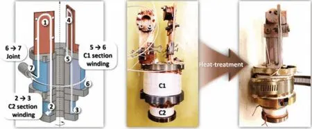
Fig.11.A schematic drawing and a photograph of the test coil built by Choi et al.,reused with permission from [41].©IOP.
Currently,the development of a persistent-mode MgB2magnet for MRI application is still facing challenges in potentially replacing the Nb-Ti magnet.The critical issues of MgB2magnets are the cost of the MgB2wires and high-performance superconducting joints for persistent-mode operation.Therefore,both issues should be simultaneously addressed to make MgB2more favourable for MRI application to replace Nb-Ti which has drawbacks related to premature quenches and the requirement to use LHe.However,the recent development of Freelium and BlueSeal technologies to reduce the active amount of LHe in an MRI system has made the MgB2path more difficult to utilise in MRI in the near future.
6.Concluding remarks
This literature summarised the development of MgB2superconducting joining technologies and persistent-mode magnets to date.Different joint structures and fabrication processes are discussed.The performance of each joint made was collected and analysed.Joint fabrication between reacted MgB2conductors is challenging since their superconducting performance depends on microstructure and composition.It is known that recrystallization and heating of reacted MgB2wires is not an effective route to make high-quality superconducting joints as the melting point of MgB2is high which will cause MgB2to decompose into non-superconducting phases.Cold welding by applying high pressure is also not suitable as MgB2is a brittle ceramic.Therefore,the most promising route for fabricating high-performance joints is to form an intermediate bulk between two wires.This method can be used for both reacted or unreacted mono or multifilamentary MgB2wires.However,superconducting joints for unreacted wire show better performance than joints of reacted wire.As data summarised in Section 3,joints of reacted wires fabricated by Luo et al.showed anIcvalue of 51 A in a self-field at 20 K which is much lower compared to other joints of unreacted monofilament wires [36].Kim et al.have managed to improve the joints of unreacted wires to 167.5 A at 10 K in a 4 T field with a CRR even higher than 100% by sintering at a temperature (600 °C) below the melting point of Mg (650°C) for a long period (4 h) [33].Although the performance of joints of reacted wires is lower,they are practicable for MRI magnets application.It can be concluded that the joint structure shown in Fig.2(b) is the most promising for highperformance joints of MgB2conductors.Microstructural observation showed that impurities,non-superconducting MgO phase,unreacted Mg and B,and cracks in the microstructure can depress theIcof the joint since the intergranular connectivity is weakened.However,these factors only had a slight influence on the resistance of joints.Lastly,the development of a persistent-mode MgB2magnet is summarised.Currently,the critical issues of MgB2magnets to enter the MRI magnets market are the cost of the MgB2wires and high-performance superconducting joints for persistent-mode operation.Formation of intermediate bulk by IMD process can be considered a feasible approach since a CRR of almost 100% and superconducting joints of reacted wires can be obtained[38].In the future of MgB2joints for MRI application,high-performance joints of reacted multifilament wires are the ultimate goal.Joints of reacted conductors will be more feasible for MRI magnets construction compared to joints of unreacted conductors.
Declaration of competing interest
The authors declare no competing financial interest.
Acknowledgement
We are thankful for the support from the Australian Research Council (ARC) Linkage Project (LP200200689).This work used the Queensland node of the NCRIS-enabled Australian National Fabrication Facility (ANFF).Part of this manuscript was organised by Dipak Patel while working at the University of Queensland.
 Journal of Magnesium and Alloys2023年7期
- Journal of Magnesium and Alloys的其它文章
- “Smart” micro/nano container-based self-healing coatings on magnesium alloys: A review
- Recent advances using equal-channel angular pressing to improve the properties of biodegradable Mg–Zn alloys
- Twin evolution in cast Mg-Gd-Y alloys and its dependence on aging heat treatment
- Effects of Ce content on the modification of Mg2Si phase in Mg-5Al-2Si alloy
- Solute drag-controlled grain growth in magnesium investigated by quasi in-situ orientation mapping and level-set simulations
- Formation and growth of precipitates in a Mg-7Gd-5Y-1Nd-2Zn-0.5Zr alloy aged at 200 °C
