Influence of tool rotational speed on mechanical and corrosion behaviour of friction stir processed AZ31/Al2O3 nanocomposite
Ashish Kumr ,V.P.Singh ,Akhilshwr Nirl ,R.C.Singh ,Rjiv Chudhry ,Adl-Hmid I.Mourd ,B.K.Shoo,Dpk Kumr
aDepartment of Mechanical Engineering,Delhi Technological University,Delhi 110042,India
b Department of Mechanical Engineering Galgotias College of Engineering and Technology,Greater Noida 201310,India
cDepartment of Mechanical Engineering,National Institute of Technology Mizoram,Aizawl 796012,India
d Department of Mechanical Engineering,IES College of Technology Bhopal,462044,India
eMechanical and Aerospace Engineering Department,College of Engineering,United Arab Emirates University,Al-Ain 15551,United Arab Emirates
fMaterials Engineering Division,CSIR -National Metallurgical Laboratory (NML) Jamshedpur,831007,India
g Department of Mechanical Engineering,Carnegie Mellon University,Pittsburgh,PA 15213,USA
Abstract Nano-sized reinforcements improved the mechanical characteristics efficiently by promoting more implicit particle hardening mechanisms compared to micron-sized reinforcements.Nano-sized particles lessen the critical particle solidification velocity for swamp and thus offers better dispersal.In the present investigation,the friction stir processing (FSP) is utilized to produce AZ31/Al2O3 nanocomposites at various tool rotation speeds (i.e.,900,1200,and 1500 rpm) with an optimized 1.5% volume alumina (Al2O3) reinforcement ratio.The mechanical and corrosion behavior of AZ31/Al2O3-developed nanocomposites was investigated and compared with that of the AZ31 base alloy.The AZ31 alloy experienced a comprehensive dynamic recrystallization during FSP,causing substantial grain refinement.Grain-size strengthening is the primary factor contributed to the enhancement in the strength of the fabricated nanocomposite.Tensile strength and yield strength values were lower than those for the base metal matrix,although an upward trend in both values has been observed with an increase in tool rotation speed.An 19.72% increase in hardness along with superior corrosion resistance was achieved compared to the base alloy at a tool rotational speed of 1500 rpm.The corrosion currents (Jcorr) of all samples dropped with increase in the rotational speed,in contrast to the corrosion potentials (Ecorr),which increased.The values of Jcorr of AZ31/Al2O3 were 42.3%,56.8%,and 65.5% lower than those of AZ31 alloy at the chosen rotating speeds of 900,1200,and 1500 rpm,respectively.The corrosion behavior of friction stir processed nanocomposites have been addressed in this manuscript which has not been given sufficient attention in the existing literature.Further,this work offers an effective choice for the quality assurance of the FSP process of AZ31/Al2O3 nanocomposites.The obtained results are relevant to the development of lightweight automobile and aerospace structures and components.
Keywords: Friction stir processing;AZ31 alloy;Al2O3;Nanocomposite;Mechanical properties;Corrosion resistance.
1.Introduction
Magnesium (Mg) and its alloys have drawn a lot of interest for several industries,including automotive,aerospace,and electronics,in the last few decades [1].Due to their numerous attractive attributes,such as lightweight and good specific strength,these alloys are in higher demand[2,3].The AZ31 is most frequently used alloys in the AZ-series,and around 70%of Mg cast products are made from this alloy[4,5].Numerous researchers have investigated various materials,including carbon nanotubes (CNTs) [6],alumina (Al2O3) [7,8],graphene nanoplatelets [9],silicon carbide (SiC) [10],zirconium oxide(ZrO2) [11],and yttrium oxide (Y2O3) [12],as reinforcement for Mg metal matrix composites (MMCs) by utilising a variety of fabrication techniques.Interest in Al2O3,SiC,and other carbonaceous nanoparticles has increased very recently,and considered to be an emerging type of reinforcing material that is utilized to improve different physical,mechanical,and corrosion characteristics in MMCs [13].
At present,spray deposition [14],stir casting [15],powder metallurgy [16],in-situfabrication [17],and laser based additive manufacturing [18,19],are the primary techniques of MMCs’ development.However,the composites produced using the aforementioned techniques have a number of issues,including solidification flaws,fractures,and an uneven microstructure,which reduce the materials’ strength and flexibility.Severe plastic deformation (SPD) techniques such as forging,extrusion,and rolling might solve the aforementioned issues;however,the procedure is labor-intensive and essentially impractical.In spray deposition method using an airbrush,the irregular dispersion of atomized solution droplets results in the formation of irregular menisci.These abnormalities are expected to generate surface roughness profiles with height differences of hundreds of nanometres or more between peaks and valleys [20,21].Sajjadi et al.[22]employed stir casting to develop Al–Al2O3micro and nanocomposites and conveyed a poor integration of Al2O3in the melt.After the development of MMC,the reinforcement particles were treated with heat to avoid these difficulties.Hence,it can be concluded that stir casting offers a number of benefits,such as a simple and economical method,but suffers from a number of drawbacks,including inhomogeneous dispersion of reinforcing particles,excessive porosity,and lack of particle wettability by molten metals [23].Moreover,Zhang et al.[24]investigated the effect of minor Ag addition on the microstructure and characteristics of powder metallurgy (PM)of Cu-10 wt.% Fe alloy.PM has been demonstrated to be an excellent way for refining various phases [24,25]when compared to the conventional casting technique.Finding an effective preparation method is a crucial and formidable challenge if one wants to overcome these issues and produce Mg matrix composites with high formability and performance.Nevertheless,because of the significant Van Der Waals forces,it has always been difficult to evenly distribute nano-size reinforcements in MMCs [26].
To achieve uniform dispersion of the nanoscale Al2O3particles in the matrix of MMCs,researchers and scientists have attempted to fabricate the MMCs with a number of techniques,including ultrasonic-assisted stir casting,ball milling,surfactants,and chemical coatings.Nevertheless,these techniques did not improve the dispersion of nanoparticles in MMCs effectively,and thus,the need for a viable process arises [27–30].During the FSP process,the tool’s rotational speed plays a crucial role in the frictional heat input in the processed zone.As per Peel et al.[31]on welding of 3 mmthick AA5083 and AA6082 alloys through friction stir welding (FSW) method,the tool rotational speed has shown more impact on heat input compared to transverse speed [32,33].Bagheri et al.[34]investigated the AZ91/SiC surface composite layer generated by vibration assisted friction stir vibration processing (FSVP).As FSVP was applied,the results demonstrated that the microstructure was improved and mechanical characteristics such as ductility,hardness,and strength were enhanced [34–37].FSVP nanocomposite layers feature finer microstructures than FSP nanocomposite layers,and nanosized particles are distributed more uniformly.The effect of vibration during FSVP,which led to an increase in material deformation,accelerated dynamic recrystallization,and the disintegration of agglomerated SiC particles.In the same investigation,the corrosion resistance of FSVPed samples was significantly higher than that of standard FSP and the base material [31–33].
Until far,the majority of FSP research has been on enhancing the mechanical properties of the material,with little emphasis paid to examining the effect of tool rotating speed on the mechanical and corrosion behavior of Mg alloys during FSP.The corrosion behavior of Mg alloys is primarily determined by a number of parameters,such as microstructure,material composition,exposed environment,and the properties of the film generated during operation.To the best of the authors’ knowledge,no detailed investigation has been undertaken on the influence of FSP parameters,such as tool rotational and linear speed,as well as the number of FSP passes,on the mechanical and corrosion behavior of AZ31 Mg alloy through FSP.A comprehensive investigation into the particle distribution and matrix grain size is included in the present work.Overall,the effects of Al2O3and tool rotation speeds on the mechanical,corrosion,and microstructural evaluation of composites are explored in depth,which will be extremely beneficial for a variety of industrial applications.Therefore,the main objectives of this work is to investigate the mechanical and corrosion behavior of AZ31 Mg based nanocomposites through FSP.In addition,this work offers an effective choice for the quality assurance of the FSP process of AZ31/Al2O3nanocomposite.
2.Experimental procedure
2.1.Materials and preparation
AZ31 is mainly composed of Mg,as well as a small amount of Al (2.8–3.2 wt.%),Zn (0.7–1.3 wt.%),and Mn(~0.2 wt.%) and nano Al2O3particles with mean diameters of 40 nm were used in this investigation.The comparison between micro-sized Al2O3 particles and nano-sized Al2O3 particles revealed minimal impact on the results,except for the ductility aspect.Consequently,the focus of the experiments was placed solely on the nano-sized particles.The plates dimensions (100 mm × 80 mm × 6 mm) were machined from ZE31 cast billet.Fig.1(a) depicts TEM characterization images of nano Al2O3powder,while Fig.1(b)and (c) are the SEM characterization of micro Al2O3powder and corresponding EDS map respectively.The preliminary testing’s indicated that enforcement of micro-size particles increased the strength,but reduced ductility.Therefore,no further study has been performed on micro-size enforcement composites.On the other hand,nanocomposites showed a good balance of strength and ductility,and thus considered for further investigations.On each plate,4 mm diameter holes were drilled up to 3.6 mm in depth.The well-mixed,99.9% nano-size (40 nm average particle size) Al2O3particles were then used to fill these holes.The volume fraction(1.5 vol.%) of Al2O3particles was chosen for each sample as per the previous study [38].To avoid Al2O3particles from being ejected from the groove during FSP,the groove surface was first sealed using a pin-less tool (columnar probe with thread).The schematic of FSP process,nano Al2O3powder,workpiece with grooves,and workpiece after FSP are shown in Fig.2.(a-d),respectively.After several experiments,the tool’s rotating speed and traverse speed were optimized to be 900,1200,and 1500 rpm and 50 mm/min,respectively.

Fig.1.Characterization of Al2O3 powder (a) transmission electron microscopy (TEM) image for nano-sized Al2O3 (b) scanning electron microscope (SEM)image for micro-sized Al2O3,and (c) elemental composition obtained using energy dispersive spectroscopy (EDS) method.
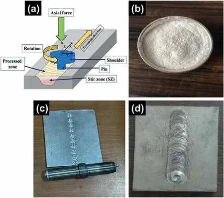
Fig.2 (a).A schematic of FSP process,(b) nano Al2O3 powder,(c) workpiece with groves,and (d) workpiece after FSP.
Table 1 includes the FSP parameters.The FSP was executed with two number of passes (referred as 2P).The second pass was performed in opposite direction to the first pass to enhance the material intermixing.By developing three distinct sample types,it was feasible to better comprehend how nanoparticles affect grain size.For sample preparation,a threaded tool with 4 mm pin length and 20 mm shoulder diameter was used.The FSP process parameters were selected based on the existing literature [34,35],and pre-trial experimentation.Then,an optimised set of parameters were taken into consideration.The first sample (designated as AX0) had no reinforcement and processing,whereas,second,third and fourth sample (designated as AX1,AX2,and AX3) were processed at 900,1200 and 1500 rpm,respectively,with a consistent volume percentage of nano Al2O3powder.The samples were mechanically performed after mounting them in transverse section.Using optical microscopy (OM) and SEM,the distribution of Al2O3particles and the grain size of the etched sample were examined.

Table 1FSP parameters for the experiment.
2.2.Microstructure characterization
The metallographic characterization was accomplished on both composites as well as base metal samples.The samples were cut perpendicular to the processing direction in 15 mm × 5 mm × 3 mm dimension.The samples surfaces were ground with 400,1000,2000,and 5000 grit silicon carbide (SiC) emery papers,and mirror finish polishing was achieved by using the diamond paste (super fine 0–1/5 μm).The samples were etched for 10 s using a solution of picric acid (10 mL acetic acid,10 mL water,and 4.2 g picric acid mixed in 100 mL alcohol) to reveal the microstructure.The microstructures were examined using OM(Leica-DM2500M),SEM ((Zeiss Supra 40) inbuilt with EDS system.
2.3.Mechanical properties
Using a microhardness tester with a standard load of 100 g and a dwell time of 15 s,the microhardness tests were conducted.The tensile specimens (34 mm in length,8 mm in breadth,and 3 mm in thickness) as per the standard of GB/T 228.1–2010 were cut along the transverse direction,and subsequently grounded and polished.The tensile characteristics were examined at room temperature using universal testing machine (UTM) machine (Model: Instron,8862) with crosshead speed of 1 mm/min and at a constant strain rate of 1.0 × 10⁻³s-1.Each set of samples was tested at least three times for reproducibility and good statistics.
2.4.Corrosion test
Computer numerical control (CNC) wire electrical discharge machining (EDM) (Elektra,Maxicut 523) was employed to cut the specimens for the corrosion testing exclusively from the agitation zone in the centre of the FSPed samples.Potentiodynamic polarization and electrochemical impedance spectroscopy (EIS) were two of the techniques used to examine the corrosion behavior.To analyze the electrochemical corrosion process,a three-electrode system was constructed using platinum as the counter electrode,Ag/AgCl as the reference electrode,and FSPed specimens as the working electrode.The specimens’ other side was exposed to the corrosive solution,and a cold-setting resin wire which was associated to the electrodes.Following one hour of exposure to a 3.5% NaCl solution at room temperature,the specimens were subjected to EIS tests using a potentiostat/galvanostat with a frequency response analyser (FRA).
3.Results and discussions
The MMCs have been successfully fabricated using FSP technique by reinforcing nano Al2O3powder in AZ31 Mg alloy matrix.The three composite samples and one monolithic sample were fabricated at 900,1200 and 1500 rpm,while,keeping all other parameters constant.The samples were characterised and consequently tested for mechanical (hardness and tensile test),and corrosion behavior.
3.1.Microstructural characterization
It is generally known that a variety of factors,including as temperature,strain,and strain rate,influence the evolution of the microstructure during the FSW process.In the FSW process,only the temperature affecting grain growth is measured,hence the variation in nucleation rate induced by temperature during the nucleation stage is insignificant.[39–42].Using OM and SEM,monolithic and nanocomposite specimens prepared at different rotational speeds are characterized to investigate grain refinement,surface morphology,and reinforcement dispersion in the surface composite.Fig.3(a-b) shows the macrostructure and microstructure of an FSPed AZ31 alloy with the basic metal (BM),stir zone (SZ),heat-affected zone (HAZ),and thermo-mechanically affected zone (TMAZ).The microstructure analysis revealed no major defects in the composites.Theα-Mg matrix andβ-phase(Mg17Al12) particles are dispersed along the grain boundaries in base material.Clearly,increasing the rotational speed will increase the grain size.It may be associated with both continuous and occasional recrystallizations that occurred during substantial deformation.During this process,many lowangled grain boundaries (LAGBs) are formed,which are then transformed into high-angled grain boundaries (HAGBs) by continuous dynamic recrystallization (CDRX).Discontinuous dynamic recrystallization generates novel grains at preferred sites (DDRX) [43,44].
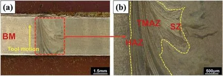
Fig.3 (a).FSPed macrostructure of monolithic alloy AX0 (b) FSPed microstructure of monolithic alloy AX0 indicates HAZ,TMAZ,and SZ.
Those samples with major defects were not consider for further study as they failed in preliminary inspections.Due to high rotational speed,high strain rate and frictional heat generation are produced in SZ.Fine grain microstructures in this region are produced due to DRX.Fig.4(a-d) depict OM images of the monolithic and SZ of the FSPed composites at various tool rotating speeds.The particle distribution was very consistent across the entire stir zone,and the cross sections of the samples did not clearly reveal any voids in the stir zone.Small macro-defects were seen in the SZ of the sample processed at 900 rpm,as depicted in Fig.4(b).Other samples(Fig.4(b-d)),however,showed no macro-defects,which was mostly because material flow was improved at higher rotating speeds.Also,the samples at 900 and 1200 rpm showed onion ring patterns(Fig.4(b&c)),The 1500 rpm samples,however,did not reveal any onion rings (Fig.4(d)).This band was formed due to the material flow from the warmer top zone to the cooler bottom zone.When the heat input is insufficient,the material flow is poor,making it impossible to construct an onion ring.According to Krishnan’s findings [45]for the FSW of 6061 and 7075 alloys,the onion ring layers were spaced apart by around 45 and 37 μm in samples at 1200 and 1500 rpm rotational speeds,respectively.This value is equivalent to the proportion of forward motion to rotation speed.

Fig.4.Optical metallographic image of (a) monolithic alloy AX0,and (b-d) composite specimens (AX1-AX3),respectively.
Fig.5(a-b) show the grain orientation distribution maps for the monolithic alloy and AX2 specimens,respectively.According to Fig.5(a),BM has equiaxed grains ranging in size from 0.19 to 43.5 μm,with a mean grain size of 8 μm.In the AX2 sample,which has a size range between 0.4 and 15 μm,the average grain size is refined to 7.6 μm when compared to the BM (Fig.5(b)).The small color dots in the EBSD map(Fig.5(a&b))is unindexed areas.The AX3 sample has a more homogenous and refined microstructure than the AX2 sample,with grains that range in size from 0.1 to 10 μm and with a mean size of 4.1 μm.With an increase in tool rotation speed,the cumulative refinement influence increases,causing coarse grains to be smashed and grains to be significantly refined.The lower right corner of the AX2 specimen exhibits glaring voids and agglomerations (Fig.5(b)).By FSP’s stirring effects and material mobility,particles become homogenous.As for AX2,this implies that as FSP stir effects and material flow grow,the alumina particles are mixed with the Mg matrix to a greater extent.Fig.5(c-f) shows the EDS elemental maps of the monolithic alloy and composite AX2 samples.
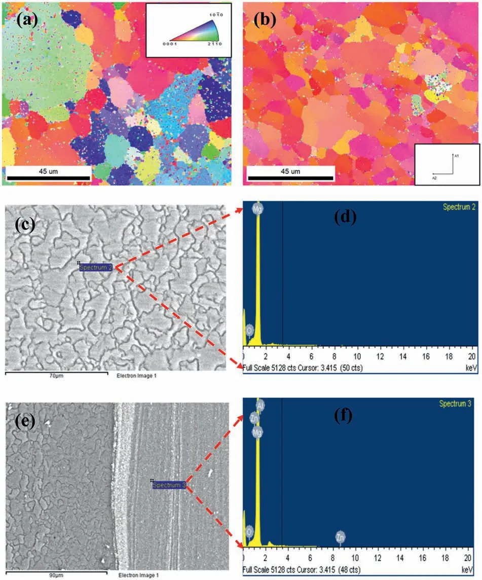
Fig.5.The grain orientation distribution of (a) monolithic alloy,and (b) composite AX2 specimen,(c) and (e) represent SEM microstructure and the corresponding location of EDS point analysis mentioned in (d) and (f) respectively.
The development of fine grains may be connected with DRX as the number of passes increases [46].DRX arises commonly during FSP because of high temperatures and distortion.The grain size is refined through DRX.As the number of passes increases,the value of grain size falls[46,47].Fig.6(a) depicts the SEM microstructure of asreceived monolithic AZ31 Mg alloy.The microstructure of AZ31 is characterized by a coarse eutecticβ-Mg17Al12precipitates network dispersed at the grain boundaries(Fig.6(a)).The Mg-Al phase diagram indicates that the eutectic-Mg17Al12phase dissolves around 420 °C -450 °C into the matrix of Mg.Accomplish the eutectic-Mg17Al12phase’s full dissolution due to the Mg matrix’s low rate of aluminium diffusion [48].FSP during stirring involves rapid colling and heating.The complete dissolution of reinforcement seems to be impossible,the eutectic-Mg17Al12phase for a Mg alloy occurs for a very small span of thermal cycle time.The dissolution of the Mg17Al12phase is substantially assisted by 0.4%,resulting in an aluminium-supersaturated solid solution.However,the SZ underwent significant plastic deformation with strain rates ranging from 10-2to 10-3s-1and a strain up to the dissolution of the Mg17Al12phase.

Fig.6.SEM microstructure of (a) monolithic AZ31 alloy,(b) composite sample (AX1),(c) composite sample (AX2),and (d) composite sample (AX3).
The dissolution of the coarse precipitated phase is anticipated to increase the ductility and formability of the FSPed AZ31 alloy,which has a fine and uniform grain structure[49].After the appropriate polishing and subsequent etching process,the SEM images at 200 X were captured for all three sets of composites developed at 900 rpm,1200 rpm,and 1500 rpm,as shown in Fig.6(b-d),respectively.The monolithic specimen (AX0) with a rotation speed of 900 rpm,as shown in Fig.6(a),exhibits insufficient heat production,resulting in the formation of numerous large cracks.The insufficient heat generation in the processed zone,due to the low rotating speed,resulted into agglomerations of alumina at different locations that can be seen together with cracks;it is difficult to differentiate the presence of alumina in this zone.The effect of heat input on the SZ,as well as the mixing of reinforcement in the matrix,are shown in Fig.6(b).Although heat generation enhanced,this mixing is still inadequate to disperse the reinforcements in the matrix.At lower rotational speed,i.e.,900 rpm,formation of voids occurs due to inadequate heat input,whereas the Al2O3reinforcements are distributed more evenly across the matrix at higher rotational speeds i.e.,1200 and 1500 rpm as shown in Fig.6(c&d).In addition,the existence of significant populations of graphene agglomerations in particular sites enhance the possibility that nearby cracks may begin to form.This is also linked to a faster rate of fracture propagation due to the agglomeration at the grain boundaries settles,which decreases ductility [50].The potential of nanoparticles to influence the mechanism of fracture propagation due to crack spanning,deflecting,and branching was already mentioned in other study as well [51].Dynamic recrystallization (DRX) is the nucleation of new grains,and their growth.Along the elongated grain boundaries of the deformed material,the grains may nucleate uniformly or randomly.During the DRX procedure,grain growth tends to drive the cluster of reinforcing material formed along the grain boundaries.
Under lower stress levels,these inaccessible clusters of nano-powder cause cracking and also produce a low-energy channel for the propagation of cracks at the grain boundaries[52].The presence of uniformly scattered Al2O3particles in a composite layer led to a severe grain refinement.In addition to the grain refinement brought on by the severe plastic deformation (SPD) that take place in the SZ,the matrix grain refinement in the case of FSP with Al2O3reinforcement can be ascribed to the combined effects of:(i)the ability of Al2O3reinforcement to nucleate Mg grains during recrystallization;and (ii) the constrained growth of recrystallized Mg grains by means of the presence of Al2O3reinforcement (the pinning effect of Al2O3reinforcement) [53].
Because nanoparticles have a uniform distribution at a fixed volume fraction,an expanding grain boundary faces numerous obstacles as it attempts to migrate.The placement of nanoparticles and their clusters along the grain boundaries prevented grain growth.As previously mentioned,there is some clustering of nanoparticles in Fig.6(c),nonetheless,the proportion of large clusters relative to small clusters (<90 nm) is minimal.On the triple junction or at grain boundaries,clustered Al2O3is shown in Fig.6(b),and some Al2O3is also embedded in the grains of the matrix.As can be evident,Al2O3cluster size decreases with each FSP pass and with increase in tool rotation speed.
3.2.Hardness test
Fig.7 shows the impact of Al2O3particle addition and tool rotation of the FSP on the average microhardness of the AZ31 base alloy and developed nanocomposites.It can be noticed that the microhardness of the AZ31 alloy is improved by the addition of Al2O3particles and nearly doubles for the AZ31–10% Al2O3composite.This is owing to the fact that Al2O3particles have a high hardness and also block the dislocations motion.The average microhardness of the cast base alloy is 76 HV which is basically due to the coarse grains in the microstructure.However,following FSP,the microhardness value increases to 119 HV.This is because the development of fine grain microstructure during FSP leads to the refining of grains in the SZ owing to DRX.Due to the ultra-refinement of the grains by the grain boundary pinning process,the inclusion of reinforcement particles at the SZ further increases the hardness [54,8,55].Different microhardness values were obtained for different composites samples and base metal in various zones.The possible reasons are the Al2O3inclusion in the AZ31 alloy,severe plastic deformation(SPD) in the SZ,the pinning phenomena at the grain boundaries,DRX,along with variation in tool rotation speed.On the other hand,as can be observed in the sample processed at 900 rpm,the particle strengthening effect was reduced,and the composite hardness was nearly equal to matrix hardness.This may be attributed to the poor particle dispersion conditions.Second-phase particles and fine grains contribute to greater levels of hardness [46].
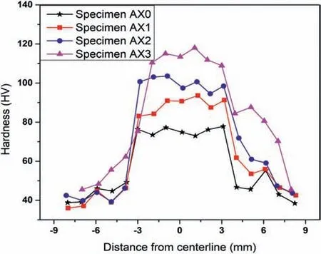
Fig.7.Microhardness of monolithic and composite specimens measured from the centreline.
3.3.Tensile test
Uniaxial tensile tests on the samples before and after FSP were carried out in order to investigate the effect of the nanoalumina addition at different tool rotation speeds on the tensile properties.For good statics,three samples from each set of parameters were selected for the tensile test,and the average data is reported.A summary of the tensile response/properties is tabulated in Table 2.The engineering stress and engineering strain diagram curves are shown in Fig.8(a).The alterations in the yield strength (YS),ultimate tensile strength(UTS),and percentage elongation (EI)are shown in Fig.8(b).It was evident that the monolithic alloy had an inhomogeneous microstructure(Fig.6(a))and exhibited a yield strength of 112.78 MPa with slightly less elongation.After FSP,the elongation increased significantly,and it was nearly two times greater than that of the BM but the yield strength abruptly dropped to 67.43 MPa,or roughly half of the BM.

Table 2Summary of tensile properties.
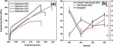
Fig.8.(a) Engineering stress and engineering strain diagram of monolithic alloy and composites (b) variation in UTS,YS and percentage elongation.
The formation of a tilted basal texture after FSP has been frequently reported in various studies in the past [28,49,56].In order to accommodate the applied strain during the tensile test,simple deformation modes with a lower critical resolved shear stress (CRSS),such as basal slip and tension twinning,were heavily active.The yield strength dramatically dropped due to the activation of these deformation modes.Strain localization occurs during tensile tests as a result of FSW,generating a favorable crystallographic structure for basal slip close to the weld zone’s edge but limiting it in the weld zone’s centre [42,47].Hence,it is believed that strain localization accounts for the lower elongation values of welded Mg joints(in comparison to those of the as-received AZ31B).
When compared to the AZ31 Mg matrix,the reinforcing particulates strength is superior.To yield the Mg matrix,additional force is required to fracture the clusters.However,clusters and inappropriate distribution are inconsequential for enhancing the UTS after crossing the yield threshold.After yielding,the clusters do not permit load transfer.As a result of the reinforcing particulates distribution being progressively clustered,the UTS of MMCs decreases with an increase in tool rotational speed.Clustering distribution of reinforcement leads to premature failure,decreased the tensile strength and ductility of the developed composites.With the increase in tool rotational speed,grain refinement results in a little rise in tensile strength and a slight reduction in percentage elongation in the FSPed for sample AX1 and AX2[57].However,at higher rotational speeds,the Al2O3reinforced MMCs exhibit a notable improvement in tensile performance.The dispersion of Al2O3particles was improved with the increase in rotational speed,providing sufficient resistance to withstand the tensile force.The enhanced reinforcing particles distribution increased material flow and reduced early fracture,which in turns resulted in the increase composite specimens’ elongation.However,following FSP,the grain size was drastically reduced,resulting in a more homogenous plastic deformation and an increase in ductility.The increase in strength is based on a number of strengthening mechanisms,including the Taylor’s equation,the Hall-Petch strengthening,and the Orowan strengthening mechanism [58,59].
The fracture surfaces of a few selected tensile failure specimens are shown in Fig.9(a–d).Monolithic alloy’s fracture surface (Fig.9(a)) exhibits a high number density of welldeveloped dimples,which indicate ductile mode of fracture.The dimples are also seen in all other samples which demonstrate that the fracture is ductile for nanocomposites as well(Fig.9(b-d)).Sample AX1 fails rapidly because the clusters and sintered zone shatter before the dimples completely form.On the other hand,the uniform dispersion of Al2O3particles resulted in the formation of well-shape dimples.A considerable number of dimples exhibiting ductile mode of failure suggests that there is a strong interfacial bond between the matrix and the Al2O3particles.

Fig.9.(a-d) Fracture morphology of (a) monolithic AZ31 alloy,(b) composite sample (AX1),(c) composite sample (AX2),and (d) composite sample (AX3).
3.4.Corrosion test
The Nyquist and Bode graphs from monolithic and FSPed composites samples immersed in a 3.5% NaCl solution for 1 h at various conditions are shown in Fig.10(a-c).Nyquist graphs (Fig.10(a)) for the base metal with two-pass FSPed processing reveal two-time constants that correspond to the occurrence of capacitive and inductive loops,respectively,in high and low frequency scales.The Bode charts for the FSPed samples and monolithic alloy seem to agree with the Nyquist maps.
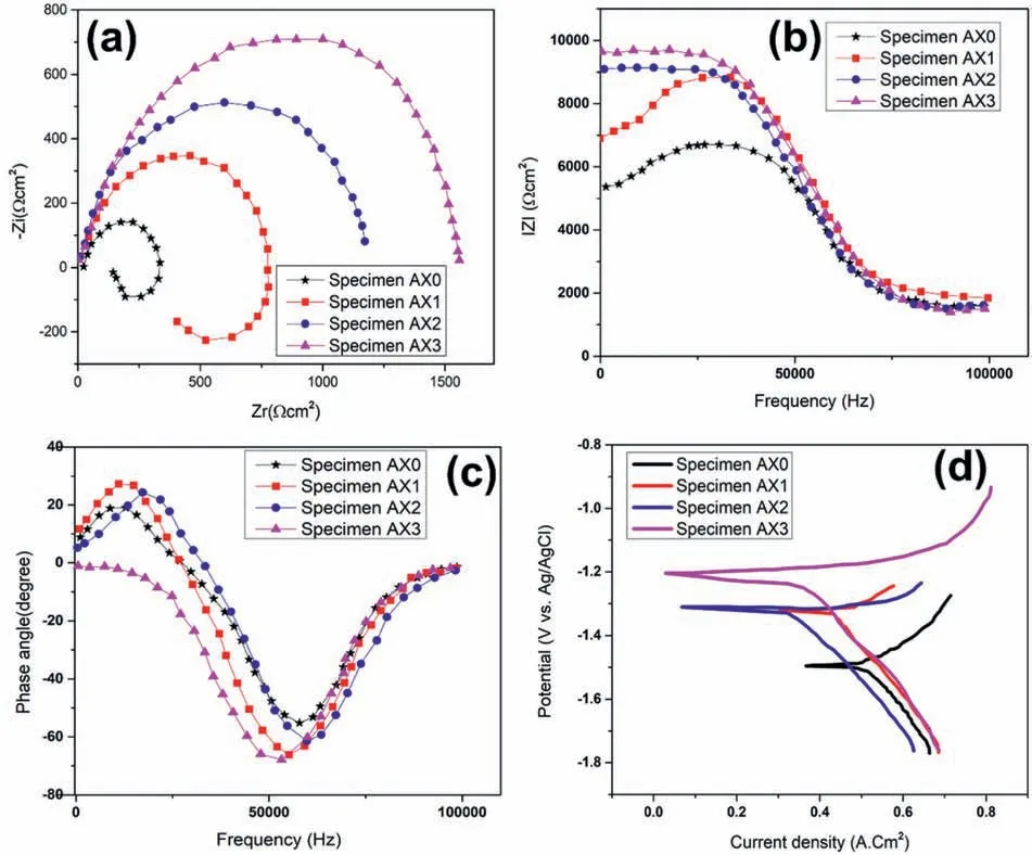
Fig.10 (a-c).Nyquist and Bode plot for monolithic alloy and composite specimens,(d) polarization curve for monolithic alloy and composite specimens.
From high to medium frequencies,the capacitive loop is triggered by the electrode’s charge transfer resistance.It should be noted that charge transfer resistance is closely correlated with the capacitive loop’s width.Pitting corrosion like Mg(OH)2or Mg(OH)ads+might be the cause of the inductive loop’s existence [60,61].Higher charge transfer resistance,or improved corrosion resistance is indicated by the bigger capacitive loops’ diameter in the FSPed composites compared to the base metal.The capacitive loops’ diameter for the composites reduced as tool rotational and traverse speeds increased,resulting in low corrosion resistance.An inductive loop and a capacitive loop are clearly present in the samples of the base metal and developed nanocomposites.According to certain reports,the existence of an inductive loop in Nyquist maps indicates surface corrosion(localised corrosion,particularly pitting).Hence,the lack of an inductive loop is evidence that corrosion is better controlled [62].
The diameter of the capacitive semicircle in the EIS spectra’s Nyquist maps was strongly associated with the ability to resist corrosion.Corrosion resistance is higher in the specimens with bigger capacitive semicircle diameters in the Nyquist plots of EIS spectra.The plots showed that AZ31 composites produced at higher rotating speeds had wider capacitive arcs,despite the samples’ identically shaped curves.This demonstrated that higher rotational speeds improved corrosion resistance,confirming the findings of earlier analysis.According to the aforementioned findings,greater rotational speeds would increase the likelihood that AZ31/Al2O3with superior corrosion resistance would be produced,providing that all other conditions remain constant.
As per the general corrosion reaction occurs in aquatic environments of Mg -which typically includes the electrochemical interaction of Mg and water to develop Mg(OH)2and H2as described by other researchers [62–64],the EEC (electrical equivalent circuit) was established.ZViewfi programme used the proposed EECs to analyze the impedance data,and the outcomes are tabulated in Table 3.Owing to the high electrical conductivity of NaCl solution,the values of Electrical resistance of solution (Rs) are practically identical and relatively low.The charge transfer resistance (Rct) values for the composites are much greater than the base metal.As stated in Table 3,processing parameters of 50 mm/min and 1500 rpm resulted in the highest corrosion resistance for the developed composites.Increase in rotational speed,resulted in a drop in the Rctvalues for the 2-pass composites.Even though the traverse speed increased and the grain size reduced,the Rctvalue for the FSPed samples processed at 50 mm/min was higher.High traversal speeds,which might increase residual stresses and diminish the beneficial effects of grain refining,are likely the cause.According to reports [63,64],the corrosion behavior is negatively impacted by residual stresses,a significant number of surface defects,and a high dislocation density or grain boundary density.Additionally,the Rct value dramatically enhanced from 315.45Ωcm2for the base alloy to 1103.21 and 1312.67Ωcm2for the 2-pass when the rotational speed was increased from 900 rpm to 1500 rpm.

Table 3EIS measurements data for monolithic alloy and composites specimens.
The base metal and developed composites polarisation curves are shown in Fig.10(d),together with the electrochemical data intended for use with the Tafel extrapolation method described in Table 4.Each of the FSPed samples’anodic polarisation curves turns in favor of a more noble potential,signifying decreased anodic dissolution that might be attributable to the fine-grained composite structure.

Table 4Details of electrochemical test data obtained through Tafel extrapolation technique.
Due to the spurt of passive film development on the top surface,FSP led to a reduction in the anodic current density as shown in Fig.10(d).In addition to the significant processing effect on the expedition of passive film development on the developed samples,the decrease in catholic kinetics also contributed to the decreased corrosion current density of composites.Table 4 reveals that AX3 has the least polarisation current density as compared to all other samples.The corrosion potential (Ecorr) is reduced by increasing the rotational speed,but the corrosion current density shows no noticeable trend.Similar results were obtained from the corrosion investigation that was conducted on AZ31B and ZK61 Mg alloys at various tool rotational speeds and transverse speeds [65].The cathodic Tafel slope(βc)for the composites is lesser than the base metal,and the value of the cathodic slope declines with a drop in rotation speed from 1500 to 900 rpm.Similar observations have been made in earlier literature as well[64].The anodic Tafel slope for the developed composites is greater than the base metal.Second phase particles or intermetallic compounds are considered to be the cause of the cathodic activity [66,67].
According to electrochemical studies,Fig.10(d) depicts the polarization curves of base metal and developed composites produced at various rotational speeds,as well as the curves of OCP values as a function of the length of time the samples were exposed.The corrosion potential (Ecorr)and corrosion currents density (Jcorr) of the samples were calculated using the Tafel extrapolation technique,and are displayed in Table 4.These values may indicate the difficulty of corrosion initiation and the rate of corrosion as well.With longer soaking times,all samples’ potentials tended to stabilize.AZ31 base alloy exhibited the lowest stable potential (1.571 V) among all the samples,indicating that FSP might reduce the propensity of Mg alloy to initiate corrosion.The stable potentials of FSP AZ31 and AZ31/Al2O3created at higher rotating speed had higher potential values as a result of the Al2O3particles,fine grains and uniform dispersion.The Jcorr of samples dropped with increasing rotating speed,in contrast to the Ecorr,which increased.The Jcorr of AZ31/Al2O3was 42.3%,56.8%,and 65.5% lower than that of AZ31 at the rotating speeds of 900,1200,and 1500 rpm,respectively.AZ31/Al2O3exhibited a lower Ecorr and a higher Jcorr than specimen AX1,indicating that the composite had less corrosion resistance.The primary cause of this event was severe micro-galvanic corrosion that was accelerated by the potential difference.The Jcorr and Ecorr data,however,suggested that AZ31/Al2O3had superior corrosion resistance to FSP AZ31 at 1200 and 1500 rpm.The mixing impact on the matrix drastically improved as rotational speed rose,which helped to create a more even distribution of Al2O3particles.Additionally,more reliable particle distribution might result in a pinning action on many grain boundaries,further refining the grains,as well as more uniform corrosion behavior for composite materials.
The corrosion morphologies of AZ31 and composites samples are depicted in Fig.11(a-d).As can be observed,BM underwent pitting corrosion after 5 h of immersion,however the surfaces of the AX2 and AX3 samples did not exhibit corrosion pits.After 5 h,pitting corrosion also developed in the AX1 sample,increasing the number of corrosion pits in the AZ31 sample.The corrosion area of the monolithic alloys progressively became larger with increasing immersion duration,and after 24 h of immersion,severe corrosion attacked on the surface.The surface of the AX2 and AX3 specimens showed strong corrosion resistance and revealed very thin and uniform corrosion layer.Additionally,it demonstrates that composites have greater corrosion resistance.Several studies have assessed grain size when analysing corrosion,and numerous researchers have proposed that as grain size decreases,corrosion resistance increases.Improved corrosion resistance is typically attributed to the ability of surfaces with high grain boundary density to passivate more readily or to the physical disintegration of second phase intermetallic particles[72].
Fig.12 depicts the XRD patterns of the corrosion samples following a 24 h immersion in a 3.5 wt.% of NaCl solution.Mg(OH)2is found to be the primary corrosion product,and agreeing with the EDS analysis.It has been documented that Mg(OH)2is the primary corrosion product in earlier research studies [65,68].Furthermore,for the FSPed samples,the Mg diffraction intensities from the substrate reduced,which is consistent with the existence of more Mg(OH)2on the composites and supports the development of a protecting corrosion film [68–71].Depending on the processing circumstances,there may be a substantial variance in corrosion behavior.All of the composite samples exhibited an increase in corrosion resistance,indicating that the role of grain size is predominate,according to the study.
4.Conclusions
The Al2O3particles-based magnesium AZ31 surface composites have been developed at various rotational speeds through friction stir processing (FSP).Firstly,micron-sized reinforcements were used to enhance the strength of the Mgmatrix;but ductility was reduced.Whereas,nano-sized reinforcements improve the mechanical characteristics efficiently by promoting more implicit particle hardening mechanisms compared to micron-sized reinforcements.Nano-sized particles lessen the critical particle solidification velocity for swamp and thus offers better dispersal.Such composites are used in lightweight structures of automobile and aerospace industries.The following major conclusions were obtained based on the nano-reinforced composites:
·In the stir zone(SZ)of FSP samples,SEM analysis verified a homogeneous distribution of Al2O3reinforcement in the AZ31 alloy matrix,resulting in lesser nanoparticle clusters.
·The hardness increased from 900 rpm to 1500 rpm due to grain refinement and presence of hard Al2O3nanoparticles,however sample AX3 reached its maximum hardness of 119 HV at 1500 rpm.
·When the speed increased,the tensile strength of the composites also increased.This may be owing to the high heat generation and dynamic recrystallization that result in the proper intermixing of reinforcement.The maximum tensile strength was obtained for composite AX3 i.e.,UTS-238.45±7 MPa,YS-92.53±3 MPa and percentage elongation of 26.36±2.
·When grain size reduced,corrosion resistance improved in all cases (samples AX1,AX2,and AX3).Corrosion behavior is supported by hardness measurements in all three scenarios.Highest corrosion resistance was obtained for sample AX3.
·The polarisation tests revealed a lower Jcorr and a more potential,along with greater charge transfer resistance and higher corrosion resistance for the composites compared to the base alloy.
Ethics approval and consent to participate
Not applicable
Declaration of competing interest
The authors declare that they have no known competing financial interests or personal relationships that could have appeared to influence the work reported in this paper.
 Journal of Magnesium and Alloys2023年7期
- Journal of Magnesium and Alloys的其它文章
- Recent progress in MgB2 superconducting joint technology
- “Smart” micro/nano container-based self-healing coatings on magnesium alloys: A review
- Recent advances using equal-channel angular pressing to improve the properties of biodegradable Mg–Zn alloys
- Twin evolution in cast Mg-Gd-Y alloys and its dependence on aging heat treatment
- Effects of Ce content on the modification of Mg2Si phase in Mg-5Al-2Si alloy
- Solute drag-controlled grain growth in magnesium investigated by quasi in-situ orientation mapping and level-set simulations
