Influence of strain rate on grain refinement and texture evolution under complex shear stress conditions
Zhocn Li ,Guoqin Wu ,Jinmin Yu,* ,Jieing Wng ,Jingjing Hn ,Huiyong Cui ,Zhimin Zhng
a College of Materials Science and Engineering,North University of China,3 Xueyuan Road,Taiyuan 030051,China
b Science and Technology on Space Physics Laboratory,China Academy of Launch Vehicle Technology,Beijing 100076,China
Abstract The effects of different complex shear stress conditions on grain refinement and texture evolution of Mg-13Gd-4Y-2Zn-0.5Zr alloy were investigated.With increasing strain rate,the average grain size of compression-shear (CS) and compression-torsion (CT) samples are decreased,and the grain size of dynamic recrystallization (DRX) grains is also decreased.This is because that the precipitation number of β phases is increased,and the hindering effect on grain growth can be significantly enhanced.The DRX fractions of CS and CT samples are decreased with increased strain rate.The low DRX fraction at high strain rate is related to the insufficient time for grains to nucleate.The DRX process can be promoted by the PSN mechanism of second phases,and the grain growth can be restricted by the pinning effect.At the same time,the texture strength is enhanced as the strain rate increased.Besides,the kinking degree of lamellar long-period stacking ordered (LPSO) phases is increased.Under complex shear stress conditions,non-basal slip,especially pyramidal slip,is easily activated and the texture is deflected greatly.Compared with the CS samples,CT samples have smaller average grain size,higher DRX fraction,and lower texture strength for a certain strain rate.This is because that the equivalent stress of the CT sample is larger,the stress triaxiality is smaller,so more serious dislocations are piled up near grain boundaries and second phases.At the same time,since CT sample was sheared with torsion,the dislocation movement path can be called “rotational dislocation accumulation”,and the longer distribution path of the CT sample is generated,so more sub-grains and low-angle grain boundaries (LAGBs) are formed.Compared with the CS sample,more huge-angle grain boundaries (HAGBs) and DRX grains are formed from grain boundary to grain interior,so better grain refinement effect is achieved.
Keywords: Simple shear;Compression-shear;Compression-torsion;Grain refinement;Texture evolution;ASB.
1.Introduction
Magnesium alloy had the advantages of low density,high specific strength and damping capacity,which had been used in aerospace,transportation,and electronics industries.However,magnesium alloy had strong basal texture and low mechanical properties,so its wide applications were limited [1].In order to coordinately improve the strength and toughness of magnesium alloy,severe plastic deformation (SPD),including multi-directional forging (MDF) [2],equal channel angular pressing (ECAP) [3],and repetitive upsetting extrusion (RUE) [4,5],cyclic expansion extrusion (CEE) [6]were conducted.Besides,adding trace rare earth (RE) elements,such as Gd,Y,La,Ce,Zr,etc.,could be another effective method to improve the mechanical performance of magnesium alloy.For example,Mg-RE-Zn alloy had received extensive attentions due to its excellent room temperature and high temperature mechanical properties.Zhou et al.applied repetitive upsetting (RU) to Mg-9.8Gd-2.7Y-0.4Zr alloy,and after four passes,the grain size was refined from 11.2 μm to 2.8 μm,and the yield strength and elongation were also increased from 100 MPa and 5.5%to 250 MPa and 11.5%,respectively.This was because the increase in equivalent strain allowed DRX to proceed more fully [7].Li applied ECAP on Mg-13Gd-4Y-2Zn-0.6Zr alloy,and the average grain size was refined form 106 μm to 10.9 μm.This was mainly related to the rotation of the lattice under shear stress,which promoted the DRX to proceed more fully [8].Yan applied CEE on Mg–13Gd–4Y–2Zn–0.4Zr,and found that after 3 passes of deformation,the shear deformation introduced by the asymmetric extrusion cavity promoted a significant increase of the Smith factor,making the grain size refined to 3.6 μm.
However,the above-mentioned methods were mainly limited to the laboratory level,and it was difficult to achieve large-scale industrial production.High pressure torsion (HPT)had been proven as a practical method to produce large-size and high-performance components[9].Nutting et al.observed the HPT-treated samples by TEM and found that submicron,near-equiaxed and dislocation-free grains with sharp highangle grain boundaries were formed,which fit the features of ultrafine grains (UFGs).In the mechanical-physical simulation of various materials,tensile,compression and torsion are the three basic loading and deformation modes [10].Tensile deformation was detrimental to the structure and properties of the alloy,compression had the characteristics of high energy consumption,and torsion had more effective stress for grain refinement [11].HPT was the combination of compression and torsion,which was essentially the combination of compressive and shear stress at work.Due to the existence of the deviatoric stress,the shear stress achieved better grain refinement effect than compressive stress [12].
Pure shear and simple shear are two basic shear deformation modes [13].The principal strain axis direction of simple shear rotates during deformation,so simple shear can be regarded as pure shear plus rotation [14].The main implementations of simple shear were high pressure torsion (HPT) and equal channel angular extrusion (ECAE),while pure shear was mainly achieved by rolling.Gu et al.studied the microstructure of copper under complex shear stress,and under the same equivalent strain,simple shear with ECAE exhibited higher average grain rotation and better grain refinement than pure shear with rolling [15].Ferrasse et al.performed ECAE and rolling deformation on aluminum alloys,and the maximum orientation distribution (OD) index of simple shear was 3.7 times of random,while pure shear was 37 times.The order of magnitude difference could be attributed to grain refinement brought by simple shear,with the average grain size refined from 20 μm to 0.5 μm after 4 passes of ECAE [16].In general,the texture strength of pure shear was much larger than that of simple shear.Although pure shear would weaken the texture,it had little effect on grain refinement,while simple shear had a greater influence on grain refinement [17].
The relationship between simple shear and grain refinement had been widely investigated,and the current theories included the localized flow induced by adiabatic shear bands and the dynamic evolution of the second phase.Segal found that simple shear could develop spatial structure of hugeangle grain boundaries (HAGBs) as well as ultrafine structure of several microns (0.8–0.35 μm is called submicron) [18].This was related to shear bands (SBs) generated by localized flow.SBs exhibited corrugation-like characteristics,resulting in better DRX effect.Similar results could be observed in 7050 aluminum alloy,and the high-density shear bands were characterized by a large number of fine grains with an average grain size of 19 μm,enabling strain localization [19].Besides,Fatemi found that during shear deformation of Mg-Y-Nd-Zr alloy,the grain-refined DRX structure was associated with the precipitation of smaller Mg-RE particles [20].
In addition to HPT,there were many complex shear stresses,including compressive and shear stresses,such as compression–torsion [13],shear-compression deformation[19].Xu et al.performed compression–torsion deformation on Mg–13Gd–4Y–2Zn–0.5Zr alloy and found that the texture strength could be weakened,and the position of the maximum pole intensity was deflected to a certain extent,and the DRX fraction reached 41.3% [13].However,there were few studies on the microstructure evolution of RE magnesium alloy under the action of different complex shear stress.
In addition,Sang studied the microstructure evolution of 7075 aluminum alloy at a specific strain rate [19],but did not include the evolution characteristics of the second phase,especially the LPSO phases.Previous studies have also demonstrated the effect of strain rate on the microstructure evolution of Mg-Gd-Y-Zn-Zr alloy under simple compression [21],but the grain refinement characteristics under complex shear stress have not been fully studied.In this paper,through the comparison of compression-shear (CS) and compression-torsion(CT) methods,the internal influence mechanism of different complex shear deformation on texture evolution and grain refinement was investigated,and the effect of strain rate on the microstructure was clarified.
2.Experimental process
2.1.Material preparation and the experience process
The experimental material used in this paper is Mg-13Gd-4Y-2Zn-0.4Zr (wt.%),and its chemical composition is shown in Table 1.In the field of high strength magnesium alloys,the positive effects of RE elements have been gradually recognized [1].Significant strengthening effect can be realized when Gd element is added more than 10 wt.% in magnesium alloy [22].This is because a large number of Mg5Gd phases with high melting point and good thermal stability are generated,which makes Mg-Gd alloy have the advantages of high strength and good heat resistance.However,adding a large number of Gd can not only increase the density of the alloy,but also increase the cost.Y element has the similar crystal structure with Gd and lower price,which can be ideal element to replace Gd [23].LPSO phases can be formed by adding a certain amount of Zn in Mg-RE alloy.The LPSO phase has an elastic modulus of 59±2 GPa,which is much higher than that of pure magnesium with an elastic modulus of 51±1 Gpa [24].As an effective strengthening phase,it has good high-temperature stability and high hardness,which can improve the strength and toughness of the alloy and improve the comprehensive mechanical properties of the alloy [25,26].

Table 1Chemical composition of the material (wt%).
Besides,the addition of trace Zr can promote nucleation,form fine crystal structure,and play the role of finegrain strengthening [27].In conclude,Mg–Gd–Y–Zn–Zr alloy with the LPSO phase is an important type of highstrength heat-resistant magnesium alloy,and the element content of magnesium alloy is determined to be Mg-(8~13)Gd-(0.5~4)Y-(0.3~0.6)Zr [28].In our previous study,compared with as-cast Mg-9Gd-4Y-2Zn-0.5Zr alloy,Mg-13Gd-4Y-2Zn-0.4Zr has stronger strength due to higher Gd content,so Mg-13Gd-4Y-2Zn-0.4Zr is chosen for investigation.Inductively Coupled Plasma-Atomic Emission Spectrometry(ICP-AES)is used for the determination of element composition and content of RE magnesium alloys.The initial alloy is obtained by three passes of upsetting and extrusion,and the principle of repetitive upsetting extrusion can refer to the relevant researches [4].
2.2.CS and CT experimental processes
Fig.1 shows the main forming methods of CS and CT.The red parallelogram frame is the CS deformation zone (Fig.1a),while the blue rectangle frame is the CT deformation zone(Fig.1b).The sampling positions and directions of samples after CS and CT are also defined.The direction of CS consists of shear (SD),tangential (TD),and normal direction (ND),while CT consists of compression direction (CD),radical direction (RD) and normal direction (ND).
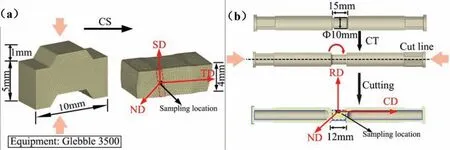
Fig.1.The methods of (a) the CS;(b) the CT processing.
The equivalent strain of CS includes the shear strain in the conventional shear stage and the compressive strain in the compression stage.CS is mainly based on two important assumptions: (1) the plane stress state is taken into account;(2) the displacement in the ND direction remains almost unchanged [29].Based on this,the stress state in the shear zone can be regarded as being approximately in the plane shear state (Fig.2a).In CS process,α,h0,andh1are set as 45°,4 mm and 5 mm,respectively,and the equivalent strains reaches 0.8.In CT process,l0,l1,R0,andθare set as 15 mm,12 mm,5 mm,and 4.1 rad,respectively,and the equivalent strains also reaches 0.8(Fig.2b).Fig.3 shows the experimental apparatus for the CS and CT process on the Gleeble-3500 thermal simulation tester.Heat the mold and samples to the 713 K (±5 K) by resistance heating,and the temperature of the samples is detected through the thermocouple wire fixed at the bottom of the initial sample.Unlike the CS process,CT requires an additional rotation unit to apply torsional stress.The equivalent strain rates of both are set to 0.001,0.01,0.1 and 0.5 s-1.After CS and CT process,air quenching nozzle is used to cold down the samples immediately,and oil-based graphite as lubricant.
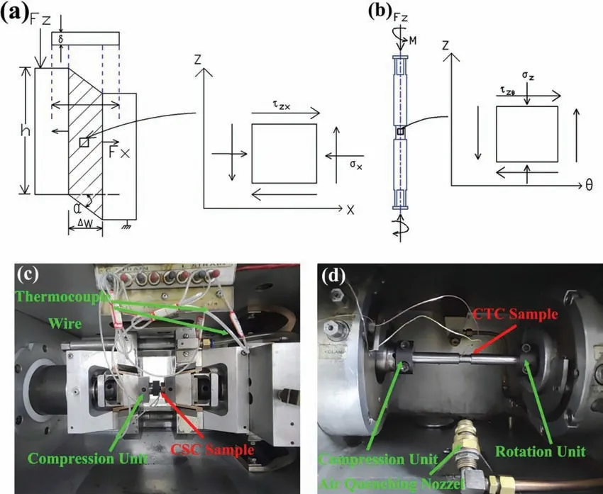
Fig.2.The stress state of the deformation zone (a) CS;(b) CT samples;the experimental apparatus of (c) CS;(d) CT samples installed in the Glebble 3500 tester.
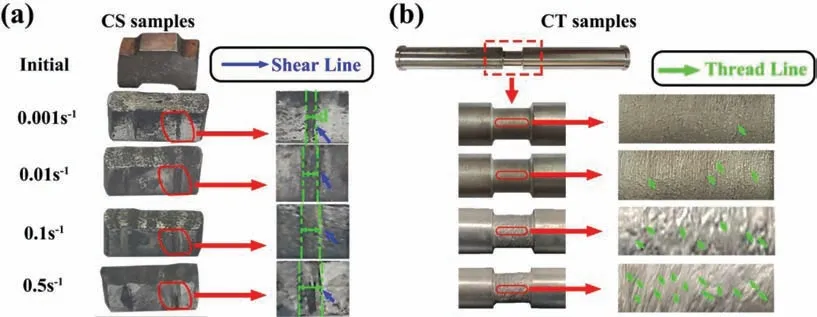
Fig.3.CS and CT samples before and after deformation.
2.3.Microstructure characterization
The optical microscopy (OM) and scanning electron microscopy (SEM) samples were prepared on a Zeiss Axio Imager-A2m microscope and a Hitachi-SU5000 SEM,respectively.Before observation,the samples need to be grounded on 2000,5000,7000 grit SiC sandpaper,and mechanically polished with 1.0 μm diamond paste,then corroded in a solution of 1 g picric acid,2 mL distilled water,2 mL glacial acetic acid and 14 mL absolute ethanol.The electron backscatter diffraction (EBSD) observations were performed on a Hitachi-SU5000 SEM equipped with an EDAXTSL EBSD system with a working voltage of 20KV and a working distance of 15 mm.Before EBSD analysis,the samples were electrochemically polished in a solution of 1 mL of perchloric acid and 9 mL of alcohol,with the working voltage of 15 V,the polishing temperature of -20~-50 °C,and the time of 105 s.Talos F200s field emission high resolution transmission electron microscopy was used to observe fine precipitates and analyze the dislocation configuration,and selected area diffraction (SAED) was used to determine the direction of the band axis.Thin foli samples for transmission electron microscopy (TEM) were prepared by punching 3 mm-diameter discs which were processed by dimple grinding and Ar+ion thinning in a precision ion polishing system(Leica EM RES101).Phases analysis was performed on a SmartLab-SE X-ray diffractometer (XRD),and the hardness properties of samples were evaluated using Vickers microhardness tester with the load of 50 g.
2.4.Finite element (FEM) simulation
Deform-3D Ver 11.0 software was used for analyzing flow behavior during the CS and CT processes.By dealing with the post-processing results in the FEM analysis,the equivalent strain distributions during the CS and CT processes could be obtained.A 3D rigid-plastic FEM model was developed to simulate the thermoforming processes.Local meshing was applied to the severely plastically deformed regions of the CS and CT samples.The FEM simulation was performed at 440 °C,and the pressing speed of the punch was determined according to the strain rate of 0.01 s-1.The punch and die were set as rigid bodies,and the samples were set as plastic bodies.The relevant mechanical parameters could refer to the previous compression experiments.The coulomb-type friction between the die and sample was set as 0.3.
3.Result
3.1.Macroscopic deformation behavior
Fig.3a shows the CS samples after deformation,which have obvious shear lines on the sides.dis defined as the width of shear lines.With the increase of the strain rate,dis obviously increased.This means that the more violent deformation is carried out.Fig.3b shows the deformation area of the CT samples after deformation,which have thread lines with pits in the middle.When the strain rate is low,the samples surface is relatively smooth,and thread lines rarely appear.The number of thread lines with pits increases significantly with high strain rate,which means that the severity of the deformation is enhanced.
The simulation results of the CS and CT deformation area in Fig.1 are shown in Fig.4.The streamline distribution of CS and CT conforms to the flow trend of metal,which proves the reliability of the simulation.Combined with the sampling positions in Fig.1,the equivalent strains of the CS and CT sample are both 0.8,which verifies the validity of the experimental design.After the CS samples are dynamically loaded,shear localization occurs due to the dual effect of shear stress and compressive stress,and shear band is formed.The equivalent strain distribution in the CS region is similar to the previous numerical simulation of the shear punch test.The strain localization occurs near the shear band,which exhibits the characteristics of localized flow [30,31].In addition,deformation region of the CS sample is wider compared with CT sample,which also reflects the advantages of CS process.Similar phenomenon is also observed in AA7075 aluminum alloy [32].Furthermore,the evolution of effective strain and stress triaxiality of the selected sampling positions is shown in Fig.4c,d.As can be seen,almost same strain (ε=0.8) is obtained for CS and CT samples with strain rate of 0.1 s-1.The minimum stress triaxiality of CS sample is -16.8,which is obvious lower than CT sample.The stress triaxiality is a parameter for evaluating the stress state,which is defined as the ratio between hydrostatic pressure (σkk) and equivalent stress(),also calledσtri=σkk/[33].The higher negativeσtrivalues in CT sample indicate that larger equivalent stress of 119.76 MPa is introduced,which is higher than 87.96 MPa in CS sample.
The shear stress and shear strain of CS sample in the conventional shear stage are
Among them,τzxis the shear stress,FZis the compressive load,Ais the shear area of the shear zone,δis the thickness of the sample,his the height of the design shear zone,γzxis the shear strain,αis the inclination,as shown in Fig.2a,Δw is the width of the shear deformation zone,andΔDis the displacement of the top die.
The equivalent stress and strain in this stage are as follows
The equivalent stress and strain in the compression process are as follows
Among them,aandbare the length and width of the compression face,h0andh1are the height before and after compression.
The stress state of CT is shown in Fig.2b.The shear stress during torsion is as follows,relevant parameter explanations could also be seen in the previous work [13].
The equivalent stress and equivalent strain are as follows
Among them
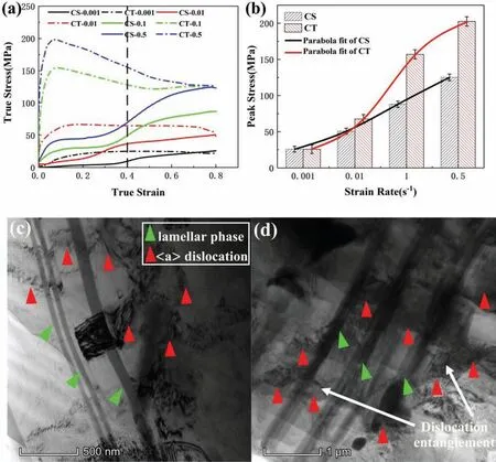
Fig.5.(a) True stress-strain curves;(b) peak stress of the alloy under different strain rate;(c) dislocations with strain of 0.15: (c) CS;(d) CT sample with strain rate of 0.1 s-1.
The peak stress increases with the increase of the strain rate in both CS and CT samples,as shown in Fig.5b,which indicates that the material has a positive strain rate sensitivity index [34].The peak stress of the CS sample at each strain rate is lower than that of the CT sample,and the difference of peak stress between CS and CT samples increases with increasing strain rate.This results are consistent with the simulation results in Fig.4d with only a maximum deviation less than 5 MPa at 0.1 s-1.For CT samples,when the strain rate is increased,the dislocations generated per unit time can increase and strain hardening can increase.However,there are not sufficient time for the grains to nucleate,and DRX process for softening need a certain incubation period,so the flow stress can increase.
Fig.6 shows the work-hardening rate curve lnθ-ε,which reflects the sensitivity of the material to work-hardening under different strain rate.The work-hardening rate lnθis positive throughout the CS curve,indicating that work-hardening dominates.The work-hardening rate curve lnθ-εof CT curve only shows a positive value in the initial stage,indicating that work-hardening is dominant only in this stage.Combined with the curve in Fig.5a,it can be concluded that the work hardening and softening compete with each other during the subsequent stage.In general,CS is dominated by work-hardening,while CT is a balance between work hardening and softening.
3.2.Microstructure and texture of the initial alloy
In Fig.7a,the microstructure of the initial sample mainly includes the magnesium matrix and black regions distributed in the grain boundaries.The black regions could not be indexed due to a low confidence factor (CI<0.1),which had been demonstrated as long-period stacking ordered (LPSO) phases and eutectic phases [35].Fig.7d shows that the phases mainly consisted of three types,namely gray bulk phase,white particle phase,and lamellar phases.The results of energy dispersive spectroscope (EDS) analysis (Fig.7e and f) shows that the chemical composition of the gray bulk phase (point A) is Mg84.96Gd5.69Y2.22Zn7.13(atomic percentage,at%),which indicates that the stoichiometry of this phase is close to Mg12(Gd,Y)Zn,also called the bulk LPSO phase.The white particle phase(point B) is Mg77.02Gd12.09Y8.15Zn2.46Zr0.29,which is close to Mg5(Gd,Y,Zn),also calledβphase.In Fig.8d,broken lamellar phases are also observed,and previous studies has shown that the lamellar phases are lamellar LPSO phases[36].Fig.7g shows the XRD pattern of the initial and deformed alloy,and the composition of initial and deformed alloy do not change,includingα-Mg,Mg5(Gd,Y,Zn) and Mg12(Gd,Y)Zn.

Fig.7.EBSD results of initial sample (a) orientation imaging microscopy (OIM);(b) optical micrograph of the sample,and the statistical distribution map of grain size was inserted;(c) (0001) pole figure (PF);(d) backscattered electron (BSE) image;(e,f) EDS results of points A and B in Fig.7d;(g) XRD pattern of the initial and deformed sample.

Fig.8.The main forms of precipitation phases and corresponding analysis of these phases.
In order to further determine the composition of the second phases,we also conductes TEM tests and analyse the experimental results.Fig.8 displays the bright-field (BF-TEM)images of CS and CT samples.According to the corresponding SAED patterns (Fig.8b),and the point EDS spectrum(Fig.8c),the lamellar phase is identified as LPSO,and the atomic arrangement of the LPSO phase is 14H.The 14HLPSO phases are also observed in Mg-Y-Zn alloy,with an ordered hexagonal structure (a=1.112 nm,b=1.926 nm,c=4.689 nm,β=83.25°) [1].Fig.9b–d shows the result of the fine particle,which has very big size with the width over 500 nm.The corresponding SAED patterns illustrates that this phase is an Mg5Gd phase.The rhombic Mg5RE phase could coexist withβ′phase in peak-aged Mg-11.1Gd-3.8Y-2.3Zn-0.6Zr alloy [37].Fig.9g and 9j show two special nano-precipitate phases,square phase and elliptical phase.In Fig.9g–i,the composition of the square phase with 50 nm in width is Mg94.64Gd2.95Y1.58Zn0.73Zr0.11,which is enriched with Gd and Y atoms.Similar phases could be observed in Mg-6.0Gd-3.5Y-0.5Zr,which possesses a face-centered cubic(fcc) structure,with an interplannar spacing equal to that of Mg5Gd phase (a=2.23 nm) [38].In Fig.9j–l,the composition of the elliptical phase with 50 nm in diameter is Mg80.22Gd1.09Y0.7Zn7.06Zr10.92,which is enriched with Zn and Zr atoms.These small precipitates play the role of pinning dislocations to a certain extent,limiting the growth of grains or the coarsening of microstructures [39].

Fig.9.Optical micrographs of the samples with the true strain of 0.8 at different strain rates: (a,b) 0.001 s-1;(c,d) 0.01 s-1;(e,f) 0.1 s-1;(g,h) 0.5 s-1;(a,c,e,g) CS;(b,d,f,h) CT samples.
3.3.Microstructure evolution
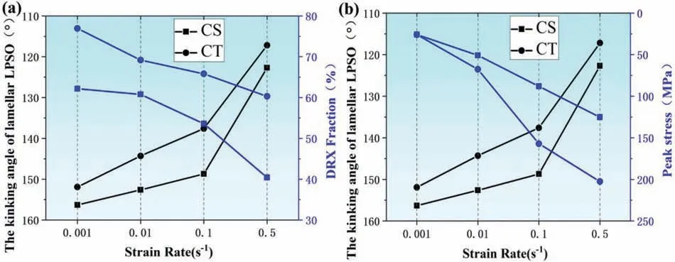
The lamellar LPSO phases are appeared as strengthening phases to understand plastic deformation,and the kink bands are formed by the generation of dislocation pairs of opposite signs on the basal plane and synchronous slip to adapt to the strain [40].The lamellar LPSO can achieve uniform intragranular strain by forming kink bands.At the same time,the uniformity of the microstructure is increased,and the (0001)basal texture is weakened [41].Taking CS as an example,as the strain rate increased,the degree of kinking of the LPSO phases also increase.When the strain rate was 0.5 s-1,a large amount of lamellar LPSO phases are kinked until broken,and the kink angle is about 122.7°.When the strain rate reached 0.1 s-1,the kinking degree of the lamellar LPSO is still large,and the kinking angle reaches about 148.7°,while the kinking of the lamellar LPSO is smaller.When the strain rate was 0.01 s-1and 0.001 s-1,the lamellar LPSO is also less kinked,with kink angles of about 152.6° and 156.3°,as shown in Fig.9.The lamellar LPSO phases of CT sample show the same kinking trend as CS sample,and the kinking degree of lamellar LPSO is: CT>CS.When the basal slip is hindered,the kinking of the lamellar LPSO phase becomes the dominant deformation mode,which can improve the alloy plasticity to a certain extent.When the strain rate is high,high peak stress (Fig.5b) requires the lamellar LPSO phase play a key role in the work hardening process.
Fig.10 shows EBSD results of CS and CT samples with the true strain of 0.8 at different strain rates.The magnesium matrix includes a small amount of large deformed grains and a large number of fine grains,namely DRX grains,showing the characteristics of a bimodal structure.The statistical distribution map of grain size could be seen in Fig.10e,f and m–p.Relative to the initial sample with an average grain size of 16.60 μm (Fig.7c),there is a significant decrease of grain size after CS and CT processes.Besides,the average grain size of CS and CT samples shows a decreasing trend with the increase of strain rate.Yu et al.studied the DRX behavior of Mg-12Gd-4.5Y-2Zn-0.4Zr during hot compression and found that the average grain size of the alloy decreased with the increase of strain rate,which was caused by a significant increase of LAGBs.In addition,the average grain size of the CS is higher than that of the CT sample.This also shows that the grain refinement effect of CT is stronger than that of CS.

Fig.10.EBSD IPF maps of the samples: (a~d) CS;(i~l) CT samples;the corresponding statistical distribution map of grain size: (e~h) CS;(m~p) CT samples.
In Fig.11,the grains with grain orientation spread (GOS)less than 2 could be recognized as DRX grains,and the DRX area fraction was represented bypDRX.The degree of recrystallization of CS and CT samples basically shows a decreasing trend with the increase of strain rate.This is probably because when the strain rate is low,there is sufficient time for DRX to proceed,so the degree of recrystallization is high.In addition,under the same strain rate,the main trend of DRX fraction is: CT>CS.The misorientation angle distribution diagrams for CS and CT samples (Fig.11e,f and m–p) also shows the same trend.It could be seen that the fraction of LAGBs of the CS samples increases from 21.3% to 43.3% with increased strain rate,which is because that the DRX fraction is decreased and the number of large deformed grains with high fraction of LAGBs increases at larger strain rates.In comparison,the CT samples have a lower fraction of LAGBs than the CS samples,mainly because the DRX of the CT samples is more fully performed.

Fig.11.EBSD IPF maps of the DRX region: (a~d) CS;(i~l) CT samples;the corresponding misorientation angle distribution diagrams: (e~h) CS;(m~p)CT samples.
Besides,the grain size of the DRX grains shows a decreasing trend with the increase of strain rate,as shown in Fig.11e–h,m–p.The relationship between DRX grain size and deformation parameters follows the Zener-Hollomon criterion [42]:
Among them,,A,˙εis the DRX grain,a constant,and the strain rate,respectively,Qis the activation energy(KJ/mol),indicating the difficulty of plastic deformation,Tis the absolute temperature,andRis the gas constant.According to the above formula,the strain rate can significantly affect the DRX grain size,and grain refinement of DRX grains can be effectively promoted with the increase of strain rate.
3.4.Texture development
Fig.12a-h shows the (0001) inverse pole figures of the CS and CT samples.When the increase of strain rate,much more concentrated texture and higher (0001) intensity of CS are obtained,which means the stronger basal texture.CT sample shows similar trend,and the texture intensity basically reflects the trend: CS>CT.Besides,(0001) basal texture intensity of CS and CT samples is lower than the initial sample with a maximum pole density of 6.047 (Fig.7).

Fig.12.EBSD-based pole figures: (a~d) CS;(i~l) CT samples;the corresponding inverse pole figures: (e~h) CS;(m~p) CT samples.
In order to further interpret the texture evolution,the corresponding pole figures are also analyzed.For the CS samples (Fig.12e–h),when the strain rates reached 0.001 s-1and 0.01 s-1,it contains three texture components,namely strong texture (0001),weak texture distributed between(22)and(21),and(101)weak texture.(0001) plane can be seen as a typical basal fiber texture,most of which is parallel to the ND direction.When the strain rate is increased to 0.1 s-1,it converts to a dual texture component,as(101)weak texture disappears.When the strain rate increased to 0.5 s-1,it transforms into(100)strong texture and(101)weak texture,indicating that non-basal slip is activated as the main slip mode.For the CT sample,when the strain rate is 0.001 s-1,it contains dual texture components,a strong texture distributed between(100)and(20),and(24)weak texture.(24)has been demonstrated as a RE texture,which leads to the formation of the high Schmid factor for basal slip.When the strain rate is increased to 0.01 s-1,it converts to a single texture component,which is(102)strong texture.When the strain rate reached 0.1 s-1and 0.5 s-1,it converts to(20)strong texture,indicating that the non-basal slip is dominant in the CT process.Among them,(20)was also observed in the extruded RE-free Mg alloys after a full DRX process[43].It can be concluded that the(100)of CS samples and(20)texture of CT samples are observed when the strain rate reaches 0.5 s-1,indicating that a large number of DRX grains appears.In conclusion,for the same strain rate,CT has more texture components and more dispersed texture distribution than CS sample,so the texture strength of CT is weaker than that of the CS sample.With the increase of strain rate,CS sample evolves from 3-texture components to dual-texture components,while CT sample evolves from dual-texture components to single-texture components.
4.Discussion
4.1 The effect of strain rate on DRX behavior
In Fig.13a,when the strain rate is increased,the DRX fraction and the grain size of CS sample is decreased,which is different from the previous result that DRX fraction can bring higher grain refinement [44].This was related with the bimodal microstructure after CS deformation.When the strain rate is high,there is less time to convert the deformation storage energy into the driving force for grain boundary migration,so the DRX fraction is decreased.However,when the strain rate is high,the presence of a large number ofβphases(Fig.18) will play a nailing effect on the growth of grains,so the actual average grain size is decreased.The influence of strain rate on grain refinement requires consideration of DRX behavior and the second phase.In Fig.13b,with the increase of grain size,the texture strength of CS sample is enhanced.This is because the texture strength was also contributed by the coarse grains [13],and large coarse grains become more and texture strength is enhanced.Similar regularity can be observed on CT sample.For the certain strain rate,the CT sample has smaller average grain size,higher DRX fraction,and lower texture strength compared with the CS sample.
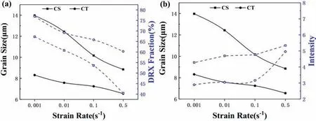
Fig.13.(a) The comparison of average grain size and DRX fraction of CS and CT sample;(b) the comparison of average grain size and intensity of CS and CT sample.
In Fig.14a–d,when the loading direction is parallel to the basal,prismatic,or pyramidal plane,the Schmid factors of CS samples are very high.These slip systems are easily activated,so basal,prismatic,and pyramidal slip are the dominant deformation mechanisms.Due to the addition of RE elements,the ratio of the close-packed hexagonal axes is reduced,and the pyramidal slip is enhanced [1].This is different from the traditional compression method that only basal slip is activated [45].CT samples show the same trend,as shown in Fig.14i–l.As simple shear modes,CS and CT are helpful for the driving of the non-basal slip systems,especially pyramidal slip is greatly activated.
With the increase of the driving force of the non-basal slip,the texture can deflect to some extent,as shown in Fig.14e–h,m-p.For the CS sample with a strain rate of 0.01 s-1,the maximum intensity point of the polar axis of the basal plane is expanded to TD by about 45°.For the CT sample with a strain rate of 0.01 s-1,the maximum intensity point of the polar axis is inclined to ED by about 20°.The rotation of(0001) plane makes the texture distribution more random,and with the increase of the cumulative strain,a high density of dislocations can be induced [46].This also gives sub-grains enough driving force to form,and then a large number of DRX grains are formed [43].CS and CT show the commonalities of simple shear,namely the non-basal slip is easily activated and the texture is deflected greatly.The detailed DRX behaviors of CS samples can be introduced next.
In order to further analyze the DRX behaviors differences between CS and CT,Fig.15 shows the work-hardening rate curve -(∂(lnθ)/∂ε)-ε,which can indicate the occurrence of DRX critical strain [47].The initiation of DRX is associated with the inflection point on the curve of the strainhardening rate lnθ-ε,corresponding to the minimum point in the -(∂(lnθ)/∂ε)-εcurve.For example,the critical strain of CS sample is 0.21 when the strain rate reaches 0.01 s-1,while CT sample is 0.06.In general,the DRX critical strain of the CS sample is between 0.20 and 0.32,while that of the CT sample is between 0.035 and 0.16.This indicates that the DRX of the CT sample is easier to be activated.

Fig.15.Work-hardening rate curve -(∂(ln θ)/∂ε)-ε for (a) CS,(b) CT.
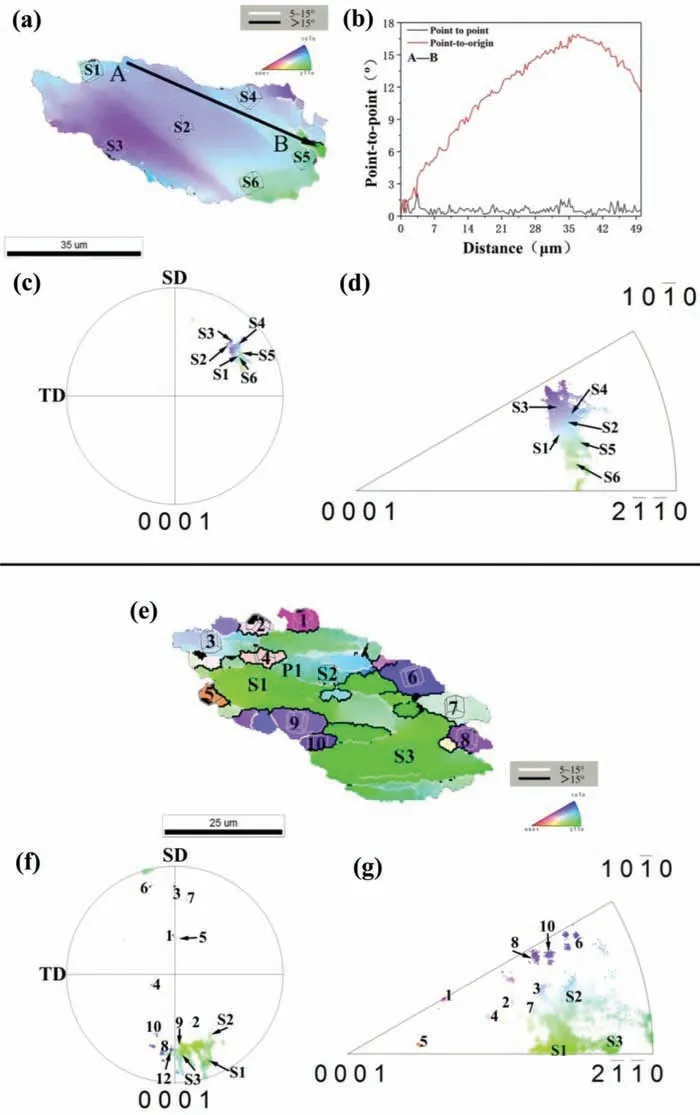
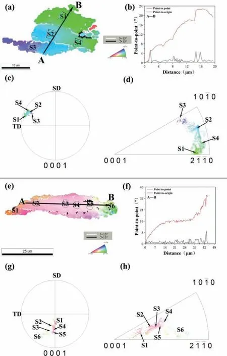
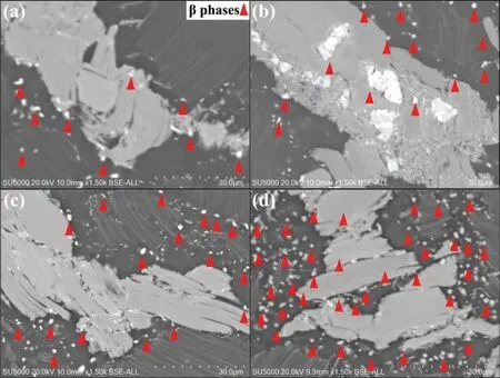
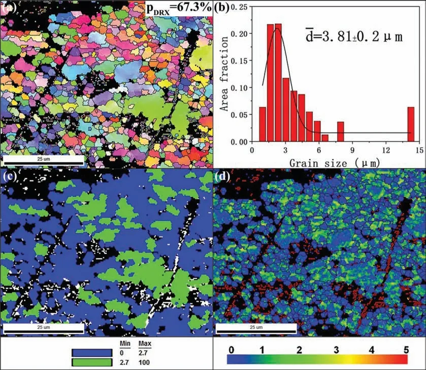
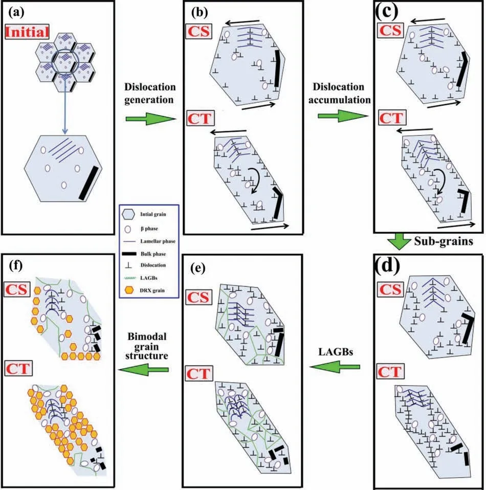
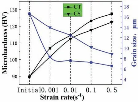
Fig.16 shows the KAM diagram of CS and CT samples.The Kernel average misorientation (KAM) diagram can illustrate the distribution of the dislocation density,and higher KAM value often means higher dislocation density.The mean misorientation angle of the CS sample gradually increases with the increase of strain rate,which indicates a higher dislocation density induced by the more inadequate DRX process.In general,the relationship among the average KAM values for a certain strain rate is: CT Fig.16.KAM diagram: (a~d) CS;(i~l) CT samples;the corresponding distributions of the Kernel average misorientation: (e~h) CS;(m~p) CT samples. In order to more intuitively show the evolution trend of dislocations at grain boundaries,the bright-filed images of the dislocations structures are shown in Fig.17.The micrographs show the same area under different conditions (see insets for the diffraction vector g).Dislocations are visible both under g=0002 and g=110 as indicated by the red arrows.According to theg·bcriterion(where b was the Burgers vector),dislocations with different Burgers vectors were visible wheng·b/=0,and the dislocations could be judged as Fig.17.The bright-filed images of dislocations with strain rate of 0.5 s-1 (see the inlet for diffraction vector g): (a) and (b) were images of the same position under different conditions from the CS sample;(c) and (d) were images from the CT sample.Corresponding SAED patterns were inserted. In order to understand the DRX behavior,typical grain of CS sample with strain rate 0.001 s-1is extracted from the frame area in Fig.10a,as shown in Fig.18a.Fig.18b shows the change curve of the misorientation.The misorientation along the line AB increases continuously,especially when passing through the high angle grain boundaries (HAGBs),indicated by a white line,indicating that the dislocation in this region has a higher mobility.The moving dislocations are continuously captured and absorbed by the LAGBs,and the final rotation of the grains makes the LAGBs transform into HAGBs and forms new DRX grains.This phenomenon is known as CDRX [49].In addition,bow-out nucleation of grains can also be observed,which is also a feature of DDRX,as shown in Fig.18e.In addition,the similar orientation of the sub-grains can be seen in Fig.18c and d,while different orientations of DRXed grains can be seen in Fig.18f and g,which means more random texture distribution.CDRX and DDRX have synergistic effect,and CDRX dominates in the process.The same CDRX can be observed when the strain rate reaches 0.01 s-1,as shown in Fig.19a–d.At the same time,some fine grains can also be observed at the trident,as shown in Fig.19e.The color is different from the color of the nearby grains,and it can be judged as newly generated DRX grains.This is also the characteristic of DDRX.It can be concluded that DRX grains can be further refined by DDRX on the basis of CDRX grains. Fig.18.The DRX behavior: (a) an enlarged diagram of the block area in Fig.10a (S: subgrain);(b) misorientation of point to origin along AB in (a);the corresponding grain orientations highlighted in (c,f) (0001) pole figure and (d,g) inverse pole figure;(e) an enlarged diagram of the elliptical area in Fig.10a(P: deformed parent grain; i=1,2 …: DRXed grain). When the strain rate reaches 0.1 s-1and 0.5 s-1,the characteristics of CDRX can be observed,as shown in Fig.20a–h.The formation of LAGBs is related to the rapid climbing of dislocations,which are transformed into HAGBs by continuously absorbing moving dislocations,forming a threedimensional dislocation network at sub-grain boundaries [49].At this time,DDRX is more difficult to be observed,which also indicates that DDRX has not enough time to proceed with high strain rate,and CDRX plays a leading role in the process.When the strain rate is high,the texture becomes more concentrated,as shown in Fig.12,which makes the non-basal slip more difficult to be activated,so dislocations are difficult to move,and DDRX is more difficult to be proceeded. Fig.20.The DRX behavior: (a,e) an enlarged diagram of the block area in Fig.10c.d;(b,f) misorientation of point to origin along AB in (a,e);the corresponding grain orientations highlighted in (c,g) (0001) pole figure and (d,h) inverse pole figure. In addition,DRX behavior can be also observed near the LPSO phases.When the dynamically precipitated particles are larger than 1 μm,they can be used as the sites for DRX grains nucleation,that is,the so-called particle stimulated nucleation (PSN) [36].In Fig.21,the DRX grains on both sides of the bulk LPSO phases can be observed.This was a kind of PSN behavior [50].In conclude,the bulk LPSO phase can promote DRX behavior through the PSN mechanism at the initial stage.At the subsequent stage,when LPSO phases are broken into smaller parts,even particles,grain growth can be limited through pinning effect.A similar behavior can be observed in the DRX behavior of Mg-9Gd-4Ye2Zn-0.5Zr during repetitive upsetting-extrusion (RUE) process,and the inhibition effect and promotion effect of LPSO phases can be transformed into each other. The effect of strain rate onβphases of CS samples is discussed,as shown in Fig.22.A large amount ofβphases are present at the grain boundary,and increase in number with the increasing strain rate.After recrystallization,grain growth occurs due to the driving force of reduced total interfacial energy [51].The second phase can hinder the movement of dislocations by pinning dislocations,and limit migration of grain boundaries,thus the grain grow can be inhibited.When the strain rate is increased,the inhibition of grain growth can enhance,and the smaller grain size can be obtained,as shown in Fig.22.CT samples show a similar deformation characteristic to CS samples,and the pinning effect ofβphase plays a vital role in final average grain size. Fig.22.SEM images of the β phases precipitation behavior of CS samples under different strain rate: (a) 0.001 s-1;(b) 0.01 s-1;(v) 0.1 s-1;(g-h) 0.5 s-1. In addition,the solid solubility of Gd is 14% (mass fraction)at 723 K and 21%at 803 K[10].From the point of view of thermodynamics,Mg5(Gd,Y,Zn) particles have a strong tendency to solid solution in a high temperature environment.When the strain rate increases,a significant temperature rise is caused,which increases the solid solubility of the particles,but the opposite phenomenon occurs in Fig.22.This is probably that high density of dislocations and vacancies are formed when the strain rate is increased,which provides a high diffusion path for RE elements,so that the precipitation of particles is enhanced instead. The DRX behavior of samples is related to the kinking of LPSO phases,especially the lamellar LPSO phases.In Fig.23,with the increasing strain rate,the kinking angle of lamellar LPSO is decreased,which indicates that the kinking of the lamellar LPSO is enhanced.At the same time,the DRX fraction is decreased.This is because that lamellar phases and grains are synergistic in accommodating plastic deformation,and when the lamellar LPSO shares more strain by kinking behavior,the distortion energy of the grains is correspondingly weakened,and the driving force to reach DRX is more difficult to be satisfied.Besides,since the lamellar LPSO phases can hinder the basal dislocations movement effectively,and basal dislocations piles along the lamellar LPSO phases,which causes the stress concentration between Mg matrix and LPSO phases [41],so the samples with high strain rate display higher peak stress (Fig.23b). Fig.23.(a) The kinking angle of lamellar LPSO and DRX fraction of deformed alloys;(b) the kinking angle of lamellar LPSO and peak stress. When the LPSO phase kinking band and the DRX process can not adapt to the deformation with high strain rate,adiabatic shear bands (ASBs) are found,which indicates crack initiation and may lead to failure of the sample.In other words,the existence of ASBs is a supplementary mechanism for the LPSO phase kinking and DRX process.The formation of adiabatic shear bands can cause a large grain refinement.This is due to the stress concentration caused by the local flow,and a large amount of DRX occurs,and this is also the source of cracks and eventual failure [52].As shown in Fig.14d,when the strain rate reaches 0.5 s-1,the prismatic slip of CS sample is reduced,which shows that the slip of the non-basal plane is limited to a certain extent.When the strain rate reaches 0.5 s-1,the DRX fraction is only 40.3%,as shown in Fig.13a.The DRX fraction of CS sample is low,indicating that deformation energy storage produced by the plastic deformation can not be consumed by dislocations.Besides,the kinking degree of LPSO phases is small (Fig.23),so there are other plastic deformation mechanisms responsible for the high peak stress(Fig.5b). All grains in the initial microstructure are free of ASBs,which means that ASBs observed in Fig.24 are formed during dynamic loading rather than EDM cutting,mechanical polishing or casting process.In Fig.24a,the existence of crack can be observed,and its boundary is relatively clear.It shows that there is a large shear deformation in this region.ASBs are formed along the direction of 45° to shear direction (SD),which indicates that under the CS process,an obvious deformation localization phenomenon occurs,and the direction is consistent with the maximum shear direction[53].Local flow instabilities induced by shear tends to occur at high strain rates [54].Yang found through hot compression experiments on Mg-9Gd-2.9Y-1.9Zn-0.4Zr-0.2Ca alloys that micro-cracks tended to be located at the intersection of high-angle kink bands and the interface between LPSO phase and Mg matrix.This is due to the inability of DRX to relieve stress concentration,the bulk LPSO phase with high-angle kinking bands at grain boundaries,especially triple junctions prone to stress concentration,becomes the source of cracks[55]. Fig.24.The detailed maps of adiabatic shear band of CS sample under strain rate 0.5 s-1: (a) the enlarged inverse pole figure of the red frame in Fig.10d;(b) the statistical distribution map of grain size;(c) grain orientation spread (GOS) map;(d) KAM map. In Fig.24b,the grains in ASBs are refined to a certain extent.It can be seen that the activation of DRX at high strain rates can be partly due to the increase in the adiabatic temperature in the shear band,which gives the grains sufficient activation energy to form a fine DRX structure.Zhou found further deformations caused the further splitting of dislocations,and DRX grain was formed [53]. Fig.24c shows the grain orientation spread.The DRX fraction of grains in the ASBs region reaches 67.30%,which was much higher than 50.43% in the whole region (Fig.13a),which indicates that the existence of ASBs greatly promotes the process of DRX.Fig.24d shows the Kernel average misorientation (KAM) map.The KAM value can reflect the stored energy of the measured point.The blue area representes the low energy region,while the green area representes the high energy region.In other words,the energy of the grains in ASBs is much lower than that of the grains in Fig.10d.Therefore,a large number of dislocations existe in the whole region after loading,while less dislocations in ASBs. CT is the combination of simple torsion and compression,while CS is the combination of conventional shear and compression,and simple torsion and conventional shear are two basic simple shear modes,as shown in Fig.25a–d.For a given strain rate,the pathes of CS and CT are different.The CT sample is sheared with torsion,and the path of CT sample is longer compared with CS sample,as shown in Fig.25e.The metal flow track of the CS sample is relatively simple,and the six track points only move along the shearing direction,while the metal flow track of the CT sample is complicated and the six track points of the CT sample not only flow along the shear direction,but also a certain circular motion along the circumference,as shown in Fig.25f. Fig.25.Force Analysis of the in-plane for (a) CS and (c) CT samples;deformation of a line for (b) CS and (d) CT samples;(e) shearing path for CS and CT samples;(f) metal flow track lines for CS and CT. Since CDRX can be observed at all strain rates in the current study,while DDRX only appears at certain strain rate,as shown in Figs.18–20.So only the influence mechanism of the development of CDRX can be schematically discussed next.The initial near-equiaxed grains(Fig.26a)are elongated along the shear direction when subjected to complex shear stress.At the same time,due to the elastic modulus difference between theβprecipitates and magnesium matrix,dislocations are generated near the grain boundaries and second phases to accommodate plastic deformation (Fig.26b).During the dislocation accumulation process,the second phases can pin dislocations and the dislocations movement would be hindered(Fig.26c).As the deformation degree further increased,the dislocations are rearranged and gradually form sub-grains,as shown in Fig.26d.The progressive rotation of the lattice occurs due to local shearing at the grain boundaries [56],so sub-grain boundaries tend to be generated near the original grain boundaries.With further deformation,the sub-grain boundaries can absorb a large number of dislocations,thereby increasing its misorientation and developing into zigzag lowangle grain boundaries (LAGBs),which increases the critical storage energy of DRX,as shown in Fig.26e.Finally,the LAGBs continuously absorbs dislocations,coupled with the rotation of the lattice,which are developed into a necklace structure with fine DRX grains along the grain boundary,and a bimodal grain structure composed of DRX grains and deformed grains is formed eventually,as shown in Fig.27f. Fig.26.Schematic illustration of grain refinement difference during CS and CT processes. In this process,compared with CS sample,the stress triaxiality of the CT sample is larger (Fig.4b),so the plastic deformation degree of grain is also larger.At the same time,the peak stress of CT samples is higher than CS sample (Fig.5b),so the grain elongation of CT sample is larger.The CT sample is subjected to higher local shear stress,the dislocations density of the CT sample at various positions can be larger.Dislocations of CT sample are more seriously piled up,which are also rotated when they move,so the distribution path is longer,as shown in Fig.26c.This dislocation movement path can be called“rotational dislocation accumulation”,which can coordinate the strain to a certain extent.Therefore,due to more serious dislocation pile-up and the longer distribution path of the CT sample,more sub-grains and LAGBs are formed.Compared with the CS sample,more HAGBs of CT sample are formed,and more DRX grains are formed from grain boundary to grain interior.So the area fraction of LAGB of CT sample is smaller than that of the CS sample,showing better grain refinement effect. Taking CS samples for examples,the grain refinement is greatly affected by the second phases.On the one hand,due to the difference of elastic modulus between LPSO phases andα-Mg,strong stress concentration occurs at the phase boundaries,and a large number of dislocations are accumulated[57].This can be called PSN mechanism.On the other hand,with the LPSO phase breaking and solid solution and theβphases precipitation,the grain growth could be hindered by pinning effect.At low strain rate (Fig.27),because the number of second phases are relatively small (Fig.22),the grain growth can not obviously hindered and DRX process continues.At high strain rate,it is difficulty for grains to growth due to large number of second phases within grains and at grain boundaries,so the average grain size and DRX fraction are small.In conclude,the DRX process can be promoted by the PSN mechanism of second phases,and the grain growth can be restricted by the pinning effect of second phases.Therefore,regulating the second phases is of great significance to refining grain. To investigate the mechanical property evolution of alloy,ten points are selected for each sample,and the average microhardness value is taken as the final microhardness value,as shown in Fig.28.With the increase of strain rate,the microhardness of CS and CT samples decrease to a certain extent.This is because with the decrease of strain rate,there will be more time for deformation,and the deformation energy will be reduced through recovery and recrystallization,resulting in the corresponding decrease in microhardness.In addition,the microhardness of CS sample is smaller than that of CT sample,which is mainly due to the stronger grain refinement effect of CT sample. Fig.28.Microhardness values of the Mg-Gd-Y-Zn-Zr alloy before and after CS and CT process. The yield strength of the alloy is directly related to the grain size.According to the Hall-Petch formula [4],the yield strength of the alloy is Among them,dis the average diameter of the grains,kyis the slope of the straight line,andσ0is the initial yield point strength.There is positive correlation between microhardness and yield strength [35],so the relationship between microhardness and grain size is also basically positive.In conclude,for the same strain rate,the increase of microhardness of CT samples is related to the smaller average grain size. In this paper,the following conclusions were drawn through the research on the grain refinement and texture evolution under complex shear stress conditions: CS and CT. (1) The peak stress of the CS sample at each strain rate is lower than that of the CT sample,and the difference of peak stress between CS and CT samples increases with the increase of strain rate.The stress-strain curve of CS is dominated by work-hardening,while CT is a balance between work hardening and softening. (2) When the strain rate is increased,the average grain size of CS and CT samples are decreased,and the grain size of DRX grains is also decreased.This is probably because that the precipitation number ofβphases is more while the strain rate is increased,and the hindering effect on grain growth can be significantly enhanced.The dynamic recrystallization (DRX) fraction of CS and CT samples are decreased with the increase of strain rate.The low DRX fraction is related to the insufficient time for the grains to nucleate.The DRX process can be promoted by the PSN mechanism of second phases,and the grain growth can be restricted by the pinning effect of second phases.At the same time,the texture strength is enhanced with the increase of strain rate,which is also associated with increased undeformed grains.Besides,the kinking of lamellar LPSO is increased when the strain rate is increased. (3) Under complex shear stress conditions,non-basal slip,especially pyramidal slip,is easily activated and the texture is deflected greatly.This is different from the traditional compression method that only basal slip is activated. (4) Adiabatic shear bands (ASBs) are formed along the direction of 45°to shear direction(SD)in CS sample with strain rate of 0.5 s-1.ASBs act as the supplementary plastic deformation method,and the grains in the ASBs are greatly refined. (5) Compared with the CS samples,CT samples have smaller average grain size,higher DRX fraction,and lower texture strength for a certain strain rate.This is because that the CT samples are sheared with torsion,the dislocation movement path can be called “rotational dislocation accumulation”,and the paths of Acknowledgments This work was financially supported by Project supported by the Joint Funds of the National Natural Science Foundation of China (Grant No.U20A20230),Natural Science Foundation of Shanxi Province (No.201901D111176),Project supported by the Key R&D program of Shanxi Province (No.2020XXX015),Research Project Supported by Shanxi Scholarship Council of China (2021-127),Graduate Education Innovation Program of Shanxi Province (2022Y579). Data availability The raw/processed data required to reproduce these findings cannot be shared at this time as the data also forms part of an ongoing study.

4.2.The effect of strain rate on second phases
4.3.The formation of adiabatic shear bands
4.4.The grain refinement mechanism under complex shear stresses

4.5.The effect of strain rate on mechanical property
5.Conclusion
 Journal of Magnesium and Alloys2023年7期
- Journal of Magnesium and Alloys的其它文章
- Recent progress in MgB2 superconducting joint technology
- “Smart” micro/nano container-based self-healing coatings on magnesium alloys: A review
- Recent advances using equal-channel angular pressing to improve the properties of biodegradable Mg–Zn alloys
- Twin evolution in cast Mg-Gd-Y alloys and its dependence on aging heat treatment
- Effects of Ce content on the modification of Mg2Si phase in Mg-5Al-2Si alloy
- Solute drag-controlled grain growth in magnesium investigated by quasi in-situ orientation mapping and level-set simulations
