Unusual F3 stacking fault in magnesium
Y.Yue,S.L.Yang,C.C.Wu,J.F.Nie
Department of Materials Science and Engineering,Monash University,Victoria 3800,Australia
Abstract An unusual F3 basal stacking fault resulting from twin-dislocation interaction in magnesium is observed in molecular dynamics simulation.The F3 fault is produced in the twin lattice from the interaction between a migrating (102) twin boundary and a partial dislocation of either a prismatic
Keywords: Magnesium;Basal stacking fault;F3 fault;Twin-dislocation interactions.
1.Introduction
Stacking fault (SF) is a planar defect that occurs when the normal stacking sequence is changed.In hexagonal close packed (HCP) crystals such as magnesium (Mg),basal SFs on the (0002) close-packed planes have low energy,and thus they can form readily [1].There are generally four types of basal SFs,including intrinsic I1and I2,extrinsic E [1–4]and twin-like T2[1,4,5].Basal SFs formed in Mg are normally I1and I2faults[6–13].While the influences of the basal stacking faults on plastic deformation and mechanical properties have been studies in recent years at both experimental and computational levels,there exist controversial reports [14–16].For example,Sandlobes and co-workers [15]have proposed that the I1fault can act as a source for
For the I1faults,they are traditionally thought to form by removing a basal plane above a specific plane via vacancy condensation followed by the subsequent shearing of the remaining planes above this specific plane by[2–4],or by basal-dissociation of a
An I2fault is associated with a stacking sequence change of BABABCAC or ABABACBC.It is generated by shearing the basal planes by,or dissociation of a perfectdislocation[1–4,20–22],where thedislocation can result from the decomposition of a
For a T2fault,it has been thought to form from an I2fault[27–29].For example,a T2fault associated with a stacking sequence change of ABABCBABA can be generated from an I2fault associated with a stacking sequence change of ABABCACAC by further shearing the lattice from the plane one-basal-layer below the plane C of the I2by,as illustrated in the DFT work conducted by Han et al.[27].It may also form in association with the segregation of solute atoms,generated by displacing some atomic columns byon a single basal plane,as observed experimentally in Mg-Sn alloys [5].For an extrinsic E fault,it can be generated by inserting an extra C plane into the hexagonal stacking sequence[2,3]or by dissociation of a perfect
Apart from the above four types of basal SFs,an unusual basal stacking fault designated F3has been briefly mentioned in a previous DFT work conducted by Han et al.[27].The F3fault is supposed to be produced from the sequential faulting mechanism in the work of Han et al.[25].In such a process,an I2fault was generated first through the gliding of a 90°Shockley partial,which was followed by the formation of a T2fault from the resultant I2by the gliding of a 30° Shockley,after which the glide of another 90° Shockley from the resultant T2produces an F3fault.The F3fault can be viewed as consisting of a pair of intrinsic I1faults that are separated by two basal layers,as suggested by Han et al.[25].A pair of I1faults that are separated by a larger number of basal layers was also observed in the MD simulation conducted by Zhou et al.[25],and this pair of I1faults was generated from the interaction between a(102)twin boundary and basal-dissociated
In the present work,the F3fault is studied in depth.It is observed for the first time in Mg in MD simulations.It forms unexpectedly from the interaction between a migrating(102)twin boundary and a matrix prismatic
2.Methods
2.1.Computational procedures
MD simulations were carried out using LAMMPS [31].The modified embedded atom method (MEAM) potential developed by Wu et al.[32]was used to describe the interactions among Mg atoms.The simulation results were analyzed and displayed with Open Visualization Tool (OVITO) [33].A bi-crystal model satisfying the(102)twin relationship was constructed.The perfect prismatic
2.2.Designations of different types of dislocations and stacking faults
Disconnection on the(102)twin boundary are represented byb±p/±q[39–45],where the superscript “+” or “-”indicates the step ‘up’ or ‘down’ with respect to the matrix lattice,and the subscript “p” or “q” indicates the number of inter-planar spacing of the {102} planes corresponding to the height of the step in the matrix or twin lattice.A disconnection with riser plane parallel to a BP or PB interface[46–48],is represented by BPb-p/-qor PBb+p/+q.The notation ofb±p/±qis also used to represent the lattice dislocation[43,44].For a dislocation in the matrix or the twin lattice,the q or p always equals zero.Dislocation in the matrix that has a Burgers vector equal to a prismatic
3.Results
3.1.F3 stacking fault and its formation process
3.1.1.Formation condition of F3
whereb-2n/-2nandb2n/2nrepresent the BP disconnection that connects thefault and the PB disconnection that connects thefault,respectively.Theb2/2andb-2/-2represent the PB and BP twinning disconnections (TDs) on the twin boundary,which are not illustrated in the figures.
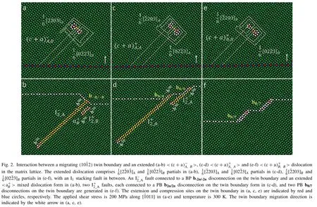
and the interaction in Fig.3c-d is described by the equation:

Fig.3.Interaction between a migrating (101) twin boundary and an extended (a,c) < B> edge dislocation in the matrix lattice.The extended dislocation comprises two <> partials,with an extrinsic stacking fault in between.The twin and <> interaction produces either an extended basal < >mixed dislocation or a F3 fault in the twin lattice.The extension and compression sites on the twin boundary in (a,c) are indicated by red and blue circles,respectively.The applied shear stress is 200 MPa along [011]in (a-d),and temperature is 300 K.The twin boundary migration direction is indicated by the white arrow in (a,c).
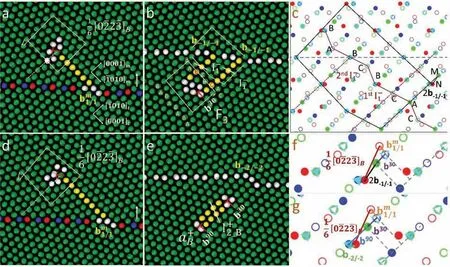
Fig.4.Interaction between a migrating (101) twin boundary and a [02]B Frank partial dislocation,produces (a-b) a F3 fault or (d-e) an extended basal <> mixed dislocation in the twin lattice.Total Burgers vector of two b-1/-1 disconnections connected with a F3 fault in (b) is given by MN in the polychromic complex in (c).In the polychromic complex,the red and dark blue lattices represent respectively the matrix and twin crystal.The light blue and green lattices represent the crystals that have same orientation as the twin crystal,but with the stacking sequence changed by I1 and faults,respectively.Atomic positions in two adjacent (20) planes are indicated by solid and open circles.The applied shear stress is 200 MPa along [011]in(a-b),and temperature is 300 K.The twin boundary migration direction is indicated by the white arrow in (a,d).Relationship among Burgers vectors of lattice dislocation and twin boundary disconnections for reactions (a-b) and (d-e) are illustrated in (f) and (g) respectively.
The products obtained from the interactions between different types of prismatic
Table 1Different types of products resulting from the interaction between a (102) twin boundary and a partial dislocation of prismatic

Table 1Different types of products resulting from the interaction between a (102) twin boundary and a partial dislocation of prismatic
3.1.2.Formation process of F3and 5 are located,and column 4 (indicated in red color) is located just above the
Due to the formation of theb30Shockley in the twin lattice,the migration of the twin boundary results in the formation and extension of the plane C between theb30and the migrating boundary.All the planes below the lying plane of theb30,and lying between theb30and the twin boundary,undergo a transition of B→A and A→C (Fig.7a).Therefore,the stacking sequence of basal planes (from the plane one-layer above,to the plane two-layer below the lying plane of theb30) is changed from BABA to BCAC,generating the firstfault.The stacking sequence change associated with the first I1fault is similar to that caused by anfault with ab30at the end (Fig.7b,c).The migration of the twin boundary is also accompanied with a transition of A→C of the atomic columns in the plane lying two-basal-layer above theb30and between the atomic column 4 and the twin boundary,Fig.7d,which is caused by the displacement of the atomic column 4.If the atomic column 4 stays at its position between the columns 3 and 5,then an<>dislocation will form after the absorbed dislocation detached from the twin boundary.This<>comprises ab90and ab30Shockley that are located at the far and the close ends towards the twin boundary,with anfault in between (Fig.7e).In this case,the position of atomic column 4 can be indicated in position C0in the trichromatic pattern in Fig.7f.However,the atomic column 4 has moved along the [000]tby one-layer to the position between the columns 6 and 7,leading to a position change from C0to C1,as shown in Fig.7g.As a result,for atomic columns that move to twin positions that lie on the same basal plane as C1,prior to column 4,they go to A positions (e.g.,A0,A1or A2).As for atomic columns that also move to this basal plane (i.e.,the basal plane where C1located),but after column 4,they go to C positions (e.g.,C2,C3or C4) instead of A positions,which is equivalently to that being sheared by.For example,for the atomic column 7 that has moved to the twin prior to the atomic column 4,it displaces from the matrix position M0to the twin position A0.While for the atomic column 6 that goes the twin crystal after the atomic column 4,it displaces from the matrix position M2to the twin position C2.The atomic column 4 thus becomes the transition point between A and C positions,and it will consequently displace to the position D that is in the middle of the A and C positions (Fig.7g).Due to the transition of A→C of the atomic columns between the column 4 and the twin boundary,the stacking sequence of basal planes (from the plane three-layer above the lying plane of the column 4,to the lying plane of the column 4)changes from BABA to BABC,resulting in the secondfault.Therefore,there are twothat are associated with the stacking sequence of BABC and BCAC,with the separation distance being two basal layers.These twoconstitute a F3fault that changes the stacking sequence from BABABABA to BABCBCAC,Fig.7h,i.
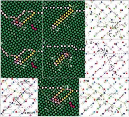
Fig.7.(a) Formation of the first fault changes the stacking sequence of basal planes from BABA to BCAC,similar to that caused by an fault with a b30 at the end (b-c).(d) Same as (a) but showing the transition of A→C of atomic columns in the plane lying two-basal-layer above the b30,and between column 4 (at position D) and the twin boundary.(e-f) An <> dislocation will form if column 4 stays at its original position (C0) between columns 3 and 5.(g) Displacement of column 4 from C0-C1,triggers the transition of A→C for columns lying the same basal plane as column 4,but moving to the twin lattice after column 4.The column 4 finally moves to position D between columns 6 and 7,in the middle of A and C positions.(h) The transition of A→C between column 4 and twin boundary,causes the formation of the second fault with the migration of the twin boundary.The second fault changes the stacking sequence of basal planes from BABA to BABC.(h,i) The formation of the two faults changes the stacking sequence of basal planes from BABABABA to BABCBCAC,giving rise to a F3 fault.In the polychromic complex,the red and dark blue lattices represent respectively the matrix and twin crystal.The green,purple and light blue lattices represent the crystals that have same orientation as the twin crystal,but with the stacking sequence changed by , and I1 faults,respectively.Atomic positions in two adjacent (20) planes are indicated by solid and open circles.

Fig.8.(a-b) Interaction between a migrating (101) twin boundary and a [02]B Frank partial produces an < > dislocation in the twin lattice.(c)The attractive force between the resultant < > and a b-2/-2 TD causes <> absorbed by the twin boundary.(d-e) A F3 fault is generated with further migration of the twin boundary.(f) The reaction in (b-e) can be described by <>+b-2/-2=b30+2b-1/-1, where < >=b30+b90.Three atoms are coloured in purple to illustrate the position change of atoms in (a-e).The orange solid and dashed lines on the twin boundary indicate the current and past boundary positions.The twin boundary migration direction is indicated by the white arrow in (a,b).
3.2.Effects of external stress on F3 formation
3.3.Effects of temperature on F3 formation
Simulations conducted at different temperatures,with the applied shear stress and the position of the matrix dislocation unchanged,indicate that the formation of a F3fault is also influenced by temperature.Under an applied shear stress that is in the range of 200 MPa to 800 MPa,the temperature was set to be in the range of 100–500 K,with an interval of 100 K.The interaction products are summarized in Table 3.It is found that,when the external applied shear stress is small or moderate (below 450 MPa),a F3fault prefers to form at low temperature(100 K and 200 K),while<>forms only at higher temperature (above 300 K).Therefore,the F3fault forms more frequently than the<>dislocation for the selected temperatures.However,when the applied shear stress is sufficiently large (above 600 MPa),the<>dislocation can form even at 100 K,and its formation frequency can overweigh that of the F3fault in the examined temperature range.
3.4.Effects of matrix dislocation location on F3 formation
Products obtained from the interaction between a (101) twin boundary and a [20]B or [02]B Frank partial dislocation under different shear stresses at 300 K.The matrix dislocation is kept at the same position in the simulation box for each simulation.Table 2
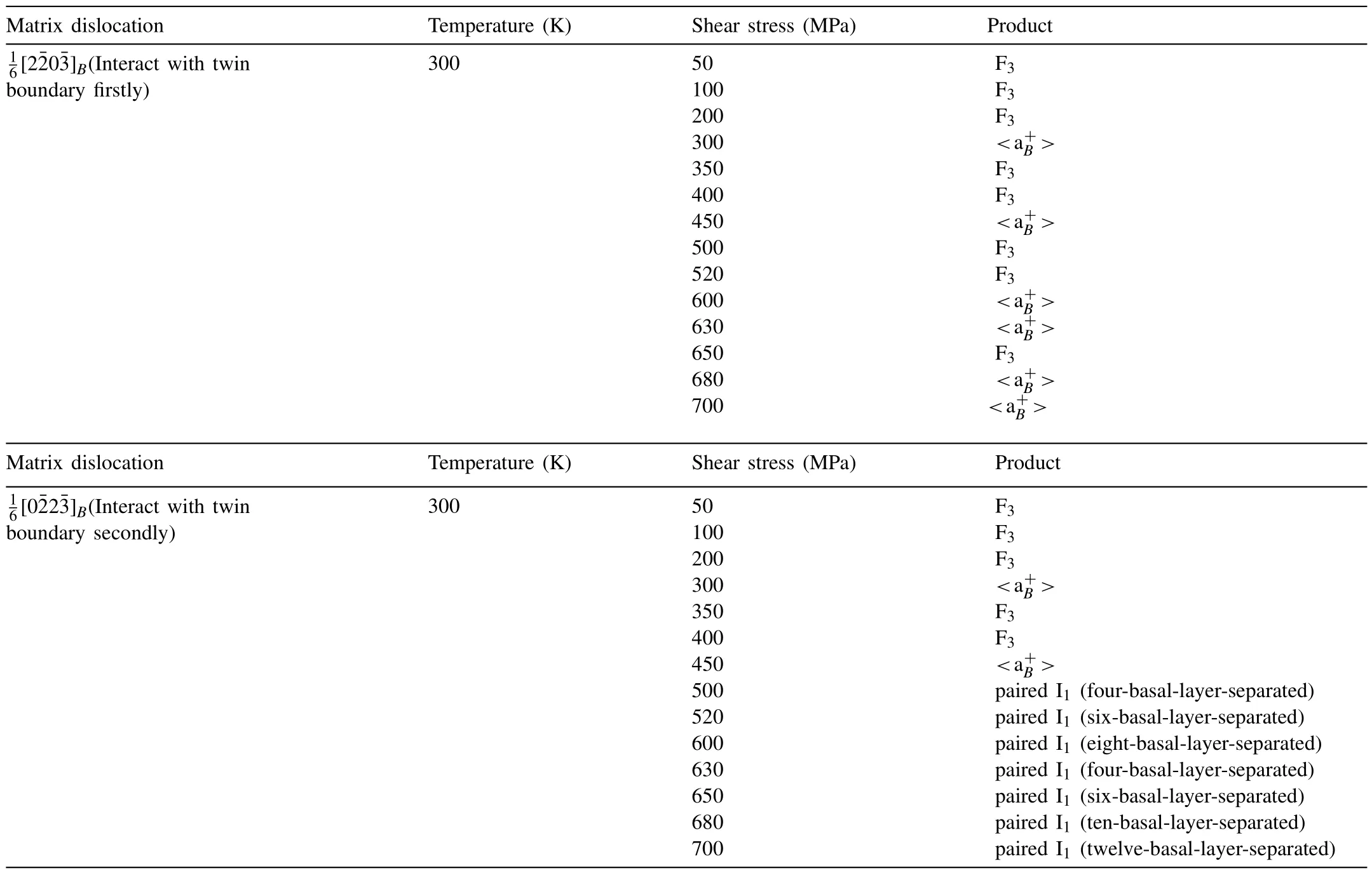
Products obtained from the interaction between a (101) twin boundary and a [20]B or [02]B Frank partial dislocation under different shear stresses at 300 K.The matrix dislocation is kept at the same position in the simulation box for each simulation.Table 2
4.Discussion
4.1.Formation mechanism of F3
A previous DFT work conducted by Han et al.[27]has mentioned the F3fault.The generation of the F3fault in their work is hypothetically claimed to be through sequential gliding of Shockley partials on successive basal planes.Such a process starts from the gliding a 90° shockley partial on a specific basal plane of an HCP lattice,giving rise to an I2fault that is associated with a stacking sequence change of BABCACAC.Subsequently,by gliding a 30° Shockley on the plane one-layer below the plane C (where the 30° Shockley is located) of the resultant I2fault,a T2fault associated with a stacking sequence change of BABCBABA forms.After that,by gliding another 90° shockley on the plane two-layer below the plane C of the resultant T2fault,an F3faut associated with a stacking sequence change of BABCBCAC is generated.
The interaction between the twin andcan also generate an<>dislocation,instead of a F3fault,under the same shear stress of 200 MPa at 300 K,but with the matrix dislocation placed at a different position of the simulation box.Simulation results presented in Tables 2 and 3 show that for a given temperature,F3is preferred to form than<>at a lower shear stress (below~400 MPa).As for a given shear stress,the F3is also preferred to form than<>at a lower temperature (100 K and 200 K).The formation of these two products depends on whether the displacement of atomic column 4 occurs on the twin boundary or not.It is shown that a F3fault is produced when the column 4 displaces from its original position to the position between the columns 6 and 7,Fig.11.If the column 4 stays at its original position,then the final product is an<>dislocation.It is also shown in Fig.11 that there is an energetic incentive for the displacement of column 4 on the twin boundary.As a result,when the twin boundary migrates at a low rate,under a lower shear stress and/or at a lower temperature,there is sufficient time for atomic column 4 to move to the energetic favored position on the twin boundary.This is followed by the change of the lying plane of the absorbed dislocation and the rearrangement of atomic positions around the location of the absorbed dislocation.Consequently,the F3fault forms in the twin lattice after the absorbed dislocation and the rearranged atoms detached from the twin boundary.However,when the twin boundary migrates at a higher rate,under a higher shear stress and/or at a higher temperature,there is insufficient time for the rearrangement of atoms around the location of the absorbed dislocation.In this case,the absorbed dislocation is quickly detached from the migrating twin boundary,with atoms around it remaining at their original positions.An<>dislocation forms consequently.Although the simulation results suggest a relatively high formation frequency of the F3fault at lower shear stress and/or lower temperature,experimental reports of the F3fault in Mg or its alloys are scarce.There are two possible reasons for this discrepancy.Firstly,there exists a significant difference in strain rates between experimental conditions(typically 10-3s-1)and those used in MD simulations(typically 108-1010s-1).Secondly,the initiation of interactions between (102)twin and

Fig.11.Formation of (a-c) a F3 fault and (d-f) an <> dislocation from twin and [02]B interaction.The configuration shown in (b) has a lower potential energy than that in (e),with a difference of 0.038 eV/nm.
Products observed from the interaction between a (101)twin boundary and a [20]B Frank partial dislocation at different temperatures and stresses.The matrix Frank partial is kept at the same position in the simulation box for each simulation.Table 3
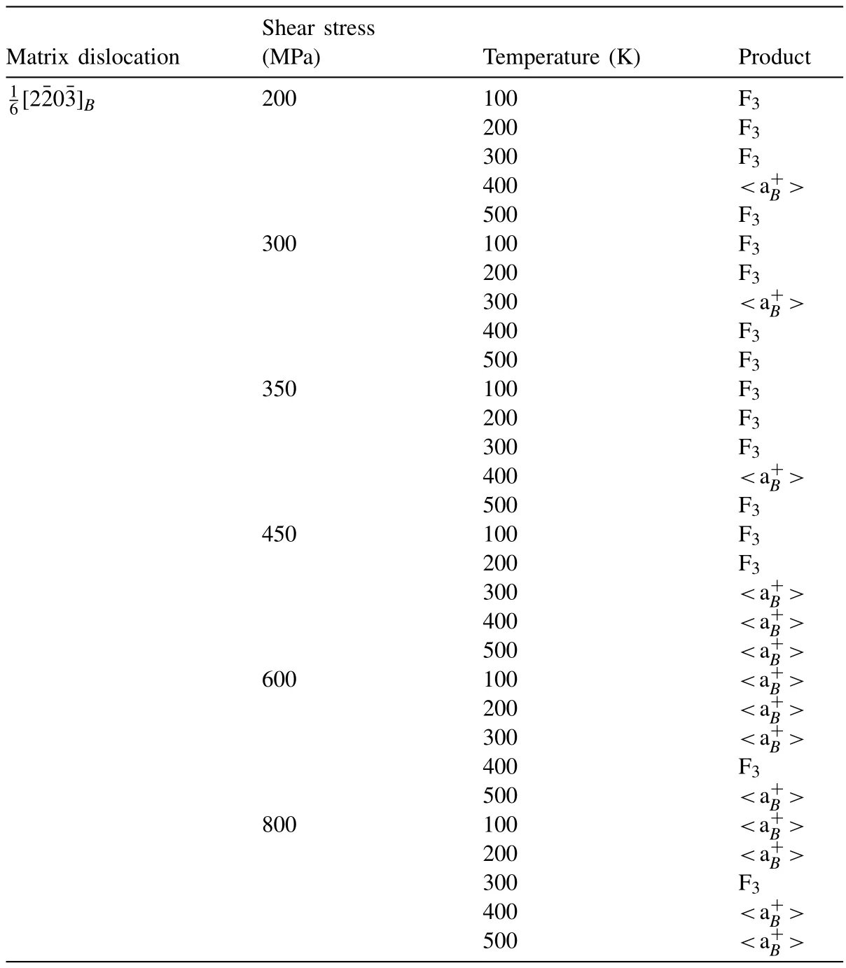
Products observed from the interaction between a (101)twin boundary and a [20]B Frank partial dislocation at different temperatures and stresses.The matrix Frank partial is kept at the same position in the simulation box for each simulation.Table 3
4.2.Similarities and differences between F3 with other basal stacking faults
The F3fault changes the stacking sequence of basal planes from BABABABA to BABCBCAC in HCP lattice.Its character is similar to the intrinsic fault F3in an FCC lattice,which changes the stacking sequence from BCABCABCA to BCABCBCAB [2,54].The F3fault comprises two I1faults that are separated by two basal layers and have the same character,i.e.,the shear directions that generate these two I1faults are the same,Fig.13a.A T2fault [5,27,29]can also be regarded as comprising two I1faults,but these two I1faults are separated by a single basal layer and have different characters,i.e.,the shear directions that generate these two I1faults are opposite,Fig.13b.F3fault changes the stacking sequence of basal planes from BABABABA to BABCBCAC,and the net outcome is similar to the stacking sequence change of basal plane from BABABA to BABCAC that is caused by an I2fault [1–4],Fig.13c.A comparison of the F3and I2faults,together with the T2fault that changes the stacking sequence from BABABA to BACABA [1,4,5],and the I1fault that changes the stacking sequence of basal planes from BABABA to BABCBC [1-4],is provided in Fig.13.

Fig.13.Comparison of characters of different types of basal stacking faults: (a) F3,(b) T2 (c) I2,and (d) I1.The plane that has its two neighbouring planes in different labels is indicated in blue dashed line.The blue solid line indicates the shear direction that generates the I1 or I2 fault.
The end of an I1fault is bounded by a Frank partial dislocation [4,6],the end of an I2fault is bounded by a Shockley partial dislocation [4,21],the end of a T2fault is bounded by neither Frank nor Shockley partial dislocation [5],and it is immobile.For a F3fault,its end is bounded by a complex lattice defect with a Burgers vector identical to ab30Shockley partial,similar to that for an I2fault,Fig.14.It is found in our work that the defect at the end of a F3fault can decompose into ab30Shockley and a T2fault at a higher temperature (above~400 K).Glide of thisb30along [010]telongates the length of the decomposed T2fault,Fig.15a-b;Glide of thisb30along [100]tgenerates an I2fault between theb30and the T2fault,Fig.15c-d.

Fig.14.Comparison of characters of the ends of different types of basal stacking faults: (a) F3,(b) T2 (c) I2,and (d) I1.
There exists a close relationship between the F3and I2or T2faults.As shown in Fig.16a,the formation of a T2fault,by displacing atomic columns from A positions to C positions (with a displacement ofwithin a single basal plane),changes the stacking sequence of basal planes from BABABABA to BABCBABA.The glide of ab30Shockley on the plane lying two basal layers below the plane C of the T2,causes this plane and all the planes below experience a transition of A→C and B→A.As a result,the stacking sequence is changed from BABCBABA to BABCBCAC,giving rise to a F3fault.As shown in Fig.16b,if there is an I2fault formed by gliding ab30Shockley,the stacking sequence of basal planes will be changed from BABABABA to BABABCAC.Displacing the atomic columns byon the plane lying two basal layers above the plane C (where theb30is located) of the I2,changes the stacking sequence from BABABCAC to BABCBCAC,generating a F3fault.The polychromic complex in Fig.16c suggests that a F3fault can be produced where a T2and an I2both exist,with the plane C of the T2lying two basal layers above the plane C of the I2.Based on DFT calculations,the stacking fault energy of an I2fault in pure Mg was reported to be 34 mJ/m2[55],which is almost two times of the energy for an I1fault (18 mJ/m2[55]).The energy of a F3fault was calculated to be 33 mJ/m2in the DFT work of Han et al.[27],and it is calculated to be 34 mJ/m2in the present MD work.The energy of a T2fault was calculated to be 41 mJ/m2by DFT in the work of Liu et al.[5].It is noted that the fault energy of a F3is similar to that of an I2fault,and that the energy difference between T2and I2faults is small.These similar energy values of the F3,I2and T2faults indicates the generation of one fault from another is likely to be energetically easy.
The essence of these two reactions is the same,and is different from that of a reaction to generate a F3fault(Fig.17g-h),which can be described by:

Fig.17.Illustration of the formation of (a-c) a T2 fault that connects with an fault,(d-f) an fault,from twin and [20]A interaction,and (g-h) a F3 fault from the twin and [20]B interaction.The Burgers vector relationship of lattice dislocations and disconnections for (a-c) or (d-f) is illustrated in(i),for (g-h) is illustrated in (j).The process (a-b) occurs when a shear stress of 400 MPa and a compression stress of 300 MPa is applied simultaneously at 300 K.The process (d-e) and (g-h) occur when only a shear stress of 200 MPa is applied at 300 K.
4.3.Distinction between F3 and paired I1 faults separated by multiple basal layers
For two I1faults,they can be separated by an odd or even number of basal layers.If these two I1faults are separated by an odd number of basal layers,the shear directions that are associated with these two I1faults must be opposite (and).In contrast,when the two I1faults are separated by an even number of basal layers,the shear directions that generate these two I1faults must be the same (and).These are geometric requirements,as illustrated in Fig.18.When two I1faults are separated by a single basal layer,their arrangement is essentially a T2fault.The formation of a T2fault leads to a twin-like arrangement of basal planes with respect to the plane C.For two I1faults separated by other odd (except one) number of basal layers,if one fault is associated with a stacking sequence of BABCB (),then the other fault must be associated with a stacking sequence of BCBAB ().The basal planes are symmetrically arranged with respect to the region between the two I1(and)faults and the stacking sequence is changed from ABAB to BABA after passing through the two I1faults,similar to the case of a T2fault.For two I1faults separated by even number of basal layers,if one of the two faults is associated with a stacking sequence of BABCB (),then the other fault must be associated with a stacking sequence of CBCAC ().In this case,the stacking sequence of basal planes is changed from ABAB to CACA after passing through the two I1faults(and).When the two I1faults are separated by two basal layers,their arrangement is essentially a F3fault.

Fig.18.Stacking sequence change associated with two I1 faults that are separated by different basal layers and different shear directions.An and an faults are separated by one,three,and five basal layers are shown in (a),(c) and (e),respectively.Two I-1 faults are separated by two,four and six basal layers in (b),(d) and (f),respectively.The plane that has its two neighbouring planes in different labels is indicated in blue dashed line.The blue solid line indicates the shear direction that generates the or fault.
The F3fault comprising two I-1 faults that are separated by two basal layers is generated from the interaction between a migrating(102)twin boundary anddislocation.Apart from the F3fault,paired I1faults separated by other even numbers of basal layers (four,six,or even twelve) are also observed in our simulation work.They are generated when decomposition of aFrank partial occurs before the twin-dislocation interaction starts,which requires larger shear stress compared to that for the generation of a F3fault.An example of the paired I1faults that are separated by twelve basal layers is shown in Fig.19.These paired I1faults change the stacking sequence from BABABABABABABABABA to BABCBCBCBCBCBCBCAC,and have their ends bounded by a complex defect with a Burgers vector equal to ab30in the twin lattice.Paired I1faults with six-basal-layer separation distance was also observed in the MD simulation conducted by Zhou et al.[25].In their work,decomposition of a Frank partial of a prismatic

Fig.19.Paired I1 faults comprising two faults separated by twelve basal layers generated from the twin-dislocation interaction in MD simulation.The ends of the paired I1 faults are connected to two separate BP b-1/-1 disconnections on the twin boundary in (a) and bounded by a lattice defect with a Burgers vector equal to a b30 in (b).
For a F3and paired I1faults that are separated by other even basal layers,they have similar character,i.e.,with one end connected with twob-1/-1and the other end bounded by a defect with a Burgers vector identical to ab30.The stacking fault energies are assumed to be the same for the F3and the paired I1faults that are separated by other even basal layers,since they are all composed of twofaults.However,the defect at the end of the F3and the paired I1faults that are separated by other even basal layers,causes different volumetric strain and energy.It is calculated that the volumetric strain and the potential energy around the end of the F3fault is smaller than that around the end of the paired I1faults,and they increase with the increase of the separation distance between the paired I1faults,Fig.20.This indicates that a configuration comprising a F3fault is energetically more favoured than that comprising paired I1faults that are separated by other even basal layers.
4.4.Transitions between different types of basal stacking faults
For the F3stacking fault investigated in our work,its end that is bounded by a complex lattice defect can decompose into ab30and a T2fault at temperatures above 400 K.The glide of theb30along the [010]tor [100]tdirection can elongate the T2fault or produce an I2fault between theb30and T2,as shown in Fig 15.The transformation between F3and T2or I2faults can be controlled by adjusting temperature and applied stress.Specifically,when the external applied stress has a larger component along the [010]or [100]direction in the twin crystal,F3tends to transform to T2or I2fault,especially at temperatures above 400 K.
Transitions between I2,T2and F3faults have also been reported in the DFT work conducted by Han et al.[27].These transitions are thought to occur through a sequential faulting mechanism illustrated in Fig.21a.Starting from an ideal HCP Mg crystal,shearing the lattice from a specified plane and below by(which is equivalent to the glide of a 90°Shockley on this plane) results in an I2fault,which can further transform into a T2fault by shearing the resultant lattice from the plane one layer below the specified plane by(equivalent to gliding a 30° shockley).Similarly,shearing the resultant lattice from the plane two layers below the specified plane by(equivalent to gliding another 90°Shockley)generates an F3fault.The transitions between these stacking faults are determined by the generalized stacking fault energy(GSFE) pathways [27],as shown in Fig.21b.The stable SF energies corresponding to I2,T2and F3are denoted byγi2,γt2,γf3,respectively,while the unstable stacking fault energies defined by the saddle points along the pathways are denoted byγus1,γus2,γus3,respectively.Han et al.[27]suggested that the sequential faulting,such as the generation of an I2fault from an ideal HCP,is more likely to occur with decreasingΛ1≡γi2/γus1or withΛ2≡(γus2-γi2)/ (γus1-γi2)close to 1.Therefore,the transition between I2,T2and F3faults can be controlled by adjustingΛ1orΛ2,which can be achieved through the addition of alloying elements in Mg.For example,it has been reported that alloying Li tends to increase the SF energies along the faulting pathways shown in Fig.21b,while alloying Al decreases these SF energies,thus facilitating the transitions from I2to T2and from T2to F3[27].
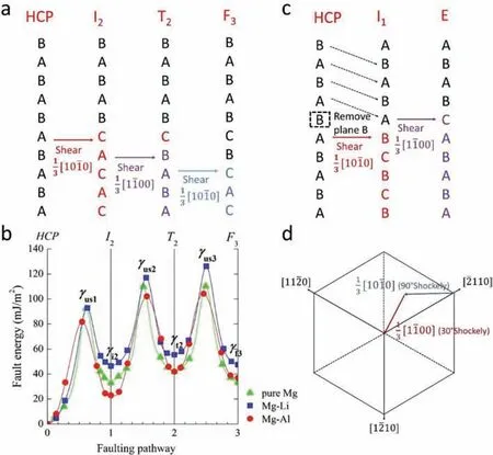
Fig.21.(a) Schematic illustration of sequential faulting mechanism for the generation of I2 fault from ideal Mg crystal,followed by the generation of T2 from I2 and then F3 from T2.(b) GSFE curves of Mg (indicated by green triangle),Mg-Li alloy (indicated by blue square) and Mg-Al alloys (indicated by red circle) along the pathways HCP-I2-T2-F3 [27].(c) Schematic illustration for the generation of I1 fault from an ideal Mg crystal,followed by the generation of E fault from I1.(d) Schematic illustration of the top view of the Mg crystal,with indicated shears of [100](Burgers vector of a 90° Shockley partial)and [100](Burgers vector of a 30° Shockley partial).
For the transition between extrinsic E fault and other faults,Shang et al.[29]suggested that the E fault can form from an I1fault in a similar manner to how a T2fault is generated an I2fault.As shown in Fig.21c,an intrinsic I1fault associated with a stacking sequence change of BABABCBC can be formed from an ideal hcp crystal by removing a B plane above a specified plane A,followed by shearing the lattice from the specified plane and below by.Consequently,an E fault associated with a stacking sequence change of BABCABAB can be formed by shearing the resultant lattice one-layer above the specified plane by.Similar to the sequential faulting mechanism proposed by Han et al.[27],the transition from I1to E also depends on the GSFE pathway,and its occurrence is influenced byΛ1orΛ2.It is possible that this transition can be controlled by adjusting the alloying elements in Mg,similar to the transition from I2to T2and from T2to F3which was proposed in the work of Han et al.[27].However,this aspect requires further investigation based on DFT calculations.
4.5.Potential impact of F3 faults on mechanical properties
The plastic deformation capability of Mg can be enhanced by the interaction between(102)twins and

Fig.22.F3 fault has its length elongated when the twin boundary migrates upward,with the defect at its end in the twin crystal immobile.The white arrow in (a) indicates the migration direction of the twin boundary.One atom is indicated in purple to illustrate the atomic position change from (a) to (b).”
5.Conclusions
An unusual basal stacking fault designated F3has been observed for the first time in magnesium in molecular dynamics simulations of interactions between a migrating(102)twin boundary and prismatic
Declaration of competing interest
The authors declare that they have no known competing financial interests or personal relationships that could have appeared to influence the work reported in this paper.
Jian-Feng Nie is an editorial board member for Journal of Magnesium and Alloys and was not involved in the editorial review or the decision to publish this article.All authors declare that there are no competing interests.
Acknowledgments
JFN gratefully acknowledges the support from the Australian Research Council (DP200102985).YY is grateful to the Monash Graduate Scholarship and International Postgraduate Research Scholarship.YY and JFN also acknowledge computational resources provided by the Australian Government through NCI-Gadi and Pawsey-Magnus under the National Computational Merit Allocation Scheme.
 Journal of Magnesium and Alloys2023年7期
- Journal of Magnesium and Alloys的其它文章
- Recent progress in MgB2 superconducting joint technology
- “Smart” micro/nano container-based self-healing coatings on magnesium alloys: A review
- Recent advances using equal-channel angular pressing to improve the properties of biodegradable Mg–Zn alloys
- Twin evolution in cast Mg-Gd-Y alloys and its dependence on aging heat treatment
- Effects of Ce content on the modification of Mg2Si phase in Mg-5Al-2Si alloy
- Solute drag-controlled grain growth in magnesium investigated by quasi in-situ orientation mapping and level-set simulations
