Microstructure characteristics and mechanical properties of Al/Mg joints manufactured by magnetic pulse welding
Congong Zhu ,Shiwei Xu,,* ,Wenli Go,** ,Yifn Meng ,Sen Lin ,Lu Di
a College of Materials Science and Engineering,Hunan University,Changsha 410082,China
b State Key Laboratory of Advanced Design and Manufacturing for Vehicle Body,Hunan University,Changsha 410082,China
c Beijing Spacecrafts,Beijing 100094,China
Abstract The effective connection of 1050 Al and AZ31 Mg was realized by magnetic pulse welding.The maximum tensile-shear force of the dissimilar Al/Mg metal lap joint reached 97% of that of the 1050 Al alloy base material by optimizing the process parameters.The microstructure of dissimilar Al/Mg welded joints was analysed by Scanning Electron Microscope (SEM),Energy Dispersive Spectrometer(EDS) and Electron Backscattered Diffraction (EBSD).The results show that the key to obtaining high shear strength of Al/Mg dissimilar metal joints is mainly due to the following two reasons.On the one hand,grain refinement and element interdiffusion occur at the interface.On the other hand,no intermetallic compounds are formed at the interface.
Keywords: Al/Mg dissimilar materials;Magnetic pulse welding;Mechanical properties;Interface;EBSD.
1.Introduction
The effective welding of aluminum (Al) alloys and magnesium (Mg) alloys has become one of the key issues that limits their lightweight applications in aerospace,transportation,packaging,printing,and electronics industries and 3C products [1–3].The crystal structures of Al and Mg are face-centered cubic(FCC)and hexagonal close-packed(HCP)structures,respectively.According to the Al–Mg binary phase diagram,it can be seen that brittle intermetallic compounds are easily formed between Al and Mg.Therefore,the highquality and efficient connection of dissimilar Al and Mg metals has always been a technical problem in welding [4,5].In recent years,many studies have been conducted on diffusion welding (DW) [6–8],friction welding (FW) [9–11],friction stir welding (FSW) [12–14],resistance spot welding (RSW)[15,16],tungsten inert gas(TIG)welding[17,18],laser beam welding (LBW) [19],explosive welding (EW) [20],and magnetic pulse welding (MPW) [21–24]for dissimilar Al and Mg metal joints.The main limitation of their use is the welding strength of dissimilar Al/Mg metals is the presence of Al12Mg17or Al3Mg2intermetallic compounds (IMCs) during welding[25].Contact between Al and Mg liquids is inevitable during fusion welding,so it is difficult to control the formation of IMCs.By solid phase welding,such as DW,EW,and MPW,dissimilar Al/Mg metal joints with a certain strength can be obtained.However,the joint performance is limited due to the existence of IMCs,and further improvements and adjustments are needed to improve the joint performance to meet application requirements.
MPW is a solid phase welding method similar to explosive welding and impact welding and is environmentally friendly and efficient,so it has received substantial attention recently[26–33].MPW can be used to realize the successful connection of various dissimilar materials,such as Al/Fe [27,28],Al/Cu [29],Al/Ti [30]and Al/Mg [21-24,31-33].Some researchers have studied the MPW interface characteristics of dissimilar Al/Mg alloys.Sternet al.[21]found a typical wave pattern with an average thickness of 20 μm at the Al/Mg MPW interface.Chen et al.[24]found that IMCs exist at the Al/Mg MPW interface.Marya et al.[33]found that the Al/Mg MPW joint has no heat-affected zone,and it shows discontinuous pockets or a continuous microscopic interface layer at the interface.The use of MPW technology can effectively avoid the formation of defects,such as cracks and pores,and occurrence of segregation during fusion welding and obtain high performance dissimilar metal joints with excellent interfacial bonding.However,research on the relationship between the high performance of Al/Mg MPW joints and the interface structure is not systematic.In this work,the microstructure and mechanical properties of Al/Mg MPW joints were tested and analysed.The key factors responsible for obtaining high-performance Al/Mg MPW joints were examined and discussed,which laid a foundation for improving Al/Mg welding performance and meeting application requirements.
2.Material and methods
The flyer plate and parent plate used in this work are 1050 Al alloy and AZ31 Mg alloy with thicknesses of 1.5 mm.The Al and Mg sheets were cut into pieces with dimensions of 35 mm (width) × 120 mm (length).The schematic diagram of the sample size and placement position is shown in Fig.1.

Fig.1.Schematic diagram of specimen size (Unit: mm).
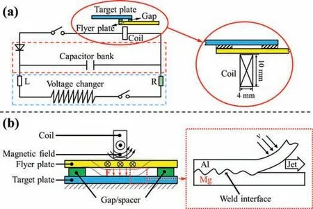
The welding areas of the specimens were first ground by abrasive paper to remove the oxide film and then cleaned by ethanol before MPW.The MPW equipment used in this work was produced by PST Company and exhibited a maximum discharge voltage of 16 kV and a maximum discharge energy of 48 kJ.A single turn coil with the cross section of 4 ×10 mm was employed in the welding process.The schematic diagrams of MPW welding process are shown in Fig.2.The high-frequency pulse current passed through the coil when the welding switch was closed.A strong magnetic field was generated around the coil.The flyer plate generated an induced current in the magnetic field,which was opposite direction to the current in the coil.Therefore,the flyer plate would be subjected to huge electromagnetic force.Results y electromagnetic force to collide the target plate at high speed to achieve welding.

Fig.2.The schematic diagram of MPW (a) Schematic diagram of magnetic pulse generator;(b) Schematic diagram of MPW process.
Different discharge energies and standoff distances were selected in the MPW experiments,the detailed experimental arrangement is shown in Table 1.Each experiment under the same parameters was repeated for three times.

Table 1The detailed process parameters of MPW in this study.
The mechanical properties of the MPW lap joints were evaluated by tensile-shear tests,which were performed with a travel speed of 2 mm/min at room temperature by using a tensile testing machine (Instron 5985 testing machine).The sample used to observe the weld interface was cut from the Al/Mg MPW joint with discharge energy of 35 kJ and standoff distance of 1.4 mm.The schematic diagram of the sampling location is shown in Fig.3.The microstructures evolution was characterized by optical microscopy (OM),scanning electron microscopy (SEM,Zeiss sigma 300) with energy dispersive spectroscopy (EDS) and electron backscatter diffraction(EBSD).And the step size for EBSD mapping was 0.5 μm.

Fig.3.The schematic diagram of the sampling location.
The deformation of the flyer plate during MPW process was a dynamic process,so it was difficult to obtain the collision parameters when the flyer plate collided with the target plate.Therefore,the FEM-BEM sequential coupling method was used to simulate the deformation process of the flyer plate during MPW process in this study.The detailed modeling and simulation process could refer to the research results of Ref[34].The smoothed particle hydrodynamic (SPH) simulation was used to simulate the distribution of physical quantities such as stress,strain,and temperature at the wave interface in the Al/Mg MPW joint.The collision velocity and collision angle obtained by FEM-BEM simulation were used as initial conditions to establish a SPH model of the collision process[35].The collision velocity and collision angle in SPH simulation were set to approximately 420 m/s and 14.5°,respectively.The schematic diagram of the SPH model is shown in Fig.4.

Fig.4.The model in SPH simulation.
The wave interface obtained by SPH would be compared and analyzed with the microstructure observation results to verify the accuracy of model.The temperature field distribution obtained by SPH was combined with the microstructure characterization results for analysis to reveal the interface characteristics of Al/Mg MPW joint.LS-DYNA was selected as the simulation solver in this study.The Johnson-Cook model was used in this paper to describe the dynamic mechanical behavior of Al and Mg alloy under high strain rate deformation process.The Johnson-Cook model can be described in Eq.(1) [36]:
Whereσis the equivalent strain;εis the plastic strain;A is the yield strength at the reference temperature;n is the strain hardening index;C is the strain rate sensitivity coefficient;=/is the dimensionless quantity relative to the reference strain rate;andT*=(T-Tr)/(Tm-Tr) in whichTris the reference temperature,andTmis the melting temperature of the material.Table 2 and Table 3 show the material properties and Johnson–Cook parameters of flyer plate and target plate,respectively [37,38].

Table 2Material properties of 1060 Al and AZ31 Mg.

Table 3Johnson-Cook parameters of1060 Al and AZ31 Mg.
The Mie-Gruneisen equation of state (EOS) was used to define the collision pressure at the collision point during MPW process in this study,and its expression is as follows:
Wherecis the intercept of the Hugoniot curve of the corresponding material,s1,s2is the dimensionless coefficient of the slope of the Hugoniot curve,γ0is the Gruneisen constant,ρandρ0are the actual density and initial density of the particles,respectively.The coefficients of the EOS for Al and Mg are shown in Table 4 [39,40].

Table 4Coefficients of Mie-Gruneisen EOS for 1050 Al and AZ31 Mg.
3.Results and discussion
The flyer plate was driven by electromagnetic force to collide with the target plate at high speed in the MPW process.A jet was generated and severe plastic deformation occurred at the collision point.The jet scoured the dirt and oxide layer on the surface of two metal plates,so that the clean metal surfaces were tightly combined under high pressure to achieve welding.The 1050 Al alloy and AZ31 Mg alloy were successfully joined by MPW in this work.The tensile-shear test was carried out to evaluate the mechanical properties of Al/Mg joints under different process parameters.
Fig.5(a) presents the load–displacement curves of Al/Mg joints prepared with different discharge energies and standoff distances during the tensile-shear test.The maximum tensileshear force increased first and then decreased with the increase of discharge energies when the standoff distance was constant at 1.4 mm.When the discharge energy was 35 kJ,the maximum tensile-shear force also exhibited a similar trend with the increase of the standoff distances.The most effective welding was obtained (that is,the maximum tensile-shear force is attained) at the discharge energy of 35 kJ and standoff distance of 1.4 mm,resulting in a tensile-shear force that is 97% of that of the base Al alloy.This means that MPW can produce dissimilar Al/Mg alloy components with good mechanical properties.In this study,the ratio of the joint strength to the base metal strength is defined as the joint effectiveness.The joint effectiveness of pure Al and AZ31 Mg alloy achieved by different welding methods is summarized in Fig.5(b).As shown,FW,FSW and other welding methods can achieve Al/Mg welded joints with strengths up to 86% of the Al base metal.However,by optimizing the process parameters in this work,the strength of Al/Mg MPW joints can reach 97% of that of the Al base metal.The joint effectiveness of Al/Mg MPW joints far exceeds that achieved by other welding methods.

Fig.5.The mechanical properties comparison of Al/Mg joints: (a) the load–displacement curves of Al/Mg welded joints under different welding process parameters;(b) the joint effectiveness of dissimilar Al/Mg metals achieved by different welding methods.
The schematic diagrams of the tensile-shear test and failure modes of the welded joints are shown in Fig.6(a).The failure modes of the joints could be divided into three categories: failure in the welded zone (defined as mode 1),failure in the necking deformation zone on the Al side (mode 2) and failure in the impact zone on the Mg side (mode 3).Corresponding practical photos of the failed welded joints are given in Fig.6(b~d).
The failure types of Al/Mg magnetic pulse welded joints after tensile-shear test under different process parameters are shown in Table 5.When the discharge energy is small,the welded joint is broken at the weld in the tensile-shear tests(failure in mode 1).When the discharge energy or standoff distance is too large,the Mg alloy receives a violent impact,reducing its strength.The welded joint will break at the impact zone on the Mg side,which is failure in mode 3.It can provide enough speed for the flyer plate to collide with the target plate when the energy reaches 35 kJ,thereby obtaining a high-performance welded joint.This is the case for the maximum tensile-shear force,the welded joint will be broken at the necking deformation zone on the Al side (failure in mode 2).This indicates that the strength of weld joints could almost reach that of the base material.

Table 5The failure modes of Al/Mg MPW joints after tensile-shear test under different process parameters.
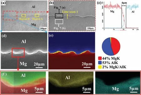
In order to explore the reasons for the high quality of welded joints in more detail,OM,SEM and EBSD were used to characterize and study the microstructure evolution of welding interface under the process parameters of 35 kJ-1.4 mm.Fig.7 is the typical morphology and element distribution at the welding interface of joint with 35 kJ-1.4 mm.Fig.7(a) shows that the interface structure of the Al/Mg joint is composed of wave and flat interfaces.No welding defects,such as cracks or oxides,were found at the interface,and no IMC layers formed.According to previous studies [26–33],a wave interface can usually lead to the high strength of joints.The enlarged micrograph of the wave interface is shown in Fig.7(b).It can be seen from Fig.7(b) that the waveform sizes of the welding interface are different,which is because the collision angle and collision speed of the MPW process are dynamically changed [22].In addition,Fig.7(b)shows that the waveform of the Al/Mg MPW interface is not a sine wave,which is due to the different hardness values of the two welding base materials.It can be seen from the EDX line scan analysis result at the waveform interface in Fig.7(c)that Al and Mg diffused approximately 4 μm at the welding interface [31].The SEM micrograph of the typical waveform interface (enlarged view of the blue box area in Fig.7(a)) is shown in Fig.7(d).The phase distribution of the wave interface shows that elemental diffusion occurs at the interface in Fig.7(b).The diffusion distribution of Al and Mg is shown in Fig.7(c).Al and Mg have diffused and merged,but no IMCs were formed at the interface [23].

Fig.7.(a) Typical morphology of the Al/Mg MPW joint interface;(b) Enlarged view of the red box area in Fig.7(a);(c) The EDX line scan along the yellow arrow in Fig.7(b);(d) The typical waveform interface of the Al/Mg MPW joint,corresponding to the blue box area in Fig.7(a);(e) Phase distribution in the area of Fig.7(d);(f) Elemental distribution of the area marked by a red box in Fig.7(d);.
Fig.8(a) and 8(b) shows OM images of the waveform interface and the Mg side near the interface,respectively.Fig.8(c) shows the microstructure of the Mg base metal.The grains near the interface in Fig.8(a) are not clear,which may be due to stress concentration that occurred due to severe plastic deformation during MPW [23].By comparing Fig.8(b) with Fig.8(c),it is obvious that the grains have been refined to a certain extent.The magnified micrograph of the Mg side near the interface is shown in Fig.8(d).It can be clearly seen that many twins formed in the grains.

Fig.8.(a) OM image of the wave interface of Al/Mg MPW joint;(b) OM image of the Mg side near the interface;(c) OM image of the Mg alloy base material;(d) Enlarged view of the red box area in Fig.8(b).
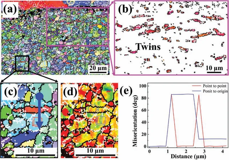
The microstructures of the Mg base metal,flat interface(region A in Fig.7(a)) and wave interface (region B in Fig.7(a)) of the Al/Mg MPW joint were further examined by EBSD and are shown in Fig.9.The dark pixels in these figures indicate low overlapping confidence index (CI)values.It can be seen from Fig.9(a)that the average grain size of the Mg alloy base metal is 3~4 μm.Unlike Fig.9(a),Fig.9(b)and 9(c) shows grain refinement at the interface.Great stress concentration is also found at the wave interface in Fig.9(c),which leads to the grains on the Mg side not being recognized clearly.Fig.9(d) and 9(e) displays the texture of the Mg alloy base material and the Mg region near the flat interface.Unlike the Mg base metal,lamellar structures,i.e.,structures with many twins,are found near the flat interface,which is the main reason for grain refinement and texture weakening.Fig.9(f) and 9(g) shows the kernel average misorientation (KAM) maps,which indicate the stress concentration distribution of the flat interface and the wave interface of the Al/Mg welded joint,respectively.Higher KAM values are observed at the wave interface than that at the flat interface(Fig.9(g)),which means that more stress concentrates at the wave interface than at the flat interface,indicating that more severe plastic deformation occurred at the wave interface.
The KAM information could indicate that plastic deformation at the flat interface is not as severe as that at the wavy interface.As shown in Fig.9(c),the colours of the grains near the wavy interface on the Mg side are somehow different than those of the initial grains in both Fig.9(a) and 9(b),but many grains show colours similar to those of the twinned parts in Fig.9(b) and 9(i).At the wave interface,tension twins may first generate and they widen and consume the initial grains to form new grains as plastic deformation progresses.The shear strain at the wavy surface causes severe plastic deformation and leads to a high dislocation density inside the grains.Therefore,more obvious grain refinement and stress concentration occur near the wave interface than near the flat interface,which is also the reason for the unclear grains near the wave interface in Fig.9(c).
Fig.10 illustrates the characteristics of twins in the grains on the Mg side of the flat interface in detail.After collision occurs in MPW,there are many twins inside the grains near the flat interface on the Mg side,as shown in Fig.10(h) and(i).Fig.3(j) shows an enlarged view of the black box in Fig.3(h).Fig.3(k) presents the KAM image of the corresponding area of Fig.3(j).The stress distribution in grains with twins is smaller than that in other grains.This is because the generation of twins consumes energy and releases concentrated stress.Fig.3(l) shows the variation in the misorientation angle measured along the blue arrow in Fig.3(j).A drastic change is presented,and a large misorientation angle of~86° is observed across the twin boundaries,which can confirm that the twins in Fig.3(l) are {10–12} tension twins [41].The formation of {10–12} twins could fragment the grains,resulting in grain refinement,and could lead to basal pole tilt from ND and result in a new intensity peak at the center of the (0001) pole [42].As shown in Fig.3(e),the maximum intensity weakens the texture from 9.3 to 6.5.It is reported that {10–12} tension twins usually appear in the early stages of deformation [43].

Fig.10.The characteristics of twins in the grains on the Mg side of the flat interface: (a) EBSD image of the flat interface of an Al/Mg welded joint;(b)twin distribution in the area marked with a box in Fig.9(b);(c) enlarged view of the area marked by a black box in Fig.9(a);(d) KAM image of the corresponding area of Fig.9(c);(e) the misorientation angles measured along the blue arrow in Fig.9(c).
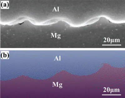
To further explore the change law of the microstructure at the interface,the distribution of temperature,stress and strain at the interface were simulated and calculated.Fig.11 compares the SPH simulation of the wave morphology in the Al/Mg interface and the SEM image of wave interface at Al/Mg MPW joint.The wave in the SPH simulation result is basically the same as the wave in SEM image,which illustrates the accuracy of the simulation model to a certain extent.

Fig.11.Comparison of SPH simulation and experimental results of wave interface at Al/Mg MPW joint: (a) SEM image of the Al/Mg interface;(b)SPH simulation of the Al/Mg interface.
Fig.12 shows the distribution of strain,stress,pressure,and temperature at the wave interface obtained by SPH simulation.It can also be seen from Fig.12(a~c) that the strain,stress,and pressure near the wave interface are much higher than those at the other parts,which is consistent with the large stress concentration at the wave interface observed in the experiment.The stress concentration phenomenon at the wave interface in Fig.12(b) also further explains the reason for the low EBSD signal value (Fig.9(c)) at the wave interface.The simulation results also show that the interface temperature could reach the melting temperatures of Al and Mg (as shown in Fig.12(d)),but no IMC layer forms at the interface.This is because it takes a certain amount of time to form Al12Mg17and Al2Mg3[44,45].Although the temperature at the interface has reached the melting temperatures of Al and Mg,the temperature drops very quickly at the interface,which does not provide enough time to form IMCs[36].

Fig.12.The results in SPH simulation:(a)The effective strain distribution in the wave interface calculated by SPH simulation;(b)Von Mises stress distribution in the wave interface calculated by SPH;(c) The pressure distribution in the wave interface calculated by SPH simulation;(d) temperature distribution in the wave interface calculated by SPH simulation.
The wave interface of the Al/Mg joint formed by MPW could achieve a certain degree of mechanical interlock,which is one of main reasons for the excellent joint performance (as shown in Figs.7(d) and 8(a)).Due to severe plastic deformation,grain refinement occurs at the interface (as shown in Fig.9(b) and (c)),which is also a main reason for the excellent performance of the Al/Mg MPW joint.According to the simulation results,the interface temperature has reached the melting temperature,but no IMCs formed due to the highspeed cooling rate,which is another main reason for the excellent performance of the Al/Mg MPW joint.
4.Conclusions
In the present work,Al and Mg alloys were successfully joined by MPW.The tensile-shear force of Al/Mg MPW joint can reach 97% of that of the Al base metal with a welding energy of 35 kJ and standoff distance of 1.4 mm by optimizing the process parameters.The mechanisms responsible for the excellent performance of Al/Mg MPW joints have been studied in detail.The results show that MPW not only forms mechanically interlocked waveforms and refines the grains due to plastic deformation at the interface but also causes the elements at the interface to diffuse to achieve metallurgical bonding.The temperature of the welding interface has reached the melting temperature,but no IMCs formed at the interface due to the extremely fast cooling rate.
Data availability
The raw/processed data required to reproduce these findings cannot be shared at this time due to technical or time limitations.
Conflict of interest
We declare that we do not have any commercial or associative interest that represents a conflict of interest in connection with the work submitted.
Acknowledgment
This work was supported by National Natural Science Foundation of China (No.51474101,51975202)and the equipment pre-research project of China (Nos.41422060204),the Natural Science Foundation of Hunan Province (2019JJ30005).And we are grateful to Prof.Junjia Cui for his guidance and help in this experiment.
 Journal of Magnesium and Alloys2023年7期
- Journal of Magnesium and Alloys的其它文章
- Recent progress in MgB2 superconducting joint technology
- “Smart” micro/nano container-based self-healing coatings on magnesium alloys: A review
- Recent advances using equal-channel angular pressing to improve the properties of biodegradable Mg–Zn alloys
- Twin evolution in cast Mg-Gd-Y alloys and its dependence on aging heat treatment
- Effects of Ce content on the modification of Mg2Si phase in Mg-5Al-2Si alloy
- Solute drag-controlled grain growth in magnesium investigated by quasi in-situ orientation mapping and level-set simulations
