
Theoretical and experimental investigation on the efficiency of a novel roller piston pump
2023-09-23 08:00:30ChenchenZHANGYirenZANGHeyuanWANGBinMENGShengLIJianRUAN
Chenchen ZHANG, Yiren ZANG, Heyuan WANG, Bin MENG, Sheng LI, Jian RUAN
Research Article
Theoretical and experimental investigation on the efficiency of a novel roller piston pump

College of Mechanical Engineering, Zhejiang University of Technology, Hangzhou 310023, China
This study presents a novel roller piston pump, in which a cam guide-roller type rolling support is adopted to replace the sliding pair support of the swash plate-slipper pair to achieve the oil suction and discharge of the piston cavity. In addition, the shaft distribution is used to replace the original valve plate distribution and the driving shaft is used as the distribution shaft to remove the valve plate structure, which greatly simplifies the design of the axial piston pump. Such a configuration largely reduces the number of sliding friction pairs of the pump, and avoids the influence of the sliding friction pair on it under high-speed and variable-speed conditions. Firstly, mathematical models of the mechanical and volumetric efficiencies of the roller pump are deduced respectively through force analysis and the compressibility equation. Based on the numerical simulation of MATLAB and AMESim, the effects of load pressure and rotational speed on mechanical and volumetric efficiencies are studied respectively, and it is verified that the roller pump has no structural flow pulsation. The prototype pump is then designed and built, along with a special test rig. The outlet pressure, outlet flow, and torque of the pump under different load pressures and rotational speeds are measured, and the mechanical and volumetric efficiencies of the prototype pump under various load pressures and rotational speeds are obtained. The experimental results are in good agreement with the simulated analysis. When the load pressure is 8 MPa and the speed is 5000 r/min, the mechanical and the volumetric efficiencies are 85.5% and 96.8%, respectively. When the speed is increased to 10000 r/min, the mechanical and the volumetric efficiencies are 66.7% and 95.6%, respectively. The experimental results show that the proposed roller piston pump has excellent efficiency under wide-speed and high-speed conditions and can be a potential solution as a fuel pump in aerospace fuel systems.
Roller piston pump; Shaft distribution mechanism; Mechanical efficiency; Volumetric efficiency; Aerospace pump
1 Introduction
The fuel pump is a crucial component of an aerospace fuel system. Its role is to deliver fuel with a certain pressure and flow to the engine and fuel system (Singh et al., 2015; Li et al., 2016; Jiao et al., 2017; Lu et al., 2022). Due to its compact structure, high pressure, and high speed, the axial piston pump effectively meets the urgent demand for high power density of the fuel pump and has been widely used in the aerospace industry (Chao et al., 2019a; Guo et al., 2020).
The cylinder/valve plate friction pair, the piston/cylinder friction pair, and the slipper/swash plate friction pair are three pairs of essential sliding friction pairs for the axial piston pump. The three friction pairs are the main parts that may produce leakage and friction loss; their working performance directly affects the working efficiency of the piston pump. Compared with their industrial counterparts, aerospace piston pumps generally require higher power density, higher speed, and smaller pressure pulsation (Ye et al., 2018, 2021). In addition, the increase of the working pressure of the axial piston pump is restricted by the "ceiling effect" of the(the product of fluid pressureand velocityin MPa·m/s) value. Also, it is relatively easy to increase the power density by increasing the rotational speed. Combining these two factors, increasing rotational speed has become a practical breakthrough for increasing the power density of the axial piston pump. Furthermore, the working fluid of the fuel pump is aviation kerosene, whose viscosity is lower than that of ordinary hydraulic oil. The harsh working conditions of low viscosity and high rotational speed will inevitably lead to aggravation of friction and wear, which further increases the difficulty of maintaining the oil film between the friction pairs. Therefore, how to reduce the friction loss and leakage loss of the friction pair is the primary concern in the design of high-performance fuel pumps.
In addition, with the development of motor frequency conversion speed regulation technology, the mobile hydraulic industry has entered the era of electrification marked by variable-speed flow regulation; the same thing has happened in the aerospace field (Li et al., 2019; Wang et al., 2020). The speed and input torque of the motor can be managed on demand through the variable frequency drive to achieve energy saving (Hu et al., 2015; Huang et al., 2018; Jin et al., 2019). Thus, how to maintain high working performance under the conditions of variable pressure, variable speed, and frequent start-up with load is another issue faced in the design of high-performance fuel pumps.
The above indicates that high-speed and variable-speed conditions bring a series of challenges and problems to the sliding friction pair of the axial piston pump. There has been much research aimed at improving the performance of the sliding–sliding friction pair under high-speed and variable-speed conditions. Hooke and Li (1989) and Koc et al. (1992) established a non-continuous measurement device for the slipper pair oil film, and the results showed that the slipper is easily overturned toward the low-pressure side. By establishing the fluid-thermo-solid coupling model of the friction pair, Ivantysynova and Lassar (2004) and Pelosi and Ivantysynova (2012) obtained the distribution of temperature and pressure in the oil film at the friction pair at different speeds. Manring et al. (2014) pointed out that the high-speed slipper wears and overturns the most in the zone of transition between high and low pressures. Based on the lumped parameter method, Tang et al. (2018) established an analysis model of the bearing capacity of the slipper pair of the aviation axial piston pump under high-speed and high-pressure conditions. Through theory and experiments, it was concluded that the slipper radius should be 1.4–1.8 mm, and the orifice length diameter ratio should be 4–5, which gives optimum performance of the slipper. Zhang et al. (2017), Chao et al. (2018, 2019b), and Xia et al. (2019) conducted experimental research on the motion state of the slipper at different speeds and found that its spin has a significant impact on the axial piston pump's dynamic and lubrication characteristics. Chao et al. (2022) also proposed a new integrated slipper retainer mechanism for high-speed axial piston pumps to eliminate slipper wear under severe working conditions. Zhang et al. (2019) pointed out that the effects of the splined shaft bending rigidity on the cylinder tilt behavior in an electro-hydraulic actuator (EHA) pump need to be considered. They showed that the design of the cylinder/valve plate interface and the spline shaft can improve the efficiency and power density of the pump. Through different experiments, Zhao et al. (2021) confirmed that structural optimization, surface forming, and surface strengthening methods can improve the bearing capacity and anti-wear ability of the cylinder block/valve plate interface under harsh conditions. Chen et al. (2019) established a multi-scale textured cylinder/valve plate interface optimization model for axial piston pumps; athletic-track-shaped and water-drop-shaped dimples are found to reduce the friction torque and leakage by 8.2% and 9.9% on average, respectively. Changing the surface microstructure of the friction pair can improve pressure distribution and reduce wear. Rizzo et al. (2015, 2016) proposed nano-coating on the slipper pair, and Schuhler et al. (2018) recommended a diamond coating. Both of those can improve the anti-friction ability of slipper pairs under high-speed and high-pressure conditions.
To fulfill the requirements of high-speed, variable-speed, and frequent load-starting in the aerospace fuel pump, a novel roller piston pump is proposed in this study. Compared with the traditional axial piston pump, this novel roller piston pump adopts a cam guide-roller type rolling support to replace the sliding pair support of the swash plate-slipper pair to realize the oil suction and discharge of the piston cavity. In addition, shaft distribution is used to replace the original valve plate distribution, and the driving shaft is used as the distribution shaft to avoid the valve plate structure, which greatly simplifies the structure and design of the axial piston pump. Such a configuration greatly reduces the number of sliding friction pairs of the pump and avoids the influence of the sliding friction pair on the piston pump under high-speed and variable-speed conditions.
The rest of this paper is organized as follows: in Section 2, the configuration and working principle of the novel roller piston pump is introduced; in Section 3, the force analysis and leakage analysis of the roller pump are carried out and the mathematical model of the mechanical and volumetric efficiencies of the roller pump is established; in Section 4, the effects of load pressure and rotational speed on mechanical and volumetric efficiencies are explored based on MATLAB and AMESim; in Section 5, a prototype pump is designed and machined and its mechanical and volumetric efficiencies under different load pressures and speeds are tested with a special test rig. The experiment results are compared with simulated analysis. Finally, some conclusions on this study are drawn in Section 6.
2 Configuration and working principle
The pump core of the roller piston pump is mainly composed of a distribution shaft, guide rail, piston, and cylinder block, as shown in Fig. 1. The shape of the distribution shaft is cylindrical. There are four through-hole distribution channels evenly distributed in the circumferential direction inside the distribution shaft, and there are eight rectangular distribution windows machined on the outer side wall. The distribution window communicates with the distribution channel to realize the flow distribution function. The two large windows on the left side of the distribution shaft are oil-inlet distribution windows, which communicate with two small windows on the right. The two small windows on the left are high-pressure distribution windows, which communicate with two large windows on the right. One end face of the guide rail is a space cam curved surface designed based on the motion law of equal acceleration and deceleration. Eight pistons are installed around the outer surface of the guide rail, and are evenly distributed in the circumferential direction. The installation phase difference between two adjacent pistons is 45°. Similarly, the oil suction and discharge law and movement law between the two adjacent pistons also differ by 45°. Two cylinder blocks are arranged on each side of the pistons and the guide rail, and the inner wall of the cylinder block is provided with oil holes communicating with the piston cavity. The cylinder block, piston, and plug are assembled to form a closed cavity.
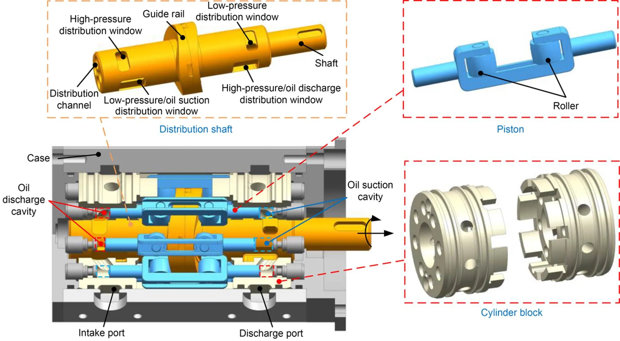
Fig. 1 Schematic diagram of the structure of the roller piston pump
The roller piston pump adopts a cam guide-roller type rolling support to replace the sliding pair support of the swash plate-slipper pair to realize the oil suction and discharge of the piston cavity. In addition, the shaft distribution is used to replace the original valve plate distribution and the driving shaft is used as the distribution shaft. This greatly simplifies the design of the axial piston pump. Such a configuration greatly reduces the number of sliding friction pairs of the axial piston pump, so as to avoid the influence of the sliding friction pair on the piston pump under high-speed and variable-speed conditions. Furthermore, the pump has a symmetrical design in structure, and the two pistons with a difference of 90° in the installation phase always keep the reverse reciprocating motion under the constraint of the guide rail, so as to achieve balance of the axial inertial force. Similarly, the flow phases corresponding to the two pistons that differ by 45° in the circumferential direction are also different by 45° to eliminate structural flow pulsation.
Fig. 2 illustrates the working principle of the roller piston pump in detail. The red marked area represents high pressure oil, and the blue marked area represents low pressure oil. During the working process, the motor rotates the distribution shaft and the pistons perform linear reciprocating motion under the constraint of the cylinder block and the guide rail. Then, the volume of the closed cavity changes periodically, so as to achieve the suction and discharge of oil. Taking piston A as an example, the changing law of oil suction and discharge and the communication change law of the distribution window when the left and right cavities are at different rotational angles are shown in Fig. 2.
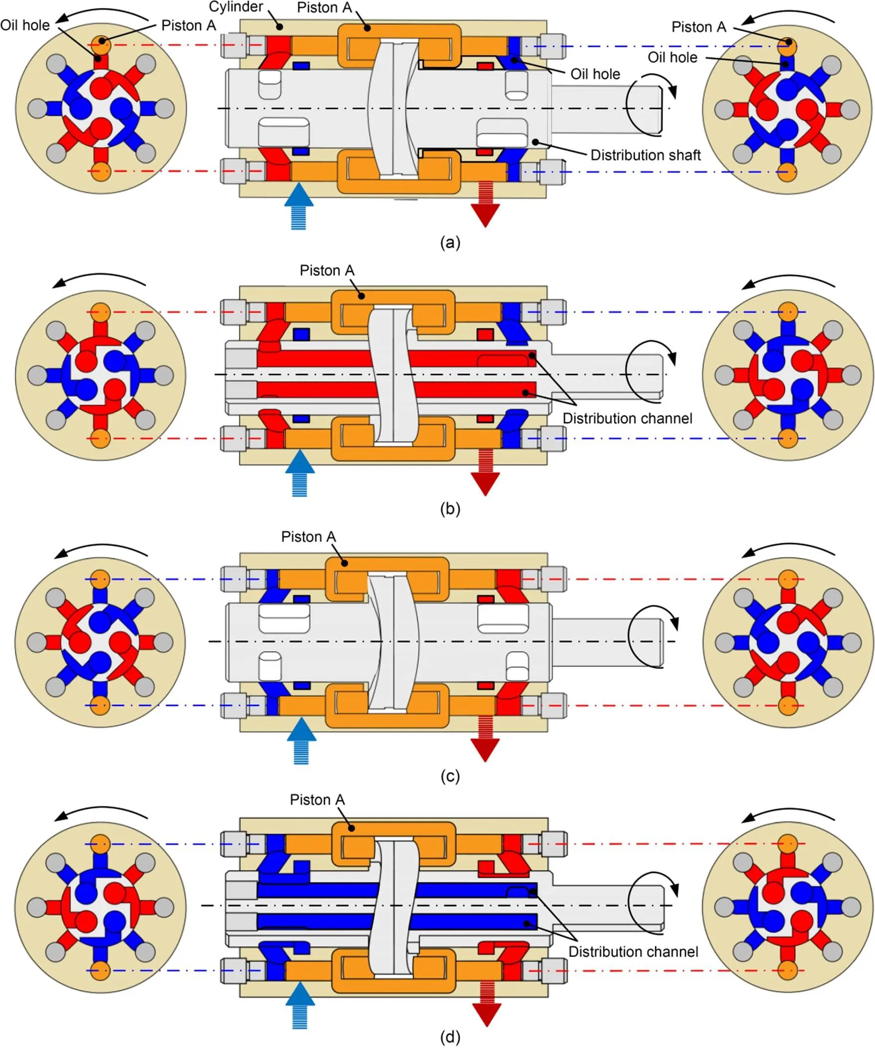
Fig. 2 Working principle of the roller piston pump with rotational angles: (a) 0°; (b) 45°; (c) 90°; (d) 135°. References to color refer to the online version of this figure
Taking Fig. 2a as the initial position, the rotational angle of the roller pump is 0° at this time, and piston A is at the far right end of the stroke. At that time, the volume of the left cavity is the largest, and the volume of the right cavity is the smallest. The oil holes corresponding to the left and right cavities do not communicate with the distribution window at all. During the evolution from Fig. 2a to Fig. 2b, the distribution shaft rotates from 0° to 45°, and the piston moves straight to the left axis with constant acceleration. The oil holes corresponding to the left and right cavities of the piston start to communicate with the distribution window respectively until they are completely communicated. The left cavity begins to discharge oil, and its volume begins to decrease. The right cavity begins to suck oil, and its volume begins to increase. When the distribution shaft rotates to 45°, the volumes of the left and right cavities of the piston are equal, as shown in Fig. 2b. During the evolution from Fig. 2b to Fig. 2c, the distribution shaft rotates from 45° to 90°, and piston A moves straight to the left axis with constant deceleration. The oil holes corresponding to the left and right cavities of the piston and the distribution window decrease gradually from complete communication to non-communication. The left cavity continues to discharge oil, and its volume continues to decrease. The right cavity continues to suck oil, and its volume continues to increase. When the distribution shaft rotates to 90°, as shown in Fig. 2c, the oil hole corresponding to the piston is completely disconnected from the distribution window, and the volume of the left cavity of the pump reaches the minimum and the volume of the right cavity reaches the maximum. During the evolution from Fig. 2c to Fig. 2d, the distribution shaft rotates from 90° to 135°, and piston A moves straight to the right with constant acceleration. The oil holes corresponding to the left and right cavities of piston A begin to communicate with the distribution window until they are completely communicated. The left cavity begins to suck oil, and its volume begins to increase. The right cavity begins to discharge oil and its volume begins to decrease. When the distribution shaft rotates to 135°, as shown in Fig. 2d, the volumes of the left and right cavities of the piston are equal. When the distribution shaft rotates from 135° to 180°, the piston moves straight to the right with constant deceleration. Its left cavity continues to suck oil, and its right cavity continues to discharge oil. When the distribution shaft rotates to 180°, it is consistent with the 0° state, as shown in Fig. 2a. At this time, the left cavity of the piston has completed absorbing oil and is about to start discharging oil, while the right cavity has completed discharging oil and is about to start sucking oil. During the rotation from 0° to 180°, a single piston completes two complete phases of oil suction and discharge. Therefore, when the distribution shaft rotates one cycle, a single piston completes four phases of oil suction and discharge, and the roller piston pump completes 32 phases of oil suction and discharge.
3 Mathematical model
3.1 Mechanical efficiency
Motion of the pistons in the roller piston pump is the main source of mechanical loss. It is known that the motion law of the two pistons whose installation phases differ by 45° also differs by 45°, so it is only necessary to analyze the force law of piston A through one cycle. Taking piston A at the rightmost position as the initial position of 0°, the volume of its left cavity is the largest and the volume of its right cavity is the smallest at this time.
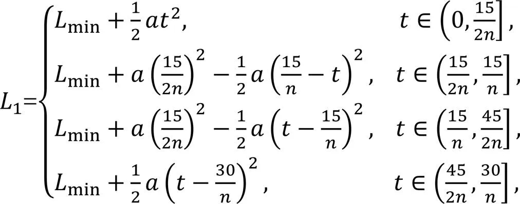
First, the motion law of piston A can be expressed by Eqs. (1)–(3):
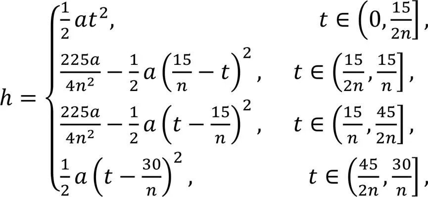
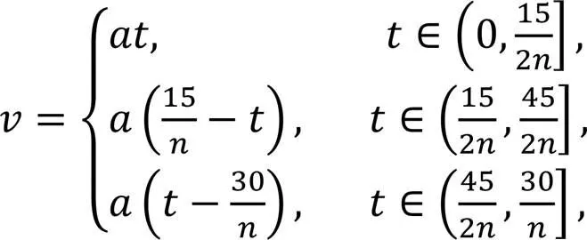
whereis the displacement of piston A,is the speed of its axial movement,is the time to rotate a certain angle from 0°,is the rotational speed of the guide rail, andis its acceleration of the axial movement.
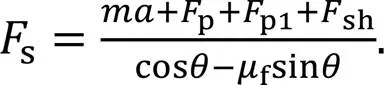
As the distribution shaft rotates from 0° to 45°, piston A moves straight to the left with constant acceleration. The force analysis is shown in Fig. 3.pis the thrust of the high-pressure cavity to piston A;sh1andsh2are the oil shearing forces between the piston and the cylinder block;p1is the resistance when it moves axially;sandfare the support force and friction force of the guide rail, respectively;sxandfxare the support force and friction force of the guide rail on the axial direction of the piston, respectively;is the pressure angle of the movement between the cylindrical roller and the guide rail.
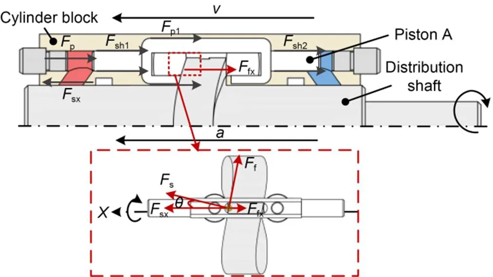
Fig. 3 Schematic diagram of the force of piston A when rotation is from 0° to 45°
Based on Newton's second law, the force balanced equation can be expressed as

whereis the mass of the piston.
The thrustpof the high-pressure cavity to piston A, the resultant oil shearing forceshbetween the piston and the cylinder block, and the resistancep1of its axial movement can be expressed as

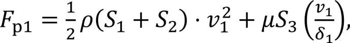
whereLis the instantaneous pressure in the left cavity of the piston,1is the axial movement speed of the piston A,is the cross-sectional area of the left piston rod, andis the dynamic viscosity of the oil.is the diameter of the piston rod,1is the contact length of the left piston rod and the cylinder block, and2is the contact length of the right piston rod and the cylinder block.is the width of clearance,is the oil density,1is the clearance between the side of the piston and the distribution shaft,1is the cross-sectional area of the piston on the left side of the guide rail, and2is the cross-sectional area of the piston on the right side of the guide rail. Further,3is the contact area between the side surface of the piston and the cylinder block. The callouts have been represented in Fig. 4.
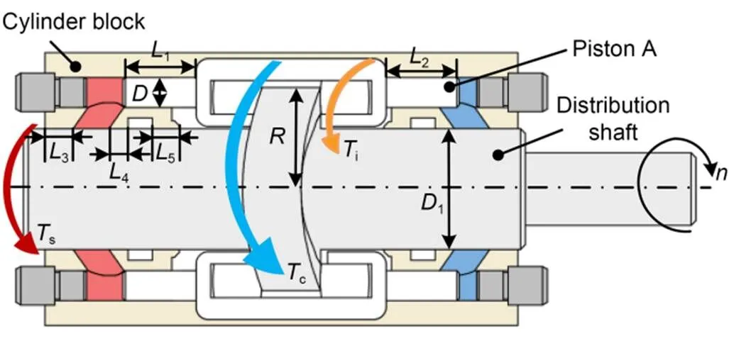
Fig. 4 Torque diagram of roller piston pump
To obtain the force of the guide rail to piston A, the contact between the guide rail and piston A is analyzed. As shown in Fig. 3, the piston is subjected to a supporting forcesperpendicular to the contact line between the cylindrical roller and the guide rail, andsxis the supporting force in the axial direction. Due to the existence of rolling friction, the cylindrical roller is also subjected to a friction forcefalong the tangential direction, andfxis the component force in the axial direction.sxandfxcan be represented by:
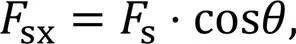
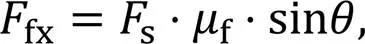
wherefis the coefficient of rolling friction, and the pressure anglecan be expressed by:
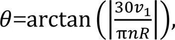
whereis the radius of the guide rail.
According to the above equations,scan be obtained as
Therefore, when the guide rail rotates from 0° to 45°, the torque of the guide rail to piston A can be expressed as

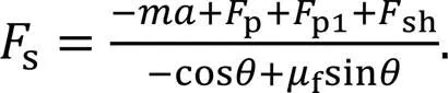
When the guide rail rotates from 45° to 90°, the combined force ofp,p1, andshdecelerates piston A. The force analysis of piston A is consistent with that when the guide rail rotates from 0° to 45°, and the difference is that the acceleration at Eq. (1) becomes a negative value, which means that the acceleration direction is to the right. However, when the pressure in the left cavity is too low, the hydraulic pressure and viscous resistance are not enough to force the piston to decelerate at a constant acceleration. The force balance equation andsat this time can be expressed as

When the distribution shaft rotates at 90°–135°, the force of the guide rail on piston A is the same as that with the rotation of 0°–45°, but the movement direction and acceleration direction are opposite to those with the rotation of 0°–45°. Similarly, when the guide rail rotates from 90° to 135°, the force of the piston can also be expressed by Eq. (9).
It is known thatiis expressed as the torque of the guide rail to the piston A. In addition, due to the rotational movement of the distribution shaft and the guide rail, the roller piston pump is also affected by two resistance moments during operation, as shown in Fig. 4. One is the shear resistance torquescaused by the gap between the distribution shaft and the cylinder block, and the other is the churning loss torqueccaused by the rotation of the guide rail group in the closed cavity.
scan be represented as

where3,4, and5are the contact lengths between the cylinder block and distribution shaft at various positions, and1is the diameter of the distribution shaft, as shown in Fig. 4.
Another drag torque is the churning loss torque due to the rotation of the cam guide. The churning loss torquecof the cam guide rail at different speeds is obtained through computational fluid dynamics (CFD) numerical simulation (Huang et al., 2020a), as shown in Fig. 5. Then, the mathematical model ofccan be obtained by fitting, and is expressed by

Finally, these torques are added to obtain the input torquefrom 0° to 90° for the roller piston pump to rotate:
wherei2is the input torque for piston A to rotate from 45° to 90°.
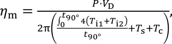
where90°is the amount of time needed for the moving parts to rotate from 0° to 90°,is the load pressure, andDis the pump's displacement.
3.2 Volumetric efficiency
Volumetric efficiency is a crucial characteristic index to use when assessing the roller piston pump's power density. Consistent with the mechanical efficiency analysis, the volumetric efficiency is modeled using the left cavity of piston A as an example. The initial position is when the volume of the left cavity is the largest. At that time, the left cavity of the piston finishes oil suction and is ready to start oil discharge. Based on the oil's compressibility, the instantaneous pressure changes in the left cavity of piston A can be expressed as:
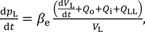
whereeis the elastic modulus of the oil,ois the left cavity's output flow,iis its input flow,LLis the leakage from the left cavity, andLis the left cavity's immediate volume.
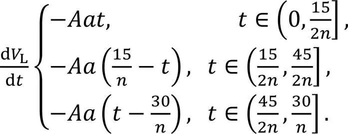
Piston A's location determines the immediate volume of the left cavity, and its movement speed is expressed as Eq. (2). It moves axially to the left and experiences constant acceleration as the guide rail rotates from 0° to 45°; its acceleration is shown in Eq. (3). As a result,Lcan be expressed as
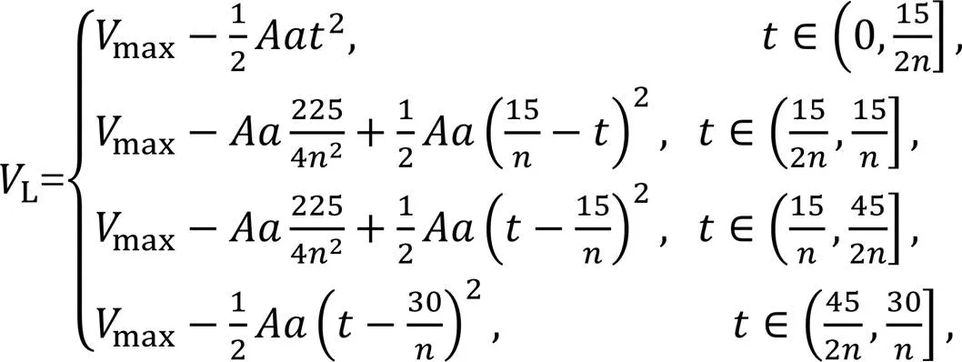
wheremaxis the maximum volume of the left cavity.
Taking the derivation of Eq. (20), we get:
The inlet flow and outlet flow of the left cavity of piston A can be expressed as:
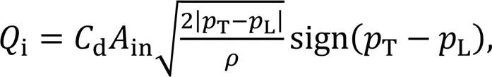
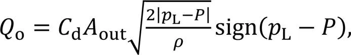
wheredis the flow coefficient,inandoutare the communication areas between the distribution cylinder and the suction and discharge ports, respectively, andTis the tank pressure.
According to the roller piston pump's working principle, the oil suction communication areainand the oil discharge communication areaoutcan be expressed as
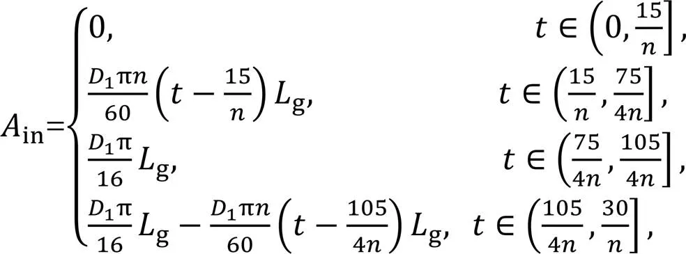
wheregis the width of the oil suction and discharge window on the discharge shaft.
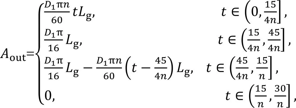
As shown in Fig. 6, the leakageLmainly includes external leakageLoand internal leakageLiin the roller piston pump. The external leakageLoincludes the outward leakageLo1of the high-pressure cavity oil through the gap between the piston rod's outer wall and the cylinder block's inner wall, and the outward leakageLo2from the clearance between the outer wall of the cylinder block and the outer wall of the distribution shaft. The internal leakageLiincludes the axial internal leakageLi1produced by the clearance between the outer wall of the distribution shaft and the inner wall of the cylinder block, and the circumferential internal leakageLi2caused by the clearance between the distribution shaft's outer wall and the cylinder block's inner wall.
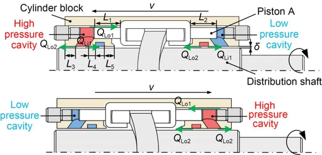
Fig. 6 Schematic diagram of leakage with rotations of: (a) 0°–90°; (b) 90°–180°
The flow due to the existence of pressure difference is called Poiseuille flow, the flow due to the existence of relative motion is called Couette flow, and the superposition of the two is called Couette-Poiseuille flow.Lo1is caused by Couette-Poiseuille flow, andLo2is caused by Poiseuille flow. Therefore,Lo1andLo2can be expressed as
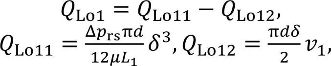
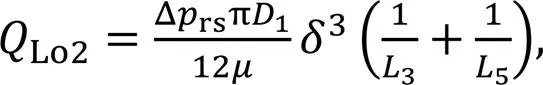
where Δrsis the difference in pressure between the high-pressure cavity and the ambient pressure, andis the diameter of the piston rod. As shown in Fig. 6,1is the contact length between the piston rod and the left cylinder block,3is the contact length between the distribution shaft and the outermost end of the left cylinder block, and5is the contact length between the distribution shaft and the innermost end of the right cylinder block.
1can be expressed as
whereminis the shortest distance between the piston rod and the left cylinder block.
Li1can be expressed as
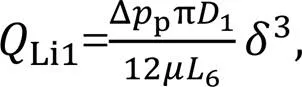
where Δpis the difference in pressure between the low-pressure annular flow channel and the high-pressure cavity of the piston, and6is the distance between the high-pressure cavity and the low-pressure annular flow channel.
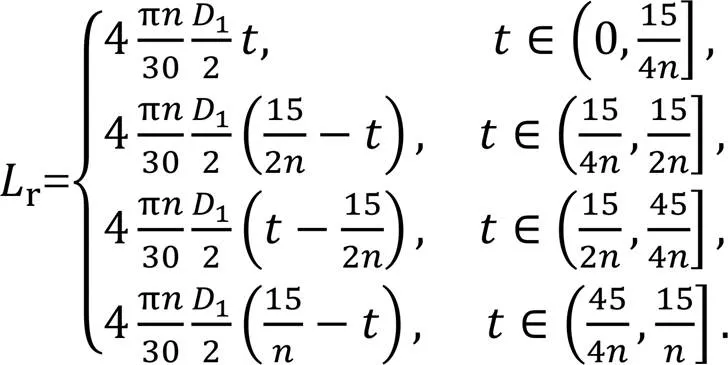
As shown in Fig. 7, when the distribution shaft is rotating, there is a circumferential internal leakageLi2between the inner wall of the cylinder block and the outer wall of the distribution shaft. The red mark in the figure represents high-pressure oil, and the blue mark represents low-pressure oil. The contact lengthrbetween the distribution shaft and the cylinder block changes as the rotational angle changes, which can be expressed as
The total leakageLTcan be expressed as


4 Simulation results and discussion
Based on the theoretical models listed above, the effects of rotational speed and load pressure on the mechanical efficiency and volumetric efficiency of the pump were studied, respectively. The simulation parameter settings are detailed in Table S1 of the electronic supplementary materials (ESM).
4.1 Mechanical efficiency
To analyze the input torque of the pump, the installation phases of 0°, 90°, 180°, and 270° pistons are combined into one group, which is recorded as group I. The installation phases of 45°, 135°, 225°, and 315° pistons are combined into another group, which is recorded as group II. Then superimposing the input torque of group I pistons and group II pistons, each time when the roller piston pump rotates to 45°, there will be a sudden change in torque, as shown in Fig. 8. The magnitude of the sudden change in torque increases with the increase of rotational speed. However, the sudden value of torque does not change with the change of load pressure.
Fig. 8 Input torque T of roller piston pump at different speeds and load pressures: (a) different rotational speeds when the load pressure is 8 MPa; (b) different load pressures when the rotational speed is 8000 r/min

Fig. 9 Simulation results of mechanical efficiency at different speeds and load pressures
4.2 Volumetric efficiency

Fig. 11 shows the flow curves of piston A at different rotational speeds and load pressures. It can be seen in Fig. 11a that when the load pressure is 8 MPa, the output flow increases linearly with the increase in rotational speed, and the peak value of the backflow increases with the increase in rotational speed. Due to the difference in rotational speed, the angular range of the backflow increases with the increase of rotational speed, but it is not obvious. Backflow occurs when the working cavity just communicates with the oil discharge port. At that moment, the pressure outside the cavity is consistent with the load pressure, and the pressure inside the cavity is less than the outside pressure. The instantaneous pressure difference causes the oil to flow into the working cavity, thereby helping the working cavity to build up pressure. Then the working cavity reduces the volume of the cavity and increases the pressure in the cavity, so that the oil is discharged from the cavity to the outside of the cavity. When the rotational speed is constant, the instantaneous pressure difference between the inside and outside of the oil discharge cavity increases as the load pressure increases. At that time, the backflow of the oil discharge working cavity also increases, as shown in Fig. 11b. Also, there is a small abrupt change at 0°, 45°, 90°, and 135°, which is caused byLi2from the pump. Detailed analysis of the leakage is in the ESM.
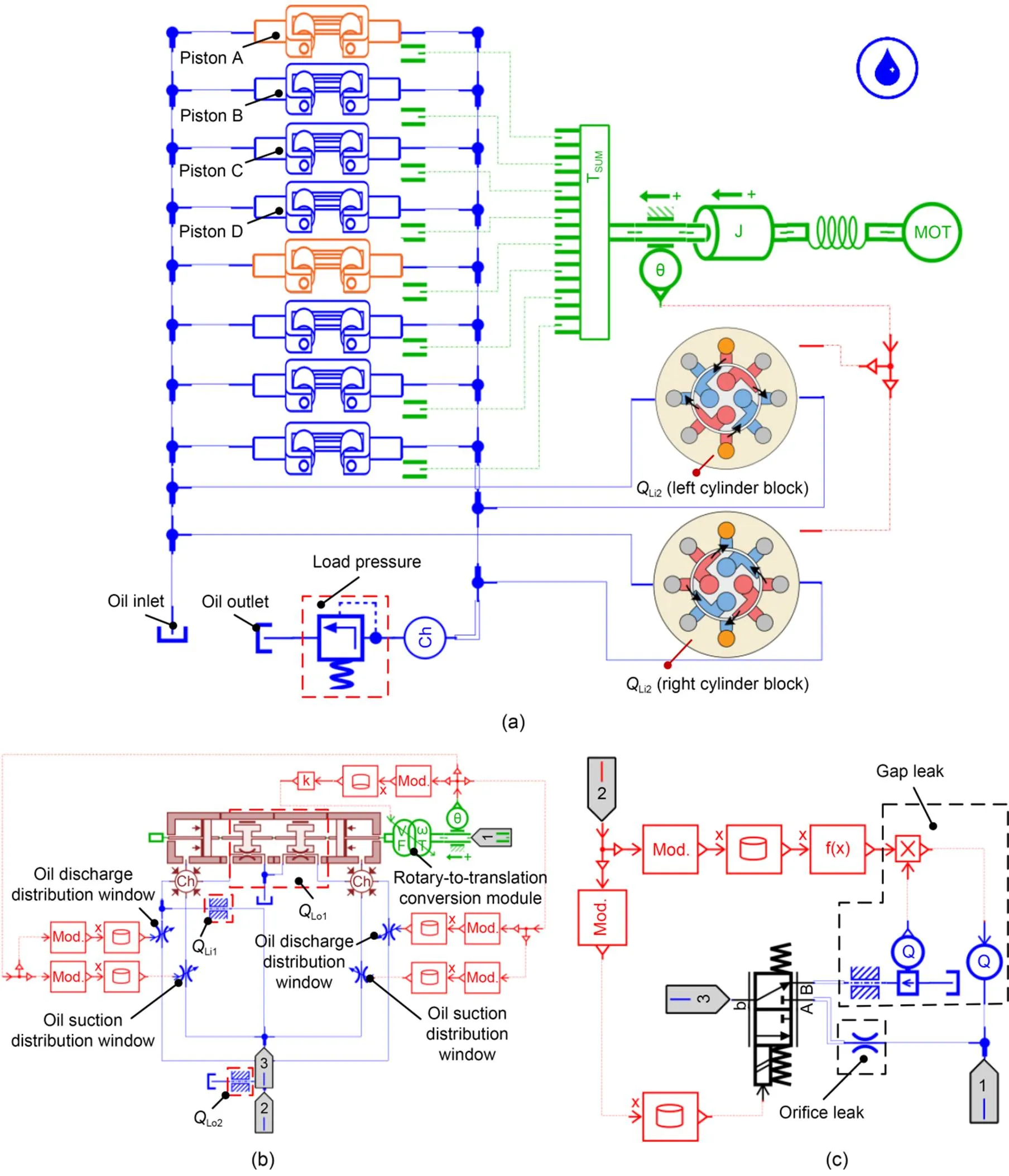
Fig. 10 AMESim models of roller piston pump: (a) hydraulic system model; (b) sub-model of piston A; (c) sub-model of QLi2
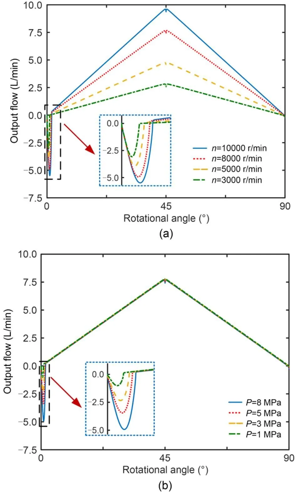
Fig. 11 Output flow of roller piston pump at different speeds and load pressures: (a) different rotational speeds when load pressure is 8 MPa; (b) different load pressures when rotational speed is 8000 r/min
The impact of rotational speed and load pressure on the roller piston pump's volumetric efficiency is depicted in Fig. 12. Different symbols represent different rotational speeds. When the rotational speed is constant, the volumetric efficiency decreases with the increase of load pressure due to the increase of backflow and leakage. When the load pressure remains constant, the required amount of backflow is constant, and the volumetric efficiency rises as the rotational speed increases.
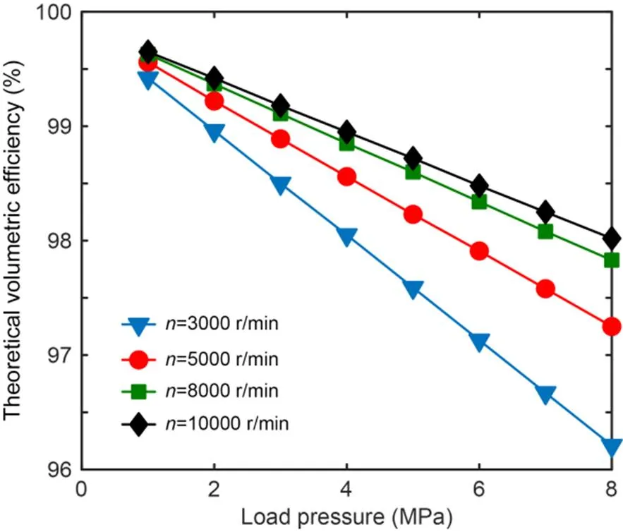
Fig. 12 Simulation results of volumetric efficiency at different speeds and load pressures
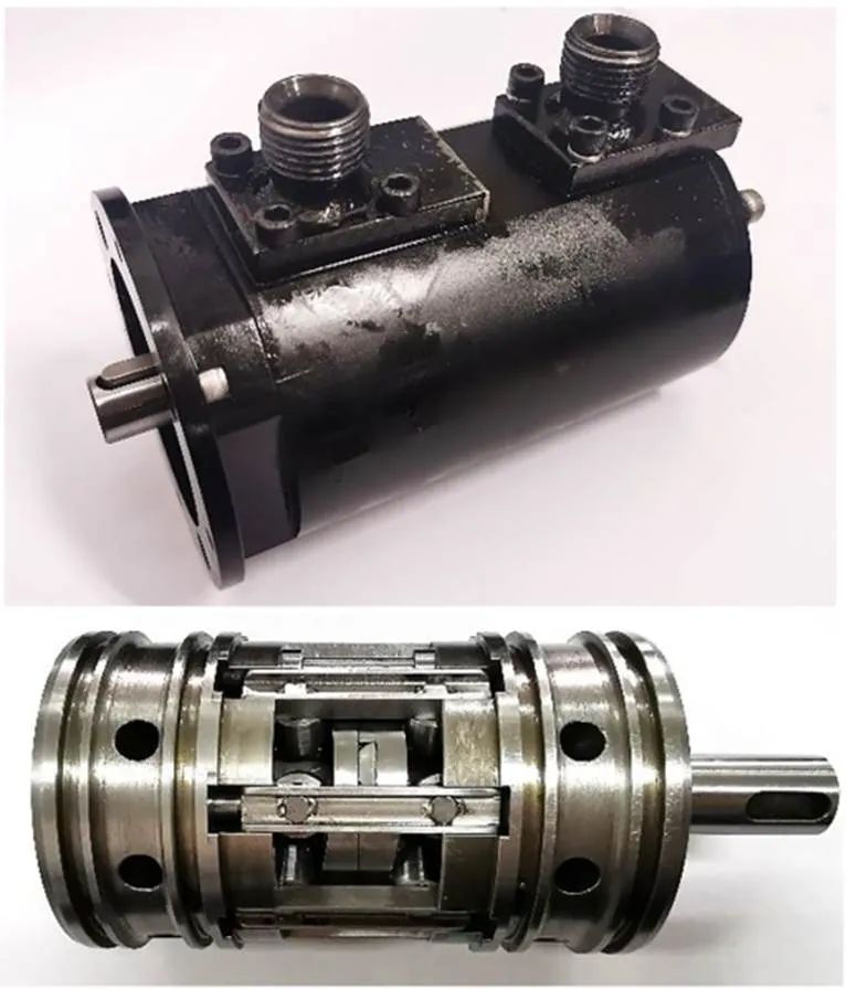
Fig. 13 Prototype of the roller piston pump
5 Experimental study
In order to verify that the roller piston pump has high mechanical efficiency and volumetric efficiency, the principle prototype of the roller piston pump is fabricated, as shown in Fig. 13, and its structural parameters are shown in Table 1.
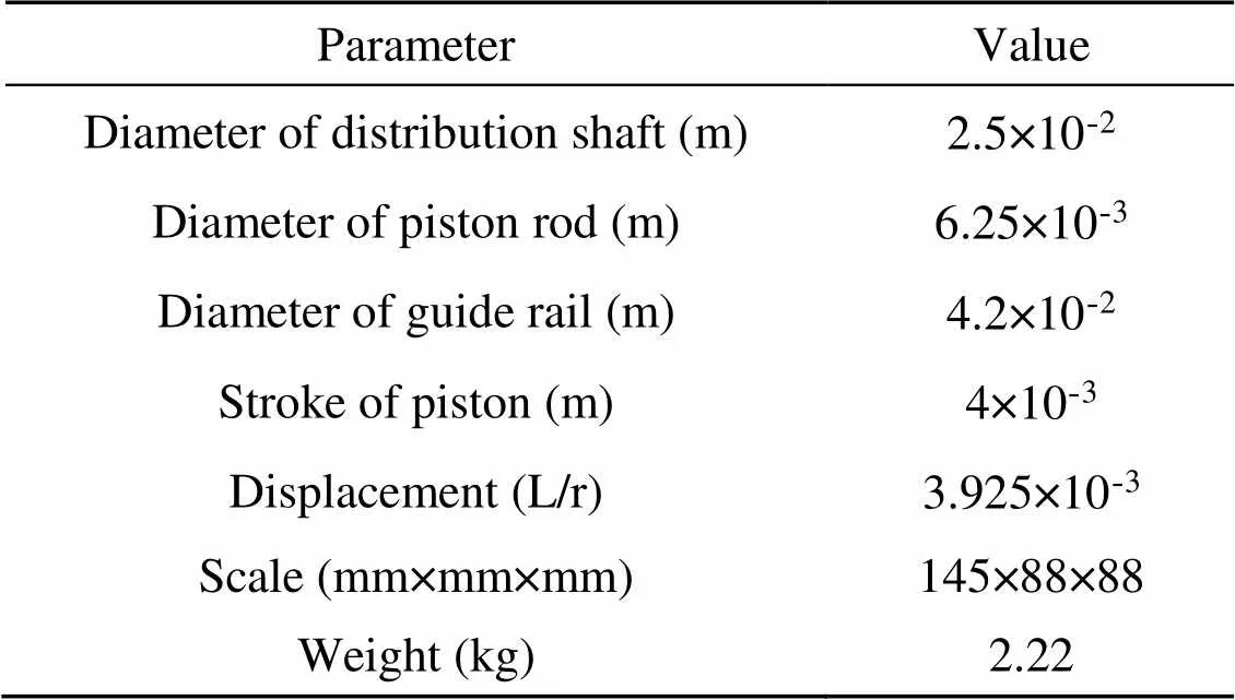
Table 1 Crucial structural parameters of the prototype pump
Fig. 14a is a schematic diagram of the experimental system. A special test bench was built to test the outlet pressure, outlet flow, and instantaneous torque of the prototype pump at various rotational speeds and load pressures, as shown in Fig. 14b. A torque-speed sensor was installed between the prototype pump and the driving motor to measure the input torque and input speed of the motor. To ensure sufficient oil absorption of the prototype pump, an oil supply pump was provided. In addition, pressure sensors were installed at the prototype pump's inlet and outlet to obtain the oil pressure at the inlet and outlet. Adjustment of the pressure was realized through the relief valve, and a flow meter was also installed downstream of the relief valve to monitor the output flow of the prototype pump. Finally, the data obtained by the test was displayed on the computer through the data acquisition device.
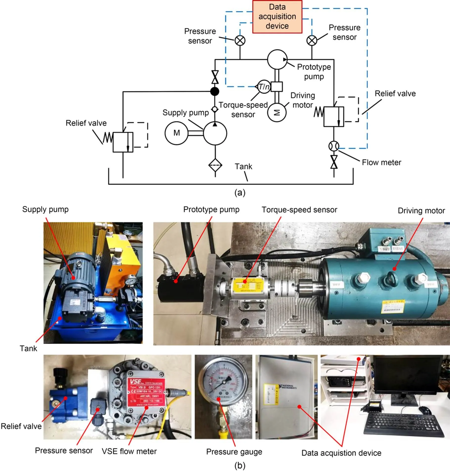
Fig. 14 Schematic and physical diagrams of the test bench: (a) system schematic of the test bench; (b) overall physical diagrams of the test bench
To obtain the mechanical efficiency and volumetric efficiency of the roller piston pump, the outlet pressure of the roller piston pump, the flow rate, and the instantaneous torque under different load pressures and speeds were measured by the test bench, as shown in Fig. 15. First, Fig. 15a shows the load pressure applied on the roller piston pump measured by the pressure sensor, Fig. 15b is the outlet flow of the roller piston pump at different load pressures and speeds, and Fig. 15c represents the torque of the roller piston pump during the process of adding load pressure measured by the torque sensor. Due to the accuracy of the pressure sensor and torque sensor, there are small fluctuations in the experimental data in Figs. 15a and 15c but it is reasonable to take the average torque within the same rotation time.
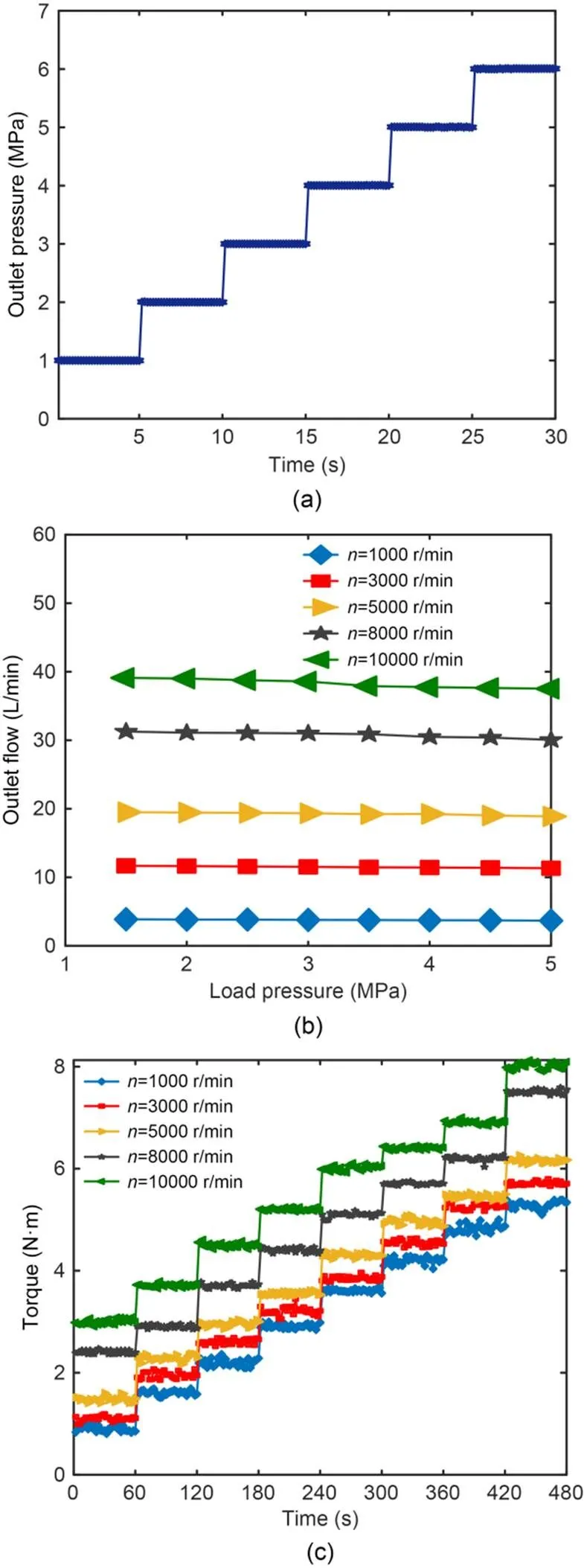
Fig. 15 Experimental data: (a) outlet pressure; (b) outlet flow; (c) instantaneous torque
The experimental results of the mechanical efficiency of the roller piston pump are shown in Fig. 16. The outcomes of the mathematical model agree with the experimental results of the prototype pump. As shown in Figs. 16a and 16b, when the rotational speed is constant, the mechanical efficiency rises with the increase of the load pressure. However, as shown in Figs. 16c and 16d, when the load pressure is constant, the mechanical efficiency decreases as the rotational speed increases. In addition, due to the machining accuracy of the roller piston pump and the stiffness of the material, the difference between the simulation results and the experimental results is around 10%, and the difference rises with the increase of speed and load pressure. When the load pressure is 8 MPa and the speed is 3000 r/min, the mechanical efficiency is 91.7%, and when the speed rises to 10000 r/min, the mechanical efficiency can still be maintained at 66.7%. Compared with the traditional axial piston pump, the experimental data of the roller piston pump confirms its good mechanical efficiency in wide-speed and high-speed conditions.
In addition, when the load pressure is constant, it can be found that the difference between the simulation results and the experimental results increases with the increase of the rotational speed. When the rotational speed increases above 8000 r/min, the difference exceeds 10%. This may be because that as the speed increases, the cylindrical roller rotates too fast, which causes it not to roll normally. To verify that conjecture, the simulation results under different friction coefficients are compared with the experimental results, as shown in Fig. 17. When the friction coefficient increases, the simulation results of the mechanical efficiency clearly decrease, and there is an intersection with the experimental results. It can be inferred that when the speed of the pump exceeds 9000 r/min, the coefficient of friction is already as high as 0.04. It is known that the diameter ratio of the guide rail to the cylindrical roller is 6׃1, and the rotational speed of the cylindrical roller is as high as 54000 r/min. Such experimental results also provide guidance and reference significance for subsequent research on the transmission part of the roller pump. For example, the selection of larger-sized rollers can effectively reduce the self-propagation speed.
The experimental results of the roller piston pump's volumetric efficiency at various speeds and load pressures are shown in Fig. 18. The volumetric efficiencies of the prototype pump's experimental results and simulation results are largely in agreement. Experiments show that the roller piston pump has high volumetric efficiency. When the speed is 10000 r/min and the load pressure is 8 MPa, its volumetric efficiency is as high as 95.59%. As shown in Figs. 18a and 18b, with the increase of load pressure, both backflow and leakage increase as the load pressure increases. Thus, the experimental results of volumetric efficiency decrease with the increasing load pressure. As shown in Figs. 18c and 18d, when the load pressure is constant, the leakage amount decreases as the rotational speed increases because the backflow does not change. Consequently, as the rotational speed increases, the experimental results of volumetric efficiency rise. Under wide-speed and high-speed conditions, the experimental results show that the novel roller piston pump has extremely high volumetric efficiency and low leakage, which confirms the good feasibility of the novel structure. The experimental results are generally consistent with the simulation results at low speed and load pressure, and the maximum error value is 2.43%.
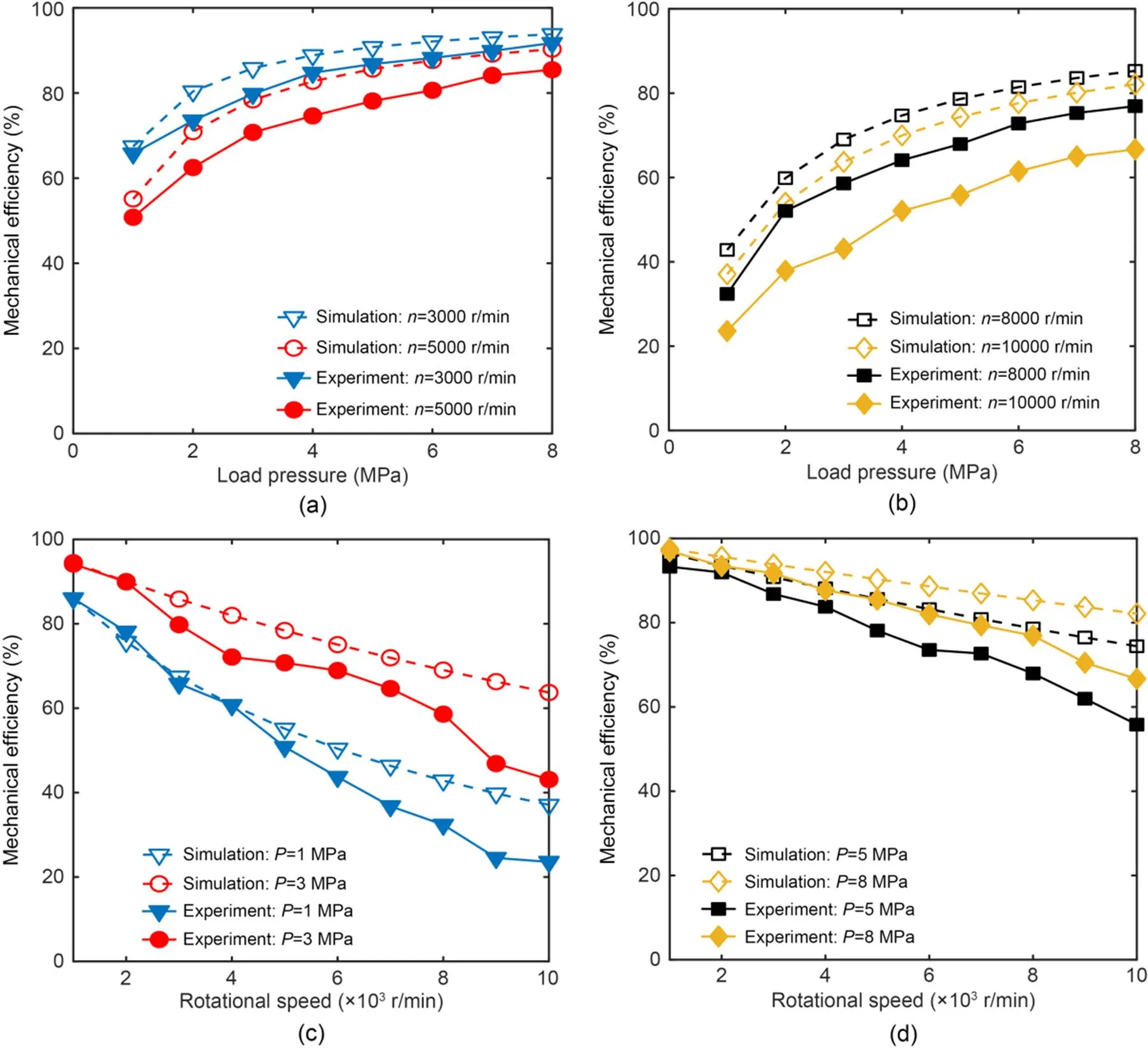
Fig. 16 Simulation and experimental results of mechanical efficiency: (a) rotational speeds of 3000 and 5000 r/min; (b) rotational speeds of 8000 and 10000 r/min; (c) load pressures of 1 and 3 MPa; (d) load pressures of 5 and 8 MPa
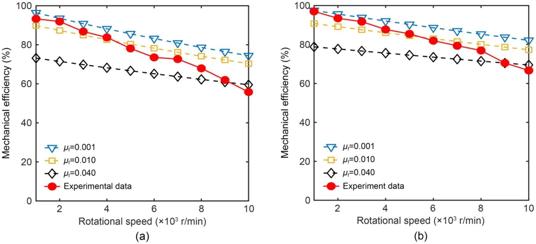
Fig. 17 Simulation and experimental results at different friction coefficients: (a) load pressure of 5 MPa; (b) load pressure of 8 MPa
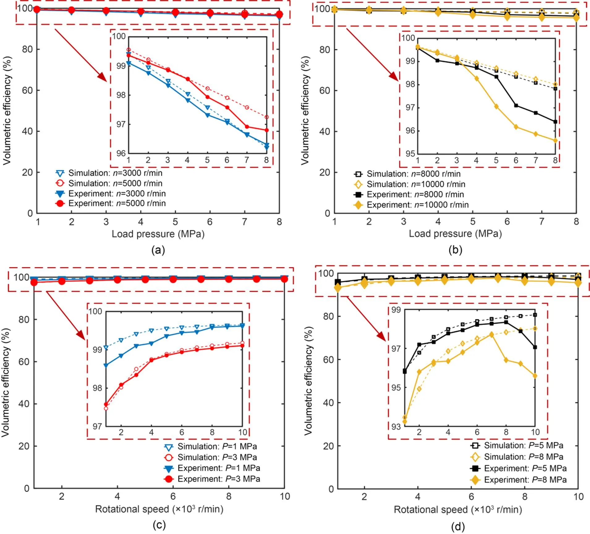
Fig. 18 Simulation results and experimental results of volumetric efficiency: (a) rotational speeds of 3000 and 5000 r/min; (b) rotational speeds of 8000 and 10000 r/min; (c) load pressures of 1 and 3 MPa; (d) load pressures of 5 and 8 MPa
However, as shown in Fig. 18d, when the speed exceeds 7000 r/min, the volumetric efficiency decreases with the increasing speed. This may be because the temperature of the oil rises rapidly under high-speed and high-load conditions and the viscosity decreases, resulting in increased leakage. To verify this conjecture, the simulation results under different oil viscosities are compared with the experimental results, as shown in Fig. 19. When the oil viscosity increases, the simulation results of the volumetric efficiency clearly increase and have an intersection with the experimental results. It can be estimated that the oil viscosity is 0.005 when the load pressure is 8 MPa and the speed is 10000 r/min.
Finally, the performance of the roller piston pump is compared with the traditional axial piston pump (Chao, 2019) and the traditional 2D piston pump (Huang et al., 2020b, 2020c) preliminarily, as shown in Table 2. Since the structural parameters of these three pumps are different, the comparison of displacement is of little significance. Compared with the traditional axial piston pump, the maximum speed of both can reach 10000 r/min. However, at the highest efficiency point, the volumetric efficiency and mechanical efficiency of the roller piston pump are 96.4% and 88.4%, respectively, which are both higher than those of the traditional axial piston pump. Compared with the traditional 2D piston pump, the maximum speed of the roller piston pump is twice that of the original. In addition, the volumetric efficiency and mechanical efficiency are greatly improved. Therefore, the high efficiency advantage of the roller piston pump has also been initially verified.
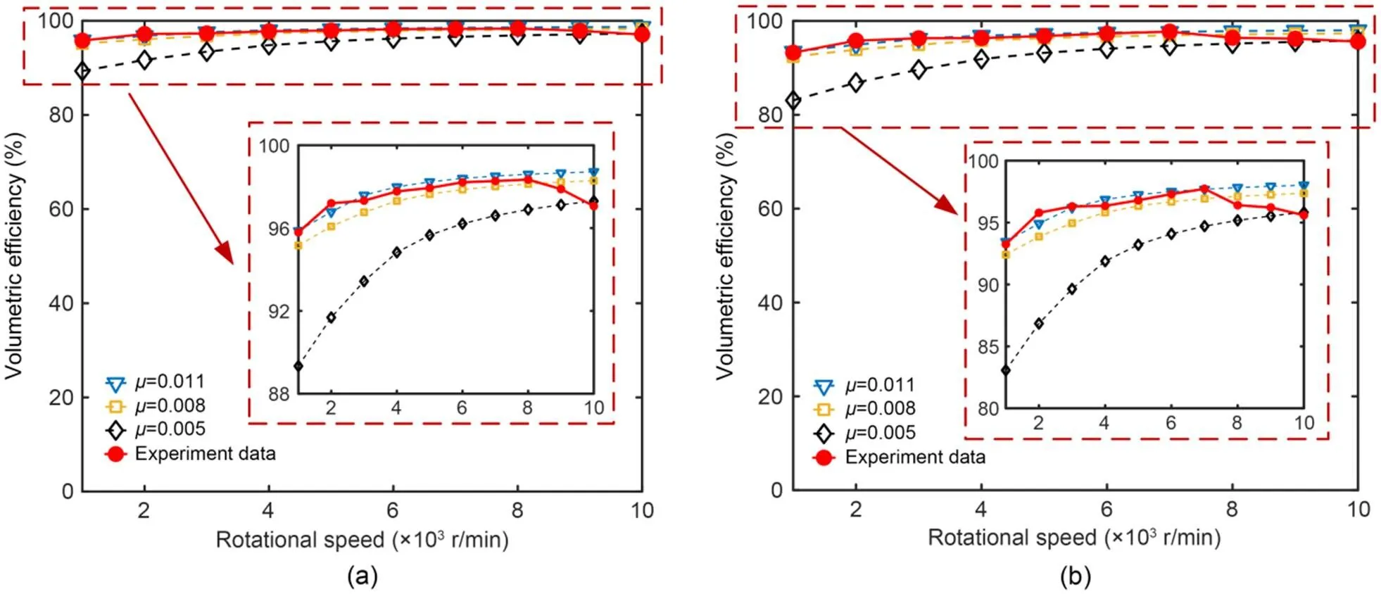
Fig. 19 Simulation and experimental results at different oil viscosities: (a) load pressure of 5 MPa; (b) load pressure of 8 MPa
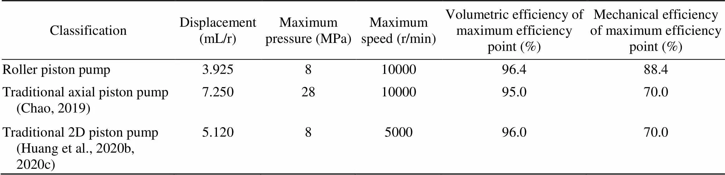
Table 2 Comparisons between roller piston pump and traditional axial piston pump and 2D piston pump
6 Conclusions
1. A novel roller piston pump is presented where a cam guide-roller type rolling support is adopted to replace the sliding pair support of the swash plate-slipper pair to achieve the piston cavity's oil suction and discharge. In addition, the shaft distribution is used to replace the original valve plate distribution, and the driving shaft is used as the distribution shaft, which greatly simplifies the axial piston pump's design. Through the symmetrical design of the structure, the inertial force balance of the pump and the realization of no structural flow pulsation are achieved and meet the requirements of high integration and small pressure pulsation for aviation hydraulic pumps.
2. Based on the motion law and distribution principle of the roller piston pump, the mathematical models of the pump's mechanical efficiency and volumetric efficiency are respectively established. Through the numerical simulation of MATLAB and AMESim, the influence of rotational speed and load pressure on the mechanical efficiency and volumetric efficiency of the piston pump is analyzed. Moreover, it is proved that there is no structural flow pulsation in the roller pump. When the load pressure of the roller piston pump is constant, the mechanical efficiency decreases with the increase of the rotational speed, and the volumetric efficiency increases with the increase of the rotational speed. When the rotational speed remains constant, the mechanical efficiency increases with the increasing load pressure, while the volumetric efficiency decreases.
3. The experimental results demonstrate the excellent efficiency of the roller piston pump. When the load pressure is 8 MPa and the rotation speed is increased from 3000 to 10000 r/min, the mechanical efficiency changes from high to low, and the range is 91.7%–66.7%, and the volumetric efficiency changes from low to high, and the range is 95.6%–97.8%. In addition, when the load pressure is 1–8 MPa and the rotational speed is 3000–10000 r/min, the volumetric efficiency of the roller pump varies from 95.6% to 99.6%. The results show that the removal of the valve plate through structural innovation reduces leakage and greatly improves volumetric efficiency. The roller pump can rotate at a maximum speed of 10000 r/min or higher, which meets the needs of high speed and variable speed for aerospace fuel pumps.
Acknowledgments
This work is supported by the National Key Research and Development Program of China (No. 2019YFB2005202).
Author contributions
Jian RUAN designed the research. Chenchen ZHANG, Yiren ZANG, and Heyuan WANG processed the corresponding data. Chenchen ZHANG wrote the first draft of the manuscript. Sheng LI helped to organize the manuscript. Bin MENG revised and edited the final version.
Conflict of interest
Chenchen ZHANG, Yiren ZANG, Heyuan WANG, Bin MENG, Sheng LI, and Jian RUAN declare that they have no conflict of interest.
Chao Q, 2019. Research on Some Key Technologies of High-Speed Rotation for Axial Piston Pumps Used in EHAs. PhD Thesis, Zhejiang University, Hangzhou, China (in Chinese).
Chao Q, Zhang JH, Xu B, et al., 2018. Multi-position measurement of oil film thickness within the slipper bearing in axial piston pumps., 122:66-72. https://doi.org/10.1016/j.measurement.2018.03.016
Chao Q, Zhang JH, Xu B, et al., 2019a. A review of high-speed electro-hydrostatic actuator pumps in aerospace applications: challenges and solutions., 141(5):050801. https://doi.org/10.1115/1.4041582
Chao Q, Zhang JH, Xu B, et al., 2019b. Test rigs and experimental studies of the slipper bearing in axial piston pumps: a review., 132:135-149. https://doi.org/10.1016/j.measurement.2018.09.027
Chao Q, Zhang JH, Xu B, et al., 2022. Integrated slipper retainer mechanism to eliminate slipper wear in high-speed axial piston pumps., 17(1):1. https://doi.org/10.1007/s11465-021-0657-z
Chen Y, Zhang JH, Xu B, et al., 2019. Multi-objective optimization of micron-scale surface textures for the cylinder/valve plate interface in axial piston pumps., 138:316-329. https://doi.org/10.1016/j.triboint.2019.06.002
Guo SR, Chen JH, Lu YL, et al., 2020. Hydraulic piston pump in civil aircraft: current status, future directions and critical technologies., 33(1):16-30. https://doi.org/10.1016/j.cja.2019.01.013
Hooke CJ, Li KY, 1989. The lubrication of slippers in axial piston pumps and motors—the effect of tilting couples., 203(5):343-350. https://doi.org/10.1243/PIME_PROC_1989_203_123_02
Hu WN, Zhou L, Tian YS, et al., 2015. Analysis for the power loss of electro hydrostatic actuator and hydraulic actuator. Proceedings of the IEEE International Conference on Advanced Intelligent Mechatronics, p.613-616. https://doi.org/10.1109/AIM.2015.7222604
Huang HH, Jin R, Li L, et al., 2018. Improving the energy efficiency of a hydraulic press via variable-speed variable-displacement pump unit., 140(11):111006. https://doi.org/10.1115/1.4040325
Huang Y, Ding C, Wang HY, et al., 2020a. Numerical and experimental study on the churning losses of 2D high-speed piston pumps., 14(1):764-777. https://doi.org/10.1080/19942060.2020.1763468
Huang Y, Ruan J, Zhang CC, et al., 2020b. Research on the mechanical efficiency of high-speed 2D piston pumps., 8(7):853. https://doi.org/10.3390/pr8070853
Huang Y, Ruan J, Chen Y, et al., 2020c. Research on the volumetric efficiency of 2D piston pumps with a balanced force., 13(18):4796. https://doi.org/10.3390/en13184796
Ivantysynova M, Lasaar R, 2004. An investigation into micro- and macrogeometric design of piston/cylinder assembly of swash plate machines., 5(1):23-36. https://doi.org/10.1080/14399776.2004.10781181
Jiao XX, Jing B, Huang YF, et al., 2017. Research on fault diagnosis of airborne fuel pump based on EMD and probabilistic neural networks., 75:296-308. https://doi.org/10.1016/j.microrel.2017.03.007
Jin R, Huang HH, Li L, et al., 2019. Energy saving strategy of the variable-speed variable-displacement pump unit based on neural network., 80:84-88. https://doi.org/10.1016/j.procir.2019.01.108
Koc E, Hooke CJ, Li KY, 1992. Slipper balance in axial piston pumps and motors., 114(4):766-772. https://doi.org/10.1115/1.2920946
Li HQ, Zhang J, Yan JN, 2016. Effects of partial fuel pump failure on center of gravity control for high-speed aircraft. Proceedings of the IEEE International Conference on Aircraft Utility Systems, p.146-150. https://doi.org/10.1109/AUS.2016.7748037
Li MT, Foss R, Stelson KA, et al., 2019. Design, dynamic modeling, and experimental validation of a novel alternating flow variable displacement hydraulic pump., 24(3):1294-1305. https://doi.org/10.1109/TMECH.2019.2906859
Lu L, Xu YP, Li MR, et al., 2022. Analysis of fretting wear behavior of unloading valve of gasoline direct injection high-pressure pump., 23(4):314-328. https://doi.org/10.1631/jzus.A2100685
Manring ND, Mehta VS, Nelson BE, et al., 2014. Scaling the speed limitations for axial-piston swash-plate type hydrostatic machines., 136(3):031004. https://doi.org/10.1115/1.4026129
Pelosi M, Ivantysynova M, 2012. A geometric multigrid solver for the piston–cylinder interface of axial piston machines., 55(2):163-174. https://doi.org/10.1080/10402004.2011.639049
Rizzo G, Massarotti GP, Bonanno A, et al., 2015. Axial piston pumps slippers with nanocoated surfaces to reduce friction., 16(1):1-10. https://doi.org/10.1080/14399776.2015.1006979
Rizzo G, Bonanno A, Massarotti GP, et al., 2016. Energy efficiency improvement by the application of nanostructured coatings on axial piston pump slippers. Proceedings of the 10th International Fluid Power Conference, p.313-328.
Schuhler G, Jourani A, Bouvier S, et al., 2018. Efficacy of coatings and thermochemical treatments to improve wear resistance of axial piston pumps., 126:376-385. https://doi.org/10.1016/j.triboint.2018.05.007
Singh P, Sharma S, Sinha R, et al., 2015. Review of aircraft fuel system., 1(1):1120.
Tang HS, Yin YB, Ren Y, et al., 2018. Impact of the thermal effect on the load-carrying capacity of a slipper pair for an aviation axial-piston pump., 31(2):395-409. https://doi.org/10.1016/j.cja.2017.06.004
Wang B, Hao YX, Quan L, et al., 2020. Research on characteristics of electro-hydraulic servo system by sub-chamber independent variable-speed pumps control., 56(18):235-243 (in Chinese). https://doi.org/10.3901/JME.2020.18.235
Xia SQ, Zhang JH, Ye SG, et al., 2019. A spare support vector machine based fault detection strategy on key lubricating interfaces of axial piston pumps., 7:178177-178186. https://doi.org/10.1109/ACCESS.2019.2958141
Ye SG, Zhang JH, Xu B, 2018. Noise reduction of an axial piston pump by valve plate optimization., 31(1):57. https://doi.org/10.1186/s10033-018-0258-x
Ye SG, Zhang JH, Xu B, et al., 2021. A theoretical dynamic model to study the vibration response characteristics of an axial piston pump., 150:107237. https://doi.org/10.1016/j.ymssp.2020.107237
Zhang JH, Chao Q, Wang QN, et al., 2017. Experimental investigations of the slipper spin in an axial piston pump., 102:112-120. https://doi.org/10.1016/j.measurement.2017.01.035
Zhang JH, Chen Y, Xu B, et al., 2019. Effects of splined shaft bending rigidity on cylinder tilt behaviour for high-speed electro-hydrostatic actuator pumps., 32(2):499-512. https://doi.org/10.1016/j.cja.2018.03.007
Zhao JA, Fu YL, Ma JM, et al., 2021. Review of cylinder block/valve plate interface in axial piston pumps: theoretical models, experimental investigations, and optimal design., 34(1):111-134. https://doi.org/10.1016/j.cja.2020.09.030
Sections S1–S6, Tables S1–S3
https://doi.org/10.1631/jzus.A2200378
Revision accepted Dec. 4, 2022;
Crosschecked July 31, 2023
© Zhejiang University Press 2023
Aug. 9, 2022;
 Journal of Zhejiang University-Science A(Applied Physics & Engineering)2023年9期
- Journal of Zhejiang University-Science A(Applied Physics & Engineering)的其它文章
- Noise robustness of an operational modal-based structural damage-detection scheme using impact-synchronous modal analysis
- Bifurcation control of solid angle car-following model through a time-delay feedback method
- A data-driven approach for modeling and predicting the thrust force of a tunnel boring machine
- Molecular force mechanism of hydrodynamics in clay nanopores
- Finite-time path following control of a sailboat with actuator failure and unknown sideslip angle