
Bogie active stability simulation and scale rig test based on frame lateral vibration control
2023-07-24 10:07YadongSONGHuLIJunCHENGYuanYAO
Yadong SONG,Hu LI,Jun CHENG,Yuan YAO
State Key Laboratory of Traction Power, Southwest Jiaotong University, Chengdu 610031, China
Abstract: This paper puts forward a high-speed train bogie active stability method,based on frame lateral vibration control,for improving the stability and critical speed of railway vehicles at high speeds.Two inertial actuators apply active control forces to the front and rear end beams of the bogie frame.A scale model of bogie lateral dynamics is established,as well as the state space equation of the control system.Also,the multi-objective optimization is used to construct state feedback parameters,which take hunting stability and control effort into account.Furthermore,the effects of time-delay in the control system and suspension parameters on bogie hunting stability are studied.The dynamic behaviors and the stability mechanism of the bogie control system are analyzed.Finally,a 1:5 scale test rig is used to conduct a bogie active stability experiment.The results reveal that active control of frame lateral vibration can effectively improve the bogie system’s hunting stability margin at high speeds,but time-delay in the control system cannot be ignored.
Key words: Railway vehicle;Bogie;Active stability;Scale test rig;Time-delay
1 Introduction
With an increase in train speeds,the dynamic performance of the train,such as increased vibration and wheel-rail force,deteriorates (Jin,2014).Hunting stability is a crucial feature of railway vehicle system dynamic performance since it determines the highest operating speed of the train.The vehicle system must maintain stability throughout the range of normal op‐erating speeds or else an excessive hunting motion may occur,affecting the vehicle’s running performance and even causing damage or derailment.Vibration in‐duced by the track,particularly the lateral vibration of the vehicle,is unavoidable when the train is running.To solve the stability and comfort problems of highspeed trains in operation,active or semi-active control is useful (Goodall,1997;Pérez et al.,2002;Pearson et al.,2004;Braghin et al.,2006;Bruni et al.,2007;Alfi et al.,2011;Kim et al.,2017;Zeng et al.,2020;Sun et al.,2023).The scaled bogie test rig simulation and experimentation is an effective research technique(Hou et al.,2019;Shrestha et al.,2020).
The theory of active control has been put forward for several decades,and scholars have extensively studied the concept of active control on railway vehi‐cles (Fu et al.,2020).Unlike a passive suspension sys‐tem which can only use springs and dampers to store and consume energy,active suspension uses control‐lable elements to supply energy to the system to offset the external disturbance.As a result,active suspen‐sion can ensure the stability and comfort of the train running at higher speeds or with lower track quality.Active train suspension was first developed in Japan in the 1980s,and active control has a broad range of applications in high-speed trains (Tanifuji et al.,2002).Many active control methods for railway vehicles have been proposed in the past decade and these are mainly focused on lateral active suspension.Park et al.(2019)conducted roller rig and field testing for active lateral suspension using an electromagnetic actuator and skyhook control.Zhou et al.(2011,2014) proposed a combination of tilting trains and active lateral second‐ary suspension control,as well as a robust state esti‐mation method based onH∞filter to estimate the ve‐hicle lateral acceleration and true cant deficiency.Yao et al.(2016,2018,2019) developed a high-speed train bogie lateral dynamics model,put forward an active control strategy to improve the bogie hunting stability,and optimized the control parameters through the multiobjective optimization method.In addition,Qazizadeh et al.(2015,2018) presented the field installation de‐sign of a secondary vertical active suspension which showed a significant improvement of ride comfort in on-track tests.
It is well known that time-delay is a common characteristic in control systems,and it may induce negative damping and make the system unstable.There‐fore,the time-delay of control system has been deeply studied in the active suspension of vehicles.Gao et al.(2010) proposed a periodic switched controller and es‐tablished a delay-dependent criterion on the existence of the switched controller for a vehicle active suspen‐sion system.Li et al.(2012) employed the T-S fuzzy model approach to design an active suspension system considering actuator delay and fault.Sun et al.(2012)designed a state feedback controller for active suspen‐sion systems considering actuator input delay to im‐prove the ride comfort.In recent years,scholars stud‐ied the control system delay of railway vehicle active suspension (Mousavi Bideleh et al.,2016;Shin et al.,2016;Yao et al.,2016,2018,2019).
In this paper,an active control method of bogie frame lateral vibration feedback is proposed,based on a 1:5 scale bogie test rig,to improve bogie hunting stability at high speeds.The paper is arranged as fol‐lows: in Section 2,the bogie dynamic model of lateral vibration and the active control strategy are introduced;in Section 3,the hunting stability of the bogie system with time-delay of the control system is investigated;in Section 4,the bogie scale test rig is introduced,and the simulation results are analyzed through a bogie active stability experiment.Finally,some conclusions are drawn.
2 Active hunting stability method
2.1 Lateral dynamics model
The simplified bogie lateral dynamics model con‐sists of two wheelsets,one frame,and two inertial ac‐tuators,as shown in Fig.1.The lateral position of the vehicle body is pre-determined,and the bogie frame is connected to the fixed coordinate system through a secondary suspension,including the secondary longi‐tudinal stiffnessksx,lateral stiffnessksy,longitudinal dampingcsx,and lateral dampingcsy.The wheelsets are connected to the frame through the primary suspen‐sion,including the primary longitudinal stiffnesskpxand lateral stiffnesskpy.The two actuators that gener‐ate the active lateral control force are respectively sus‐pended on the front and rear end beams of the frame.The frame and wheelset have lateral and yaw degrees of freedom,while the actuator has only a lateral degree of freedom.Therefore,the bogie dynamic model con‐sists of five rigid bodies and eight degrees of freedom.
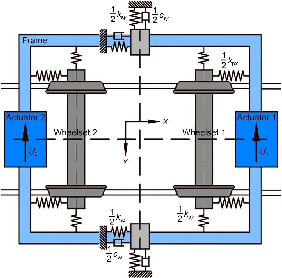
Fig.1 Bogie lateral dynamics model
The bogie is not a completely controllable and observable system.As a result,the control model is chosen as a subsystem with one frame and two actua‐tors.When the bogie is running,the lateral vibration of the frame is easy to measure.Therefore,by manip‐ulating the frame’s vibration,the wheelset motion can be controlled indirectly.In this study,the wheel-rail force caused by the lateral vibration of the wheelset is considered as the external excitation of the system.The lateral dynamic equation of the bogie model is as follows:
wherey=[yw1,φw1,yw2,φw2,yf,φf,ym1,ym2]T,the statesyw1,yw2,yf,ym1,andym2are the lateral displacements of wheelset 1,wheelset 2,frame,actuator 1,and actuator 2,respectively,and the statesφw1,φw2,andφfare the yaw angles of wheelset 1,wheelset 2,and frame,re‐spectively.M,C,andKare the mass,damping,and stiffness matrices of the system,respectively.The ma‐trixEis the influence of the control force on the sys‐tem,and the vectoruis the control force vector,u=[u1,u2]T,whereu1andu2respectively represent the control force generated by the actuators suspended on the front and rear end beams of the frame.The matrixQrepresents the influence of external excitation on the system,d(t) represents the external excitation such as track irregularity applied to the wheelset,andQd(t)represents the external force on the system caused by the yaw and lateral motions of the wheelset.To compare with the experimental results from the bogie scale test rig below,the model size is taken as one-fifth of the actual high-speed train bogie.In addition,the matri‐ces are presented in Data S1,and the values and defi‐nitions of the system parameters are listed in Table S1 in the electronic supplementary materials (ESM).
2.2 Inertial actuator model
The inertial actuator is one of the most widelyused elements in active control.In this study,the voice coil motor is selected as the actuator,as shown in Fig.2,which is a mass suspended on the frame in parallel by stiffness and damping.According to the real-time mo‐tion state of the bogie system,the actuator is driven to generate the control force through a certain control algorithm.The lateral stiffnesskmyand dampingcmyof the actuator are respectively defined as:
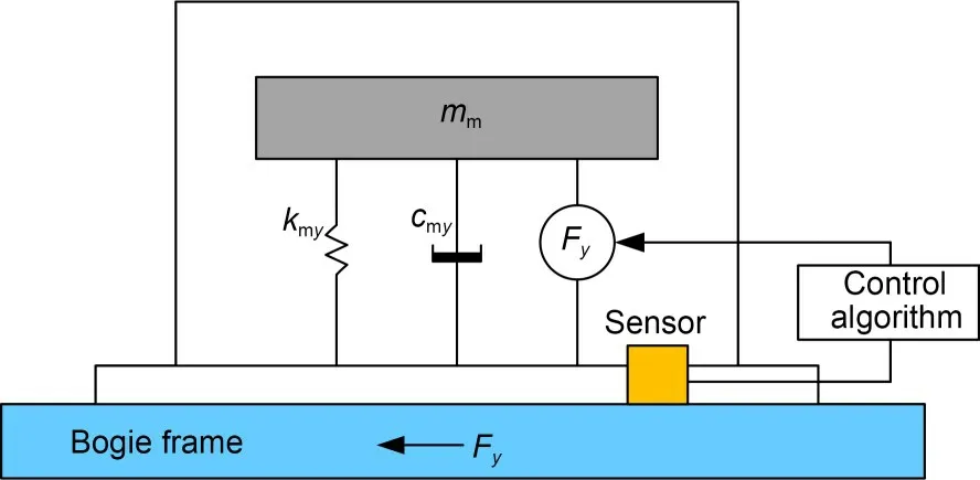
Fig.2 Inertial actuator dynamics model
wherefmis the natural frequency of the actuator,which is also known as the suspension frequency in Hz,ξmis the damping ratio,mmis the movable mass of each actuator in kg,yis the lateral displacement of actuator,andFyis the output lateral force.
The working principle of the inertial actuator is that when the electrified coil passes through the per‐manent magnetic field,it will produce an ampere force perpendicular to the magnetic field,which is deter‐mined by the lengthLof the conductor passing through the magnetic field,the magnetic inductionB,and the current intensityI.The voice coil motor converts the actual current into output lateral forceFy,which only depends on its design structural parametersKfand the current intensityI:
whereKfis defined as the force sensitivity of the voice coil motor in N/A.
2.3 Control strategy
The state equation of the bogie control system can be written as:
The system state vectorxis defined as:
The system matricesA,B,andFare defined as:
In this study,the linear feedback control algorithm is used to exert a control force on the frame,and the lateral motion of the wheelset is indirectly controlled to improve the hunting stability of the bogie system.
The control force vectoru(t) is the product of the frame’s lateral motion state and the feedback gain.The matrixKCis the control gain matrix (listed in the ESM),wherekd1andkd2are the displacement feedback coefficients of the front and rear end beams of the frame,respectively,andkv1andkv2are the velocity feedback coefficients of the front and rear end beams of the frame,respectively.The larger the feedback parameter,the greater the control force.By adjustingKC,the closed-loop system matrixAclis also modified to improve the stability of the bogie control system.
Since the control system is optimized under zero initial conditions,the control force cannot be directly included in the objective space.Therefore,the Frobe‐nius normKCTKCof the control gain matrixKCis ad‐opted and,by minimizing this norm,the total control energy is also minimized.The NSGA-II algorithm is used for the multi-objective and multi-parameter opti‐mization problem (Srinivas and Deb,1994;Beyer and Deb,2001;Deb et al.,2002;Li et al.,2023).Through the multi-objective optimization (MOOP) of the NSGA-II algorithm,four control parameters are optimized with two objectives of the bogie system sta‐bility index and the control effort.Finally,the MOOP results show that due to the symmetry of the bogie structure,whenkd1is close tokd2andkv1is close tokv2,the system has both good stability and small control effort.In addition,the displacement feedback has little influence on the stability of the bogie,sokd1andkd2are defined askd,which is taken as constant at 20.kv1andkv2are defined askv,and the velocity feedbackkvis the focus of the following research.
3 Lateral stability analysis
3.1 Linear system stability
In this section,the stability of the bogie control system is investigated based on the linear system analy‐sis method.The root locus curves of the bogie con‐trol system are shown in Figs.3 and 4.With steady increments of 5 km/h,the bogie running speedvis gradually increased from 5 km/h to 100 km/h.Each root locus has a set of 20 symbols “+”or “o”,each of which represents a distinct speed.A larger symbol “+”or “o”denotes a higher running speed,and the largest symbol “+”or “o”denotes 100 km/h.The vertical axis indicates the mode vibration frequencyf,and the horizontal axis indicates the stability indexζ.In this study,the stability indexζis defined as the ratio of the real part of the eigenvalue to the modulus corresponding to the vibration mode,which is not equal to the damp‐ing ratio,but is its opposite number.Therefore,a neg‐ative value of the stability index indicates that the sys‐tem is stable.The root locus curves at different posi‐tions in Figs.3 and 4 represent the vibration mode of different components of the bogie system.The largerζis,the less stable the system is.Mostly,a lowfrequency (within 10 Hz) hunting mode determines the bogie critical speed.
The symbol “o”curves shown in Fig.3 are the root locus of the bogie system without active control,and the symbol “+”curves in Fig.3 are the root locus when the control parameterkvgradually increases to 100,300,500,and 1000,respectively.It can be seen from Fig.3 that the bogie critical speed without active control is about 45 km/h,while theζof bogie hunting mode is obviously affected by the control force.Whenkvincreases to 1000,ζof bogie hunting mode is less than −0.2 at the speed of 100 km/h.Therefore,with the increase of the control force,the stability of the system is also improved.The active control can effec‐tively improve the critical speed of bogie hunting from 45 km/h to over 100 km/h.
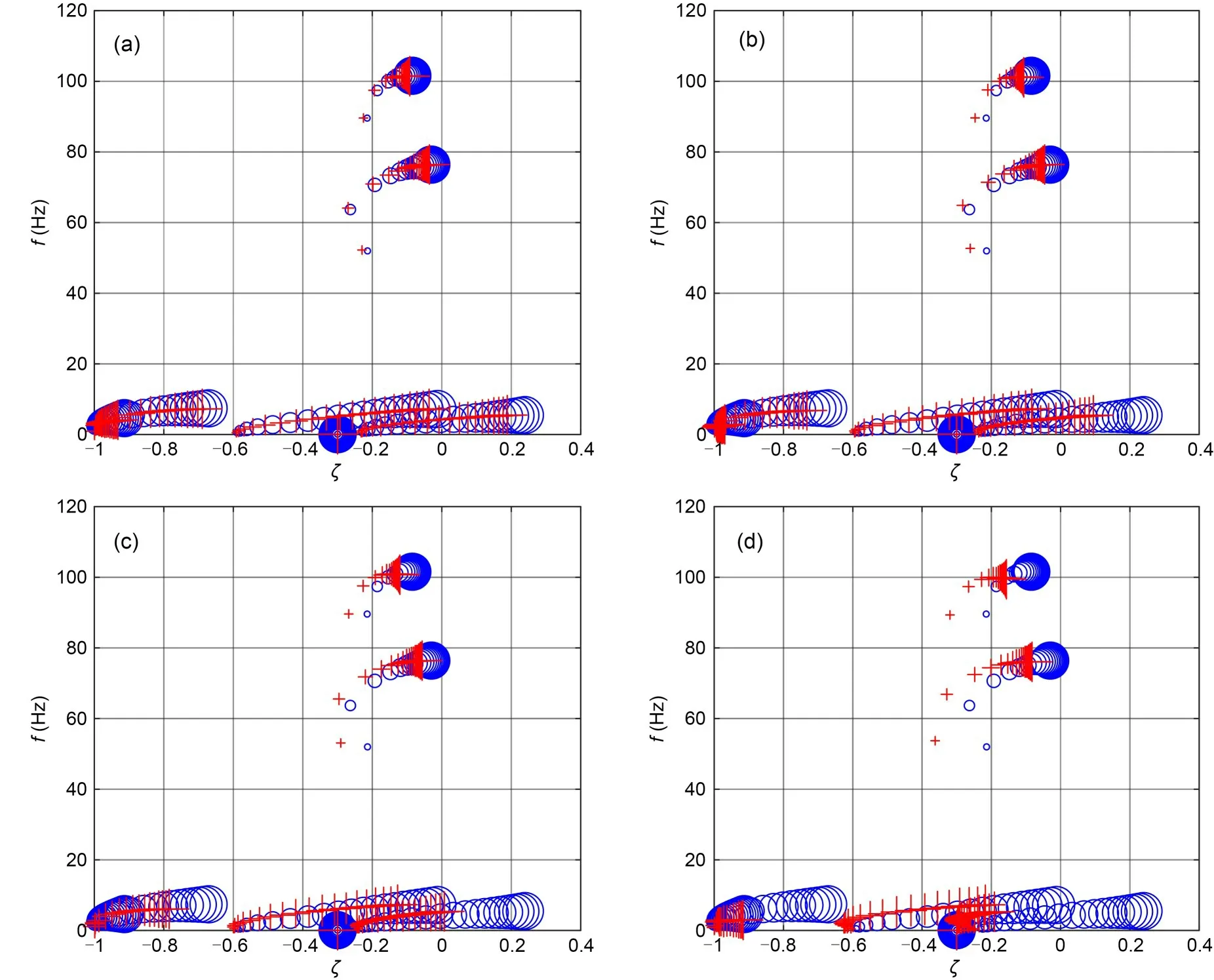
Fig.3 Root locus with different kv and v: (a) kv=100;(b) kv=300;(c) kv=500;(d) kv=1000
3.2 Stability with time-delay
Time-delay is unavoidable in a feedback control system.The phase of the active control force can be changed by the time-delay in control,which has a negative impact on control performance.The influence of time-delay in the control system on the bogie stability is analyzed by using the continuous time approximation(CTA) method (Sun,2009).According to a series of simulation results,four representative time-delays are selected for analysis in this section.As shown in Fig.4,the symbol “+”curves are the results when the delayτis set to 5,10,30,and 40 ms,respectively and,for comparison,the symbol “o”curve is the re‐sult whenkvis 1000 without delay.As shown in Fig.4,the delay around 10 ms has little effect on the stability of the low-frequency bogie hunting.However,a minor delay of 5 ms will cause the root locus curve of the high-frequency (80 Hz) mode of the frame lateral vibration to shift to the right and increaseζto 0,and lead to the instability of the bogie system.When the delayτexceeds 30 ms,theζof the low-frequency(within 10 Hz) hunting mode at high speeds increases sharply and becomes positive,and the bogie system is obviously unstable under the control with a 40-ms time-delay.The time-delay of the control system is reflected in the delay of the phase of the output con‐trol force response.The phase delay of the force out‐put response increases as the time-delay increases.Highfrequency mode vibration has a short time period,while low-frequency mode vibration has a long time period.Therefore,a small time-delay has a great influ‐ence on the high-frequency mode,but little influence on the low-frequency mode.When the time-delay is con‐siderable,it has a similar effect on the high-frequency mode as a small time-delay,but it has a significant im‐pact on the low-frequency mode.
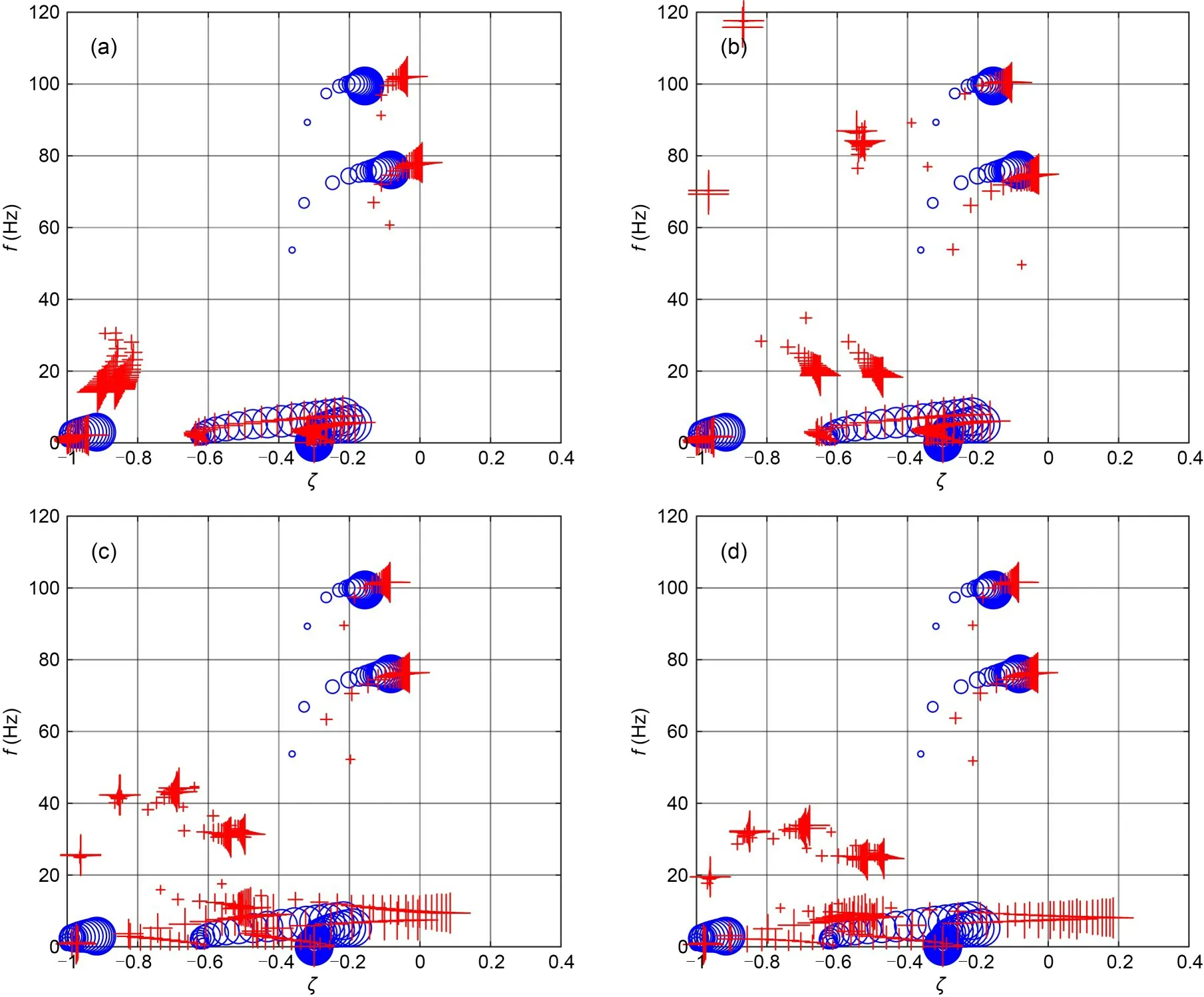
Fig.4 Root locus with different τ and v: (a) τ=5 ms;(b) τ=10 ms;(c) τ=30 ms;(d) τ=40 ms
In conclusion,the active control of the frame lat‐eral vibration state can effectively improve the bogie critical speed.The larger the control effort,the more stable the bogie.However,in practice,the achievable control effort needs to be considered.The time-delay in control has a significant impact on the system’s sta‐bility,which should be taken into account during the actual design of control system parameter modification.The bogie critical speed is mostly determined by the low-frequency (within 10 Hz) hunting mode,and a delay larger than 30 ms will reduce the low-frequency hunting stability margin of the bogie system.In this study,the active control force acts directly on the frame,and the control force is obtained by the vibration feed‐back of the frame.As a result,the active control force may be directed in the same direction as the vibration of the frame,which will aggravate the frame vibration and lead to instability of the bogie system.As Fig.4a depicted,a specific delay of about 5 ms related to lateral vibration natural frequency of the frame will cause frame high-frequency vibration instability.There‐fore,the higher mode (80 Hz) of frame vibration is also important for the bogie stability.
3.3 Effect of the suspension parameter
Since the primary lateral suspension parameter has a great influence on the bogie hunting stability and the parameter adjustment function of the following bogie test rig,this section discusses the effect of the primary lateral stiffnesskpyon the bogie stability at three different running speeds,with the control param‐eterkvset to 1000.As shown in Fig.5,the horizontal axis is the time-delayτ,and the vertical axis is the maximum stability indexζmaxof the bogie hunting mode.The greater theζmax,the worse the stability.Whenζmaxis greater than 0,the bogie system becomes unstable.Fig.5 shows the results of the bogie hunting stability with active control at speeds of 20,50,and 80 km/h,respectively,with distinct curves represent‐ing various primary lateral suspension stiffnesseskpy(0.5–5.0 kN/mm).
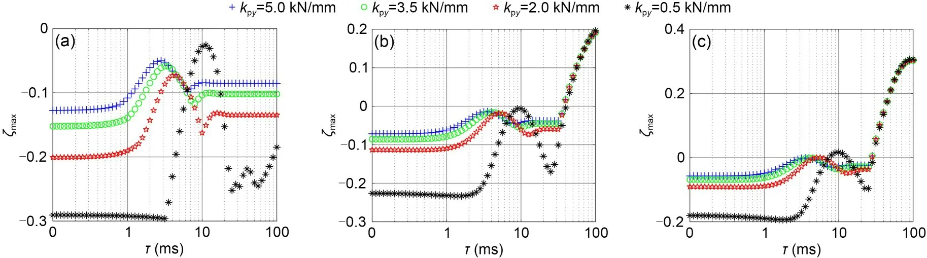
Fig.5 Linear system stability with different kpy and τ: (a) v=20 km/h;(b) v=50 km/h;(c) v=80 km/h
As shown in Fig.5,when the time-delayτis 0 ms,the value ofζmaxis the least askpyis 0.5 kN/mm.However,the value ofζmaxfluctuates greatly with the time-delayτwhen the system adopts a smallvalue of 0.5 kN/mm forkpy,and the bogie hunting stability will be greatly reduced whenτis around 10 ms.When the delay is within the small value of 10 ms,there are fourζmaxpeaks corresponding to the four differentkpywhere theζmaxincreases rapidly.When thekpyis 0.5,2.0,3.5,and 5.0 kN/mm,the delays corresponding to theζmaxpeak are about 10,5,3,and 2 ms,respectively,which is related to the lateral vibration natural fre‐quency of the frame.It can be concluded that a smaller lateral suspension stiffnesskpyis beneficial to the bogie hunting stability,but the small delay corresponding toζmaxpeaks increases with the decrease ofkpy.Further‐more,the delay has a great influence on the stability of the bogie system at high speeds.The system be‐comes unstable when the delay exceeds 40 ms at a speed of 50 km/h,while system instability occurs as the delay exceeds 30 ms at a speed of 80 km/h.
3.4 Time domain simulation
The railway system is a nonlinear dynamic sys‐tem.That is mainly reflected in the nonlinear charac‐teristics of the wheel-rail contact relationship and sus‐pension elements,so the stability of the nonlinear sys‐tem cannot be ignored.In this section,the nonlinear characteristics of wheel-rail contact geometry and creep saturation are considered,and the bogie nonlinear dy‐namic model is established,with the direct integration method used to analyze the nonlinear stability of the bogie system (Srinivas and Deb,1994;Deb et al.,2002).
Fig.6 shows the time-domain curve of wheelset lateral displacement under different conditions,with the bogie speed set to 50 km/h and the control parameterkvset to 1000.It can be seen that the bogie hunting instability is visible at the speed of 50 km/h,and that active control can significantly improve the bogie stability at high speed.The active control will be ren‐dered ineffective by a large delay of 30 ms,while a small delay of 5 ms will also cause the bogie to be‐come unstable due to high-frequency vibration of the frame.A 10-ms delay has little effect on the system stability,and the wheelset lateral displacement conver‐gence speed is even slightly faster than that without the delay.Therefore,it is necessary to avoid the unfa‐vorable impact of control delay on bogie hunting stability.
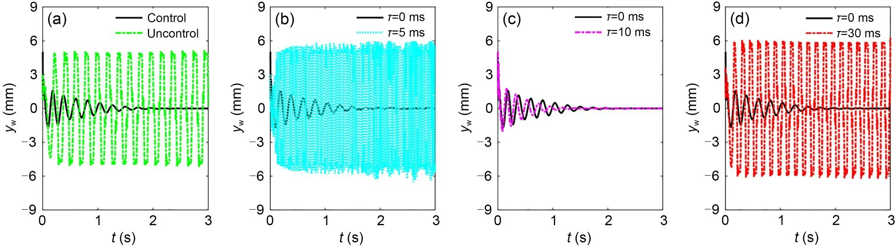
Fig.6 Wheelset lateral displacement in the time-domain bogie scale test rig: (a) control and uncontrol;(b) control with τ=0 or 5 ms;(c) control with τ=0 or 10 ms;(d) control with τ=0 or 30 ms
4 Experimental analysis
4.1 Bogie scale test rig
The bogie test rig at 1:5 scale is shown in Fig.7,it comprises wheelsets,frame,rolling rails,driving motor,and inertial actuators.The primary suspen‐sion works between the frame and the wheelset,and consists of straight leaf springs.The stiffness of the primary suspension can be modified by changing its arrangement angle.To drive the wheelsets,a driving motor is directly linked to the rolling rail and the run‐ning speed is changed by adjusting the rotating speed of the driving motor.In addition,the test rig also con‐tains a track excitation generator,an active control platform,and the signal acquisition module.

Fig.7 Bogie scale test rig
The active control platform is made up of a DSP(digital signal processing technology) processor and a control algorithm module (built by Simulink software as shown in Fig.8),which plays a core role in adjust‐ing the velocity feedback coefficientkv,displacement feedback coefficientkd,and time-delay parameterτ.In general,the delay of control system mainly comes from the controller and actuator themselves.However,to facilitate the analysis and research,the method of actuator delay compensation is proposed by adjusting the parameters of the control platform and the sensor in this experiment.The delay in the control system is simulated by just adjusting the parameterτof the added time-delay module in the control loop.The value ofkdis taken as a constant of 20 based on the multi-objective optimization results,and the next experimental study concentrates onkvandτ.The signal acquisition module is mainly composed of a wire displacement sensor,which can monitor and collect the lateral movement information of the frame in real time.Finally,according to the control algorithm,the inertial actuator moves the inertial mass and generates an inertial force in the frame.
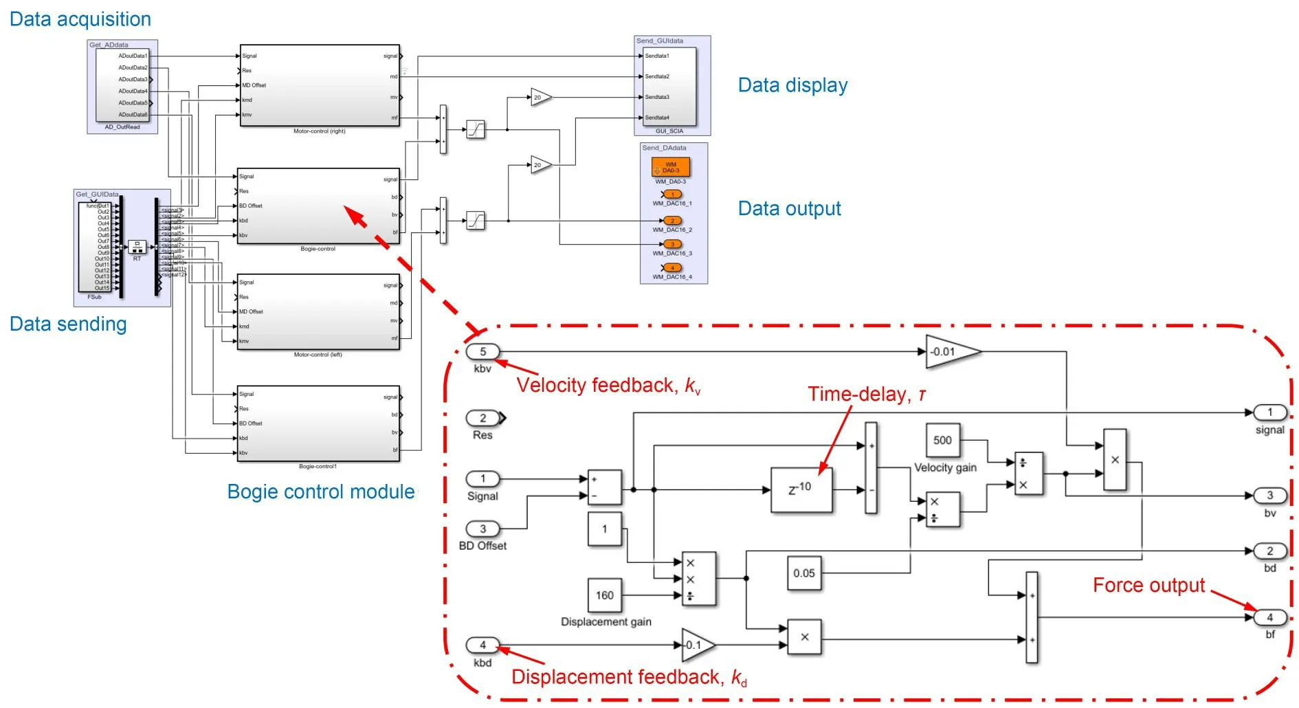
Fig.8 Simulink control algorithm module
The voice coil motor is selected as the inertial actuator,and consists of the mover (inertial mass and electromagnetic coil) and stator (permanent magnet).Moreover,the voice coil motor has the characteristics of simple structure,high running speed,and fast re‐sponse.The inertial force applied to the bogie frame will change alternately with the input voltage.There‐fore,it is necessary to make the force generated by ac‐tuator output as close as possible to the control force calculated by ideal control command.The displace‐ment curves of the inertial model simulation result and the actuator experimental result are shown in Fig.9a,and their associated active control forceshare shown in Fig.9b.
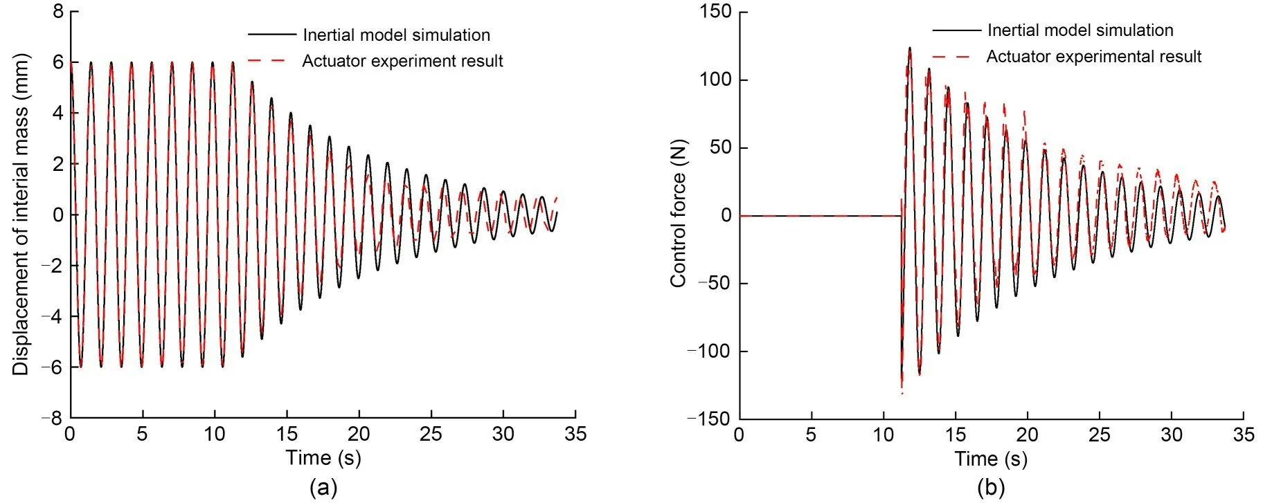
Fig.9 Time-domain response of the inertial actuator: (a) displacement of inertial mass;(b) control force
4.2 Effect of control parameters
In the experiment,intermittent active control is used to make the comparison of control effects.The lateral displacement of the bogie frame measured by the sensor under different control parameters is shown in Fig.10.The running speed of the wheelset is set to 50 km/h,and the control parameterskvare set to 100,300,500,and 1000,respectively.
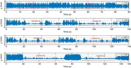
Fig.10 Bogie frame lateral displacement with different kv
It can be seen from Fig.10 that the bogie frame vibrates significantly at 50 km/h,and the lateral dis‐placement amplitude of the bogie frame approaches 5 mm.However,increasing the control force can effi‐ciently reduce the amplitude of the frame vibration.The vibration curve is close to convergence and the control effect is optimal when the control parameterkvincreases to 1000.As a result,by increasing the con‐trol force,the active control of bogie lateral vibration can significantly improve the hunting stability of the bogie system at high speeds.
4.3 Effect of control parameters
The influence of control system time-delayτon bogie stability was then investigated.The lateral dis‐placement of the frame under different delays is shown in Fig.11 in which the running speed of the bogie is 50 km/h and the control parameterkvis 1000.
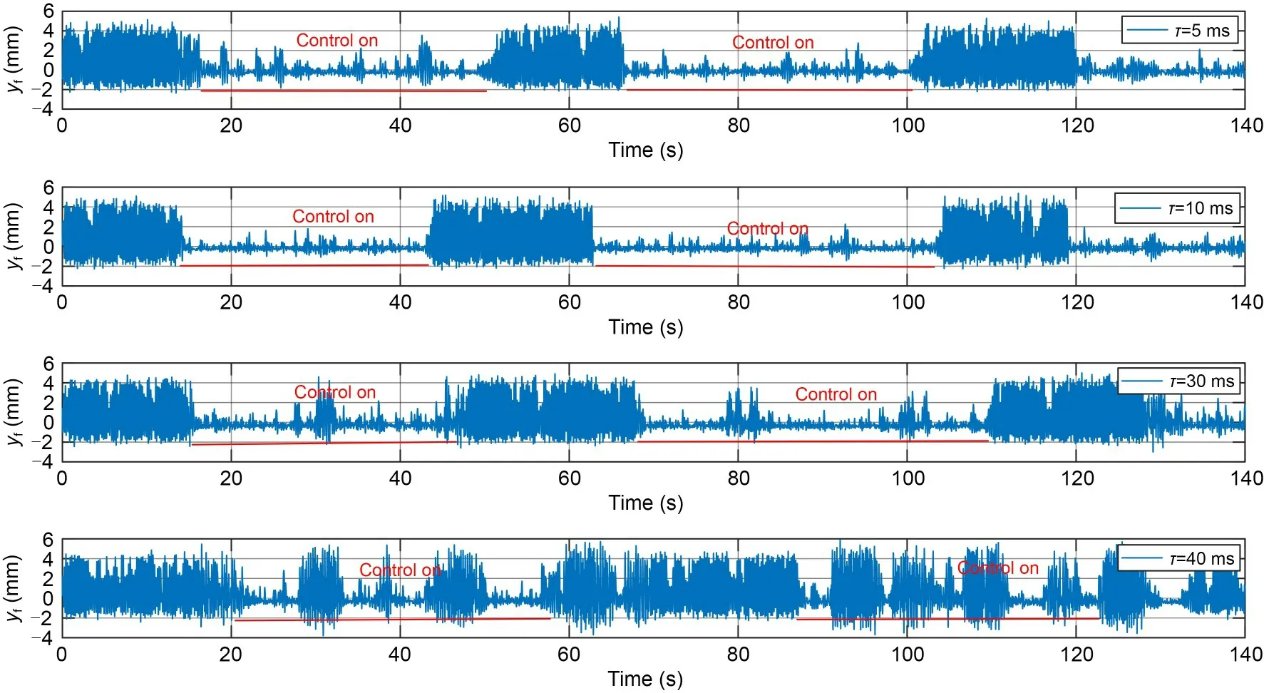
Fig.11 Bogie frame lateral displacement with different τ
It can be seen from Fig.11 that the 10-ms delay has little effect on the bogie’s hunting stability,but the delay of 5 ms related to the frame’s lateral vibra‐tion natural frequency will increase the frame’s lateral vibration.The stability of the bogie system is signifi‐cantly reduced when the delay exceeds 30 ms,and the delay of 40 ms will make the active control ineffec‐tive,resulting in severe frame vibration and bogie system instability.As a result,a large or small delay is not beneficial to the stability of the system,and that should be taken into account in the actual design of control system parameter adjustment.
4.4 Power spectral density analysis
Finally,power spectral density curves are obtained through frequency domain analysis,as shown in Fig.12,in which the running speed of the bogie is 50 km/h.It can be seen that the bogie hunting frequency without control is around 5.8 Hz (matching the low-frequency hunting mode in Fig.3),and the curve has no main peak under active control without a delay.The curve peak shifts to the right when the active control delay is 40 ms,and the bogie’s hunting frequency increases to around 7.8 Hz.As a result,the active control of frame lateral vibration can effectively improve the bogie stability margin,but the delay of the control system would change the phase of the active control force,resulting in control failure and the increase of bogie hunting frequency.
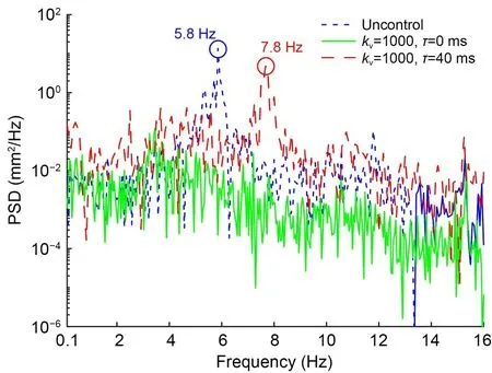
Fig.12 Power spectral density (PSD) with kv and τ
5 Conclusions
In this study,the bogie active stability method based on frame lateral vibration control is proposed;it can effectively improve the critical speed of a bogie system from 45 km/h to over 100 km/h.The frame velocity feedback has a bigger effect on stability than the displacement feedback.The bogie’s lateral stability is improved by increasing the velocity feedback coef‐ficientkv.However,in addition to the stability of the closed-loop system,the energy efficiency of the con‐troller should also be considered.
Through the bogie scale test rig,the effect of the control system time-delay on the stability of the bogie system at a speed of 50 km/h was analyzed.The sys‐tem stability is unaffected by an appropriate delay of roughly 10 ms.A minor delay,such as around 5 ms,causes high-frequency mode instability due to frame lateral vibration,while a large delay,such as more than 30 ms,causes low-frequency mode instability due to bogie hunting,both of which are detrimental to system stability.This should be taken into account in the actual design of control system parameter adjustment.
The smaller lateral suspension stiffnesskpyis ben‐eficial to the bogie hunting stability.However,when the system adopts a small value of 0.5 kN/mm forkpy,the stability indexζmaxfluctuates dramatically with the time-delayτ,and the bogie hunting stability is greatly lowered whenτis around 10 ms.The minor delay that leads to system instability grows whenkpy,which is re‐lated to the frame’s natural lateral vibration frequency,decreases.
Acknowledgments
This work is supported by the National Railway Group Sci‐ence and Technology Program (Nos.N2020J026 and N2021J028)and the Independent Research and Development Projects of Traction Power State Key Laboratory (No.2022TPL-T02),China.
Author contributions
Yadong SONG designed the research.Hu LI and Jun CHENG processed the corresponding data.Yadong SONG wrote the first draft of the manuscript.Jun CHENG helped to orga‐nize the manuscript.Yuan YAO revised and edited the final version.
Conflict of interest
Yadong SONG,Hu LI,Jun CHENG,and Yuan YAO de‐clare that they have no conflict of interest.
 Journal of Zhejiang University-Science A(Applied Physics & Engineering)2023年7期
- Journal of Zhejiang University-Science A(Applied Physics & Engineering)的其它文章
- Numerical investigation of the effect of geosynthetic clay liner chemical incompatibility on flow and contaminant transport through a defective composite liner
- Monotonic uplift behavior of anchored pier foundations in soil overlying rock
- Fractal analysis of small-micro pores and estimation of permeability of loess using mercury intrusion porosimetry
- Underwater minirobots actuated by hybrid driving method
- Square cavity flow driven by two mutually facing sliding walls
- Analytical solution of ground-borne vibration due to a spatially periodic harmonic moving load in a tunnel embedded in layered soil