
Underwater minirobots actuated by hybrid driving method
2023-07-24 10:07XinghongYEYangYANGPengchengJIAOZhiguoHELingweiLI
Xinghong YE ,Yang YANG ,Pengcheng JIAO ,Zhiguo HE ,Lingwei LI
1Institute of Port, Coastal and Offshore Engineering, Ocean College, Zhejiang University, Zhoushan 316021, China
2Engineering Research Center of Oceanic Sensing Technology and Equipment of Ministry of Education, Zhejiang University, Zhoushan 316021,China
3Department of Biomedical Engineering (BME), National University of Singapore, Singapore 119077, Singapore
4Key Laboratory of Marine Geotechnical Engineering and Materials, Zhoushan 316021, China
5Authors contributed equally to this work
Abstract: Underwater minirobots have attracted significant interest due to their value in complex application scenarios.Typical underwater minirobots are driven mainly by a soft or rigid actuator.However,soft actuation is currently facing challenges,including inadequate motional control accuracy and the lack of a continuous and steady driving force,while conventional rigid actuation has limited actuation efficiency,environmental adaptability,and motional flexibility,which severely limits the accomplishment of complicated underwater tasks.In this study,we developed underwater minirobots actuated by a hybrid driving method (HDM) that combines combustion-based actuators and propeller thrusters to achieve accurate,fast,and flexible underwater locomotion performance.Underwater experiments were conducted to investigate the kinematic performance of the minirobots with respect to the motion modes of rising,drifting,and hovering.Numerical models were used to investigate the kinematic characteristics of the minirobots,and theoretical models developed to unveil the mechanical principle that governs the driving process.Satisfactory agreement was obtained from comarisons of the experimental,numerical,and theoretical results.Finally,the HDM was compared with selected hybrid driving technologies in terms of acceleration and response time.The comparison showed that the minirobots based on HDM were generally superior in transient actuation ability and reliability.
Key words: Hybrid driving method (HDM);Underwater minirobots;Operation reliability;Transient actuation
1 Introduction
Autonomous underwater vehicles (AUVs) have been developed to carry out various field exploration tasks,e.g.,monitoring the health of underwater struc‐tures (Neto et al.,2014) and extreme disaster investi‐gation (Sahoo et al.,2019).Such tasks typically re‐quire good object pertinence,impressive mobility,and satisfactory control accuracy (Albiez et al.,2015;Dinmohammadi et al.,2019).Recently,AUVs have shown reliable performance in various applications,such as deep-ocean exploration (Iscar et al.,2018),ob‐ject detection (Song et al.,2021),and maintenance of underwater structures (Sahoo et al.,2019).AUVs are actuated by various methods,such as multi-propeller cooperative propulsion (An et al.,2019),hydraulic propulsion (Zhou et al.,2013),vector propulsion (Chen et al.,2020),and waterjet propulsion (Xin et al.,2013).These actuation methods,however,limit the environ‐mental adaptability and motional flexibility of AUVs(Antonelli et al.,2004).This results in unsatisfactory interactions between the robot systems and previously unmapped marine environments with accidental dis‐turbance,e.g.,creature disturbance (Li et al.,2014),fluid disturbance (Yao and Zhao,2018),and obstacle disturbance (Das et al.,2016).
Inspired by natural creatures,soft robotics and actuators have been developed in recent years to solve the shortcomings of rigid actuators.Unlike conventional rigid components,flexible functional materials undergo compliant and large deformations that provide unique advantages such as flexibility (Li et al.,2018;Zhang et al.,2019),light weight (da Cunha et al.,2020;Zhang et al.,2020),and good environmental interaction (Rus and Tolley,2015;Lee et al.,2017;Cheng et al.,2018).Based on multifunctional flexible materials,under‐water soft actuators can be actuated by various envi‐ronmental stimuli (Lee et al.,2010;Laschi et al.,2016;Banerjee et al.,2018).A pneumatically powered soft robot with a design based on the pressure response phenomenon,was found to be resilient to a variety of adverse environmental conditions (Tolley et al.,2014b).A biomimetic turtle flipper actuator,actuated by a shape memory alloy (SMA),was developed to per‐form continuous motions mimicking the forelimb of the green turtle,Chelonia mydas.This design showed better bionic ability than rigid robots (Song et al.,2016).A high-voltage-induced dielectric elastomer (DE) was designed for use in a manta-inspired underwater soft robot that can swim in the Mariana Trench,withstand‐ing the extremely high pressure in the deep sea (Li TF et al.,2017;Li GR et al.,2021).Those studies illus‐trate the applicability of soft actuators manufactured using flexible functional materials in harsh application scenarios.However,these soft actuators have a limited response time and actuation acceleration.Therefore,improvements in the kinematic performance of soft actuators (i.e.,reaction ability and locomotion perfor‐mance) are needed,while maintaining good maneu‐verability and environment adaptability.
Using the extreme reaction of combustion (ignit‐ing premixed methane and oxygen gas),triple-pedal soft robots with pneu-nets were designed to generate explosive bursts of pressure for on-land high-speed soft robots (Tolley et al.,2014b).A transient driving method (TDM) was proposed to quantitatively study the combustion-based driving method,and the theoret‐ical performance of the TDM-enabled soft actuator was studied (Yang et al.,2020,2022;He et al.,2023).Untethered underwater soft jumpers were developed to demonstrate the applicability of TDM-based soft robots in a water-air multiphase environment (Wang et al.,2021).The reported soft jumpers were able to leap out of the water by generating powerful thrust to reach an average distance of 2.5 times their body length from the water-air interface and 4.5 times the body length from the initial location,in a time of less than 0.4 s.However,the TDM is currently facing chal‐lenges,including inadequate motional control accuracy and the lack of a continuous and steady driving force,and the noise generated by combustion is not condu‐cive to underwater monitoring and other operations.
Here,we report a novel type of underwater mini‐robot actuated by the hybrid driving method (HDM)that combines conventional driving methods with TDM,i.e.,that combines combustion-based actuators with propeller thrusters to achieve accurate,fast,and flexi‐ble underwater locomotion performance.This class of robot-hybrids,comprising hard and soft systems func‐tioning synergistically,is capable of performing tasks that neither can do alone.Considering the characteris‐tics of transient velocity movement actuated by com‐bustion and the continuous driving force provided by propeller thrusters,these devices have prospects for application in many underwater scenarios involving minirobots,e.g.,underwater transient starting and brak‐ing,escaping from being stuck,instantaneous obstacle avoidance,underwater monitoring,and underwater grasping.Table 1 compares aspects of performance of our proposed method with those of similar published methods.To investigate the operational reliability and transient actuation ability,the minirobots were tested in the rising,hovering,and drifting modes.The HDMbased minirobots had a high transient starting velocity of 3–4 m/s.Moreover,the propellers were able to maintain the speed while providing more precise move‐ments.A numerical model based on the dynamic mesh method and a theoretical model based on the drag analysis method were developed,and good agreement wasobtained from a comparison.Parametric comparisons were conducted to demonstrate the effectiveness of the HDM in controlling the locomotion of the miniro‐bots.Finally,the HDM underwater minirobots were compared with existing soft robots driven by different technologies,e.g.,shape memory polymers (SMP),magnets,electromagnets (EM),gels,thrusters,and combustion,in terms of their response time and actua‐tion acceleration.The rest of this paper is organized as follows: Section 2 presents the design principle and fabrication process of the underwater minirobots.Sec‐tion 3 presents the experimental study to investigate the kinematic characteristics of the minirobots.Sec‐tion 4 develops the numerical and theoretical models to explain the physical principles of the motion process.Section 5 compares and discusses the experimental,numerical,and theoretical results.Section 6 presents the limitations of this study and proposes future work.Section 7 concludes the main findings of this study.The electronic supplementary materials (ESM) provide further details on the experimental performance of the underwater minirobots actuated by HDM.
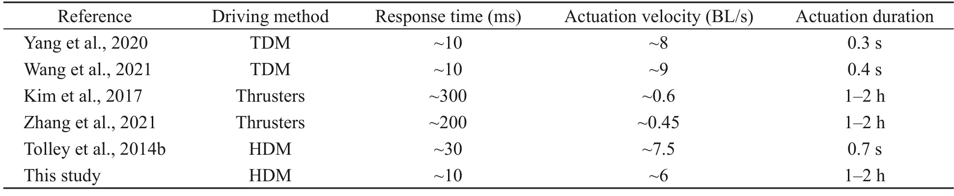
Table 1 Comparison of the performances of the proposed HDM and similar published driving methods
2 Design and fabrication
2.1 Design principle
This section introduces the conceptual and me‐chanical design of the underwater minirobots actuated by HDM.Fig.1a illustrates the detailed structure and corresponding dimensions of the minirobots,includ‐ing the combustion actuator,propeller thrusters,and shell.The combustion actuator is designed with a pipe to input premixed gas (oxygen and propane) in certain ratios,a chamber to provide the space for premixed gas storage and reaction,a spark ignitor for combus‐tion inspiration,and a soft membrane (i.e.,a hyperelastic membrane) to generate rapid,strong,and recov‐erable deformations (Fig.1b).Note that all the required electronic components (e.g.,the single-chip microcom‐puter (SCM),battery,and wires) are organized and stored in the shell.The working principle of the com‐bustion actuator can be summarized as follows: pro‐pane and oxygen gas is released from the gas cylin‐ders and then accurately premixed by the electronic flow meter.After feeding the premixed gas into the chamber,combustion ignition can be triggered by the high voltage release phenomenon at the generator tip.The dramatic pressure changes in the chamber transiently expand the soft membrane into volcano-like shapes within~9 ms (Yang et al.,2020),which power‐fully push against the ground for rapid underwater jumps.The process from initiation to expansion of the soft membrane is the response process driven by com‐bustion,and the response time is the indicator of reac‐tion ability (Wang et al.,2021).Fig.1c shows the rigid actuation principle of the minirobots driven by the propeller thrusters.Namely,clockwise counter-acting torques are produced byM2andM4,and anticlock‐wise counter-acting torques are produced byM1andM3.The minirobots are powered by 9-V direct-current(DC) voltage.The rotational direction and speed of the propellers are controlled by the electrical speed con‐trollers (ESCs).To realize the rising,hovering,and drifting motion modes,the propulsion strategies of the propellers are designed as follows: In the rising mode,the increase in the rotational speed of the pro‐pellers overcomes the robot’s weight to perform lift‐ing.In the hovering mode,the lifting reaches the force’s equilibrium for the minirobots.In the drifting mode,horizontal thrusts are produced by setting dif‐ferent rotational speeds for the offside propellers.Fig.1d presents a flowchart of the HDM.The SCM timing program,gas amount,and ESC parameters are preset,and correspond toT1,T2,Vgas,andF1–4in the initial parameter,whereT1is the actuation time of combustion,T2is the actuation time of propulsion,Vgasis the gas amount,andF1–4is the propulsion force.The timing program in the SCM is written so as to control the channel switch of the connected relay,and the relay controls the start and stop of the actuation.The initial conditions,consisting ofT1,T2,Vgas,andF1–4,are experimentally pre-determined to accurately control different motion modes.Jumping is generated by the deformation of the soft membrane due to com‐bustion atT1and propulsion is generated by the pro‐pellers starting atT2.The SCM functions as the con‐trol center to accurately separate these initial conditions.
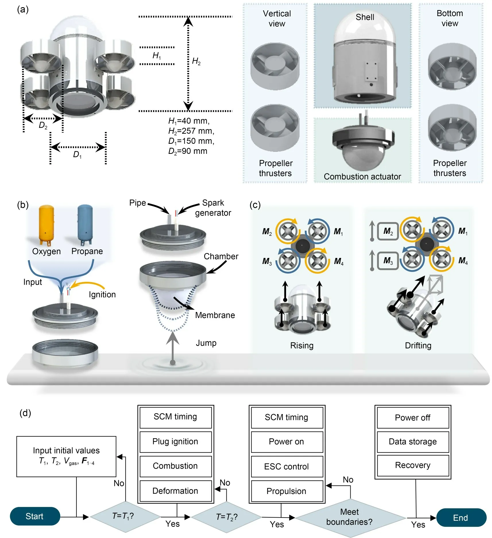
Fig.1 Design principle and dimensions of the underwater minirobots actuated by HDM: (a) overall design and dimensions of the minirobots;(b) structures and the actuation principle of the combustion actuator;(c) propulsion principle of the propeller thrusters;(d) flowchart illustrating the control principle of the robot actuated by HDM.T is the time of the motion process
2.2 Motion modes of the minirobots
Analyses of the motion strategies of the miniro‐bots are shown in Fig.2a.The rising,drifting,and hovering modes are defined asθ≤10°,45°≤θ≤55°,andθ≤10°,respectively,to quantitatively specify these three modes (Figs.2a,2b,and 2c).In addition,and ∆y≤HRobotare defined for the three modes,respectively.θ,∆x,∆y,andHRobotare the de‐flection angle,the horizontal displacement,the vertical displacement,and the height of the robot,respectively.
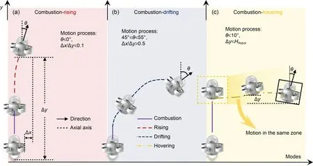
Fig.2 Motion strategies and quantitative definitions of the three planned motional modes: (a) rising mode;(b) drifting mode;(c) hovering mode.References to color refer to the online version of this figure
2.3 Fabrication
Table 2 presents the geometric parameters and material properties of the HDM minirobots.The fabri‐cation process (Fig.3) is divided into three steps:molding fabrication of membranes,3D printing of the main body,and assembly of the fabricated components and electronic devices.The molding fabrication pro‐cess contains five steps (Fig.3a): (1) equal amounts(70 mL) of Dragon Skin 30 silicon rubber gels A and B are poured into a beaker (Yang et al.,2020).(2) An agitator is applied to stir and fully mix the gels.(3) The mixture is perfused into a 3D-printed mold.(4) A vac‐uum generator is applied to deform and eliminate any bubbles in the soft membranes.(5) The mixture is cured at normal room temperature (25 ℃) for more than 8 h.
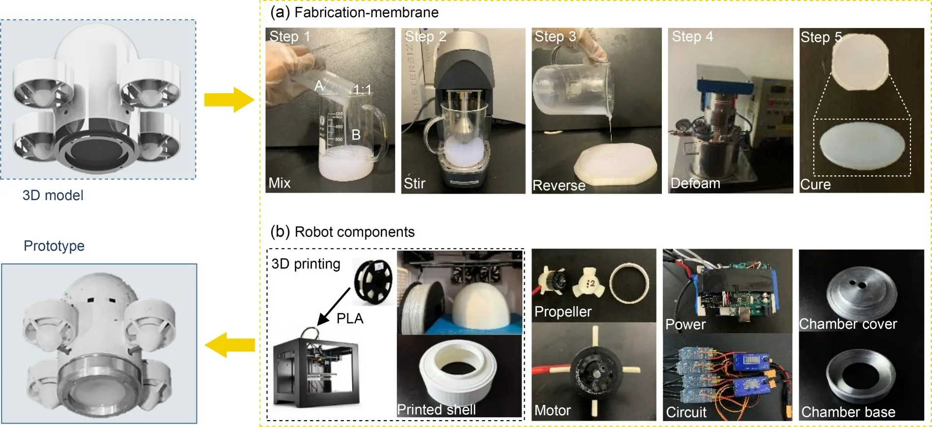
Fig.3 Fabrication processes of the underwater minirobots: (a) five fabrication processes of the soft membrane;(b) 3Dprinted head and shell,electronics (i.e.,propeller,motor,SCM,and ESC),and chamber cover and base in the HDM minirobots.PLA represents the polylactic acid
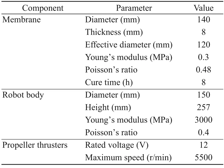
Table 2 Detailed dimensions of components
The HDM minirobots comprise a head,shell,propellers,motors,SCM,ESCs,chamber cover,and chamber base (Fig.3b).The head and shell,fabricated with the polylactic acid (PLA) material,contain hol‐lows to provide spaces for the power supply and other electronic components.The material properties of the PLA material can be found in Table 2.PLA material used for 3D printing has high biocompatibility and de‐gradability,is non-toxic to humans,and can directly enter soil organic matter or be absorbed by plants.Ac‐cording to the material properties and the structural parameters of the robot,we estimated the bearable pressure of the robot to be~1.08 MPa and the maxi‐mum working depth to be~108 m.The propeller thrust‐ers are evenly installed on the shell in the circumfer‐ential direction.Two mounting holes are designed on the top surface of the chamber cover to assemble the gas tube and spark generator.
3 Experimental study
In this section,we describe experimental studies conducted following the three motion modes set above,aiming to verify: (1) rapidity in underwater motion,i.e.,a superior actuation acceleration and response time by combustion actuators,(2) continuity in underwater motion,i.e.,a continuous and stable driving force pro‐vided by continuous propeller thrusters,and (3) con‐trollability in underwater motion,i.e.,the trajectory of the robot within the preset parameter range.
3.1 Experimental setup
In this section we introduce the experimental setup of the underwater testing for the HDM minirobots.The equipment comprised a recording system,testing environment,and gas system.Fig.4a shows the setup of the recording system that consisted of a high-speed camera with a speed of up to 12000 frame/s,a corre‐sponding personal computer (PC) to store the large amount of image data and for switching the camera,a water tank placed in front of the camera,and the HDM minirobots set at the bottom of the water tank.Fig.4a also shows the testing environment setup.The water tank was 0.9 m long,0.9 m wide,and 1.8 m high,and held water up to 1 m deep.Given the body height of 257 mm for the minirobots (Fig.1a),the water tank provided a motion range of 4 times the robot height.The gas system setup (Fig.4b) contained an explosionproof cabinet for storing the oxygen and propane cyl‐inders,two high-pressure pipelines used to transmit these two gases,pressure gauges,check valves,flame arresters,and an electronic flow meter that accurately controlled input gas amounts.The oxygen and propane were mixed by the gas system and air,and fed into the chamber through the input tube of the combustion actuator.
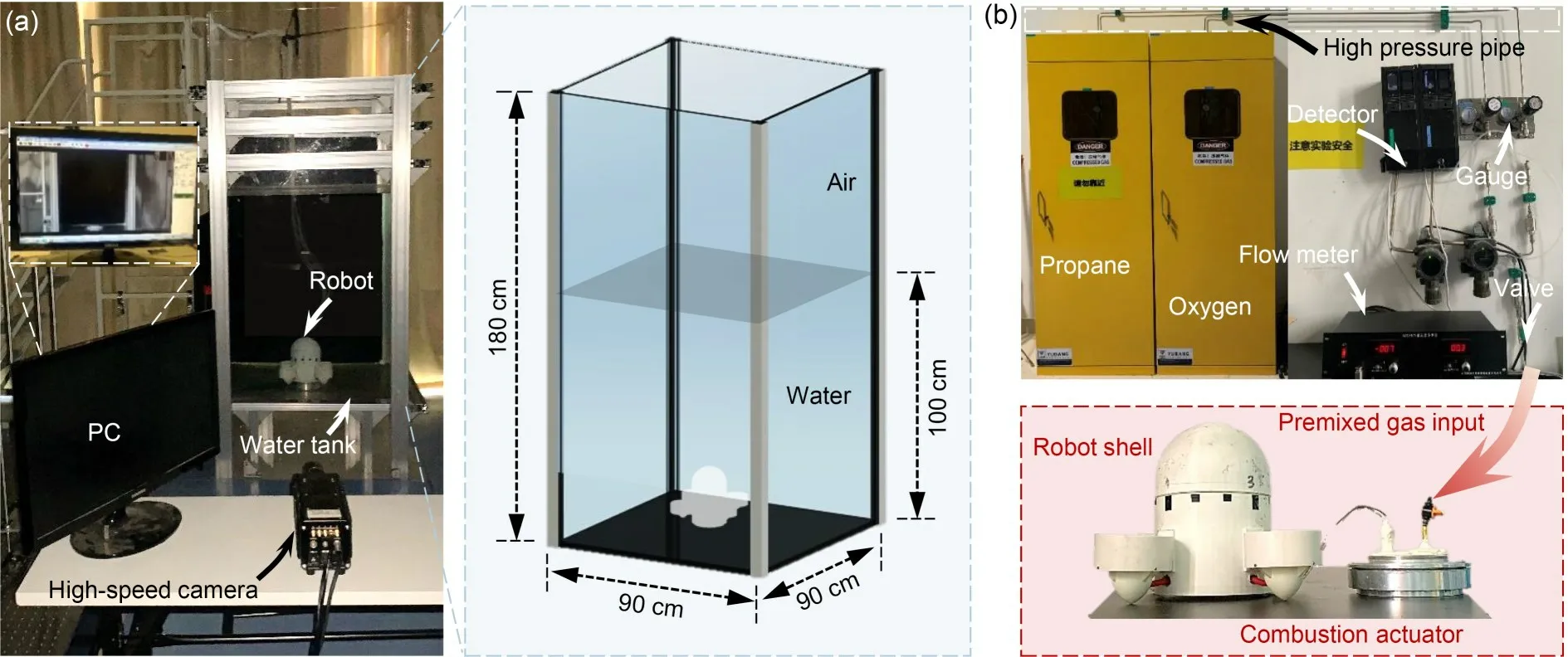
Fig.4 Experimental setup of the underwater soft robots: (a) setup for the underwater testing platform;(b) setup for gas input system
3.2 Experiment results
To investigate the kinematic performance of the HDM minirobots,motions generated by different gas amounts and durations were captured by the high-speed camera (Table 3).The captured images were automati‐cally processed in MATLAB by the binarization method to obtain outlines of the minirobots.By recognizing the changes in position of the minirobots between the captured images,motion trajectories were accurately obtained (Figs.5–7).Performance records for the three motion modes are provided in Videos S1–S3 of the ESM.
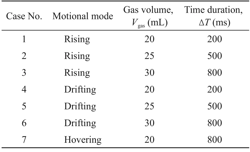
Table 3 Experimental case table
Fig.5 presents the results of the rising mode with respect to the premixed gas amountsVgasand time durations ∆T.WhenVgas=20 mL and ∆T=200 ms(Figs.5a and 5b),the minirobots transiently jump up‐ward (within 10 ms) by combustion.Propeller thrust‐ers are automatically switched on at 200 ms,leading to a smooth rising motion.Afterward,the minirobots continue rising until they reach the water surface at 1630 ms.WhenVgas=25 mL and ∆T=500 ms (Figs.5c and 5d),the minirobots jump up with higher speed due to the increased premixed gas amount.The propellers are activated at 500 ms,and inconspicuous pauses are observed during the switching process.The miniro‐bots finally reach the water surface at 1700 ms,show‐ing a reduced actuation efficiency.WhenVgas=30 mL and ∆T=800 ms (Figs.5e and 5f),the minirobots jump up dramatically in 10 ms,and the propeller thrusters are switched on at 800 ms.Unlike in the former cases,the motions under this condition present obvious pauses during the switching process.Instead of im‐proving the kinematic performance,combustion has brought unsteadiness to the overall motions due to the excessive time duration (i.e.,∆T=800 ms).
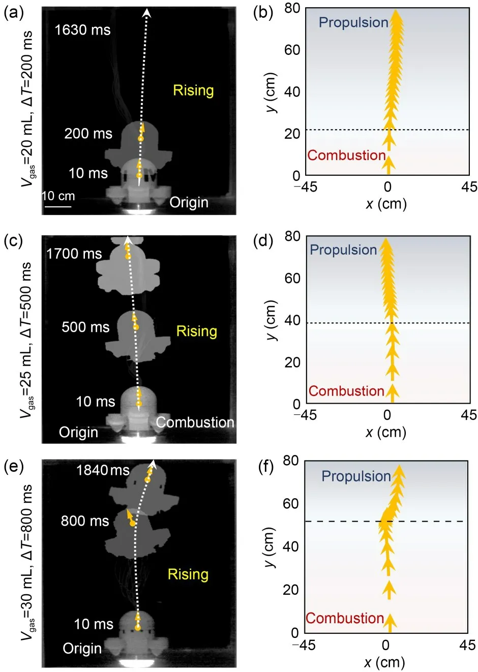
Fig.5 Experimental results of the HDM minirobots in the rising mode.Captured images (a,c,and e) and processed trace vectors (b,d,and f) showing the kinematic performance under the cases of Vgas=20 mL,ΔT=200 ms (a and b),Vgas=25 mL,ΔT=500 ms (c and d),and Vgas=30 mL,ΔT=800 ms(e and f)
Fig.6 presents the results of the drifting mode with respect to the premixed gas amountsVgasand time durations ∆T.WhenVgas=20 mL and ∆T=200 ms(Figs.6a and 6b),the propeller thrusters start working at 200 ms with differential speeds after jumping.The minirobots perform the rotation phenomenon to adjust their motional direction to horizontal.
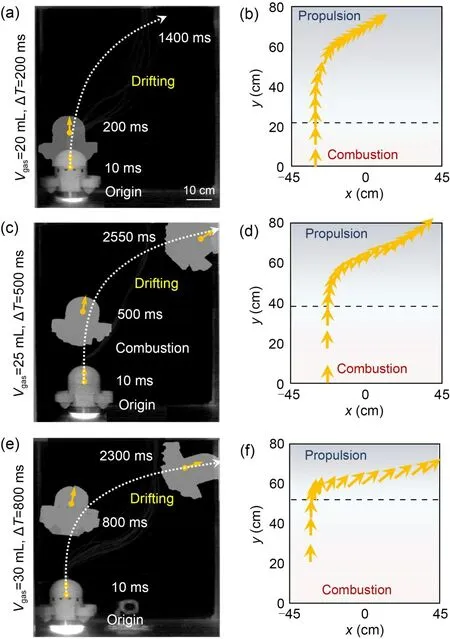
Fig.6 Experimental results of the HDM minirobots in the drifting mode.Captured images (a,c,and e) and processed trace vectors (b,d,and f) showing the kinematic performance under the cases of Vgas=20 mL,ΔT=200 ms (a and b),Vgas=25 mL,ΔT=500 ms (c and d),and Vgas=30 mL,ΔT=800 ms(e and f)
Due to the early activation of the propeller actua‐tion,the minirobots reach the water surface before the completion of the rotation process.WhenVgas=25 mL and ∆T=500 ms (Figs.6c and 6d),the propellers start working at 500 ms,adjusting the orientation of the minirobots until they reach the boundary at 2550 ms.WhenVgas=30 mL and ∆T=800 ms (Figs.6e and 6f),the minirobots jump up dramatically.The propeller thrusters are switched on to let them move horizontally.The trajectory of the minirobots can be adjusted by changing the premixed gas amount and time duration.
Fig.7 presents the results of the hovering mode.After the same combustion actuation process as the rising and drifting modes whenVgas=20 mL,the pro‐pulsion process is started at 800 ms to provide a lower thrust force,leading to a force equilibrium to maintain hovering.The experimental results showed that the HDM minirobots can achieve fast and flexible under‐water motion performance.
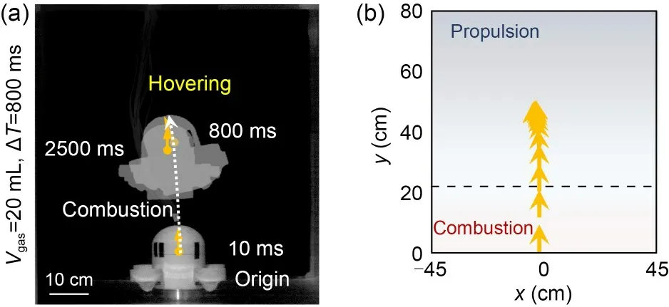
Fig.7 Experimental results of the HDM minirobots in the hovering mode.Captured images (a) and processed trace vectors (b) showing the kinematic performance under the case of Vgas=20 mL,ΔT=800 ms
In addition,we conducted experiments in a dy‐namic fluid environment to further verify the motion performance of the underwater minirobots.Fig.8a shows the flume setup.The flow velocityvwand input gas amount were set tovw=0.4 m/s,Vgas=20 mL,respectively.Fig.8b shows the testing process.The experimental results showed that the response time (~9 ms) and the actuation acceleration (~10 m/s2) of the robot in the dynamic fluid environment were consistent with those in a stationary pool (Wang et al.,2023).
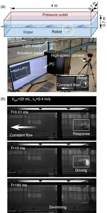
Fig.8 Experimental results of the minirobots in the dynamic fluid environment: (a) construction of the test platform setup;(b) captured images showing the kinematic performance under the case of Vgas=20 mL,vw=0.4 m/s
4 Model validation
4.1 Numerical modeling and results
The kinematic performance of the HDM miniro‐bots was numerically simulated in ANSYS Fluent(Adam et al.,2017),as shown in Fig.9a.The simula‐tion method is based on a fluid–solid coupling strategy that combines the mechanical analysis of a solid object (i.e.,minirobots) with the fluid dynamic analy‐sis of a disturbed flow field.Since the minirobots are undeformable,they can be simplified as a rigid object propelled by the combustion thrust force against the wall of the tank,which transiently disturbs the envi‐ronmental field.The spring and remeshing methods were selected to ensure calculation accuracy,i.e.,the mesh was given deformation tolerances and the global mesh was remeshed when the deformation exceeded the tolerances,respectively.Table 4 presents the de‐tailed parameters of the numerical model and Table 5 the case table of the numerical simulation.The kinematic performance calculated by the developed numerical models is shown in Fig.9b.Further results are given in Videos S4–S6 of the ESM.
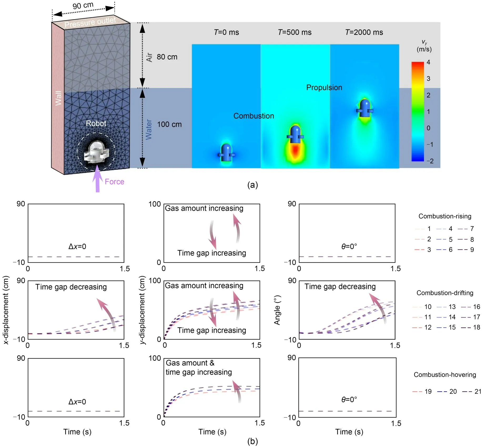
Fig.9 Numerical modeling of the underwater minirobots actuated by HDM: (a) setup of the numerical models and the simulated motions of the minirobots in the rising mode;(b) numerical results of the minirobots in the rising,drifting,and hovering modes.vy is the velocity of the robot in the vertical direction.References to color refer to the online version of this figure
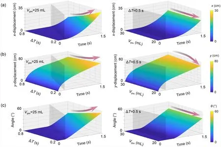
Fig.10 Theoretical results in the condition of drifting mode (Vgas=25 mL,ΔT=0.5 s): (a) horizontal displacements;(b) vertical displacements;(c) deflection angles.References to color refer to the online version of this figure
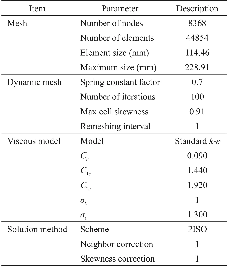
Table 4 Parameters used in the numerical simulations
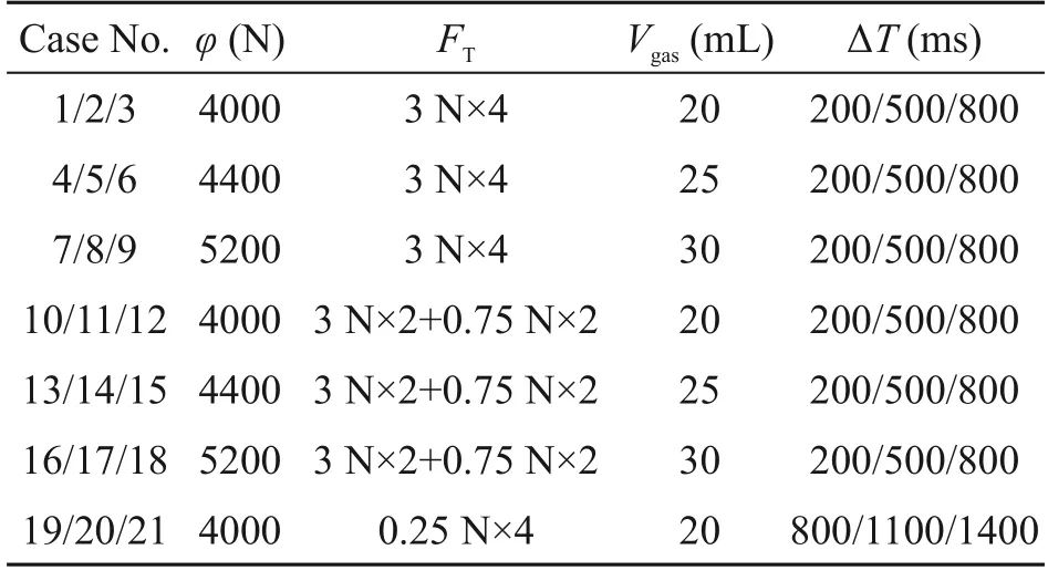
Table 5 Numerical case table
In the rising mode,the minirobots jump upward rapidly duringT=0–200 ms,actuated by explosive thrust forces generated by combustion.DuringT=200–1500 ms,the velocity of the minirobots is signifi‐cantly reduced due to drag.The displacements in they-direction are increased with the increment ofVgasand decreased with the increment of ∆T.However,the displacements in thex-direction and deflection angles are ideally calculated as constants (i.e.,0 mm and 0°).In the drifting mode,thex-direction displacementsand deflection angles are independent ofVgas,and are increased and decreased,respectively,with the incre‐ment of ∆T.In the hovering mode,the hovering state is directly determined byVgas.To reach the hover state,onceVgasis selected,∆Tis correspondingly determined.
4.2 Theoretical modelling and results
A theoretical analysis model of motion process of the HDM minirobots was developed.The driving process can be divided into three stages,i.e.,the com‐bustion process,deceleration process,and propulsion process.In the combustion process,the force equilib‐rium can be shown as
whereFC,G,FB,FD,FR,andFAare the thrust force generated by combustion,gravity of the minirobot,buoyancy of the robot,drag force,resultant force,and added mass,respectively.λ1is the end time of the combustion process.FCcan be calculated as (Yang et al.,2020;Wang et al.,2021)
φis presented in Table 5.FDcan be calculated as
whereCd,ρwater,S,andvare the drag coefficient,water density,upstreaming area,and velocity of robot,re‐spectively.FAcan be calculated as
whereαis the added mass coefficient andVis the volume of the robot.The duration time of the com‐bustion process was 8.9 ms (Yang et al.,2020).The deceleration process can be described as
The end time of the deceleration processλ2can be calculated as
All the motion modes were distinguished by the propulsion process.In the rising and hovering modes,the propulsion process can be described as
Note that the difference between the rising and hovering modes is the value ofFT(Table 5).In the drifting mode,the motion in a 2D plane can be de‐scribed as
where the subscriptsxandyindicate the horizontal and vertical directions,respectively.
The kinematic performance of the HDM miniro‐bots can be theoretically obtained by solving Eqs.(1)–(8).Figs.10a and 10b illustrate the relationships be‐tween the premixed gas amount,time,activation time of the thrusters,and thex-displacement.During 0-1.5 s,the deflection angles,premixed gas amount,and actu‐ation time gap are compared between the two driv‐ing methods,which are ranged asx∈[0,35] cm,y∈[0,80] cm,θ∈[0°,60°],Vgas∈[20,30] mL,ΔT∈[0.2,0.8] s,respectively.Depending on the propulsion du‐ration,thex-displacement and deflection angle are sig‐nificantly decreased when ∆Tis increased from 0.2 s to 0.8 s (Vgasis 25 mL).Thex-displacement and deflec‐tion angle are sustained asVgasis changed at ∆T=0.5 s,mainly due to the relationship between the rotation phe‐nomenon and the propellers’ thrust.They-displacement is increased asVgasis changed from 20 mL to 30 mL at ∆T=0.5 s,due to the dominant effect ofVgasony-displacement.
The HDM-driven minirobots reported in this study are characterized mainly by their underwater actuation performance,so this study focused mainly on the re‐sults from the test experiments.Since the numerical simulations and theoretical modelling were used only to validate the experimental results,the theoretical model may not be suitable for wider use.In a recent publication,we have developed a comprehensive the‐oretical model to analyze the actuation performance of HDM-driven minirobots (Yang et al.,2022).
4.3 Comparison and validation
The experimental,numerical,and theoretical re‐sults of the minirobots were compared (Fig.11).In particular,the motion positions at 1.5 s were compared under different premixed gas amountsVgasand time gaps ∆Tbetween combustion and propulsion.In the rising mode,the minirobots could be lifted by com‐bustion by an average of 76.8 cm and a maximum of 92.4 cm.In the drifting mode,they could be lifted by 63.2 cm with a maximum of 71.5 cm and drift later‐ally for an average of 23.1 cm and a maximum of 36.4 cm.In the hovering mode,they could be lifted and hover at a certain height for 44.8 cm with a maximum of 49.2 cm.Although the factors such as unstable com‐bustion and the center-of-gravity shift may slightly affect the accuracy of the experimental results,the overall differences among the comparisons in this study were only about 10%,which is acceptable.
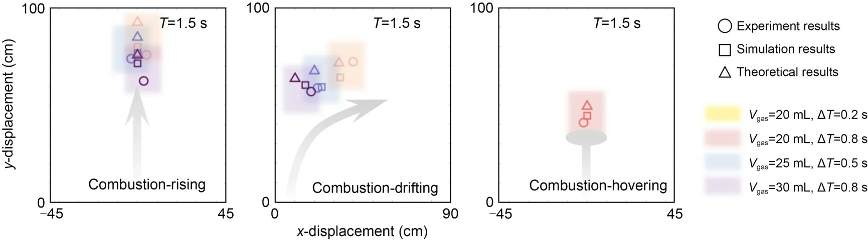
Fig.11 Comparison of the motion performance between the experimental,numerical,and theoretical results.The motion performance was investigated with respect to the gas amount and time gap between the rising,drifting,and hovering modes.References to color refer to the online version of this figure
5 Locomotion performance
Fig.12 summarizes and compares our proposed method with existing hybrid driving technologies enabled by combustion (Tolley et al.,2014a;Zi et al.,2016),SMP (Schmidt,2006;McCoul et al.,2017),magnets (Sadeghzadeh et al.,2012;Li et al.,2016;Chen et al.,2018),EM (Mohd Said et al.,2017;Tone and Suzuki,2018),gels (Shin et al.,2008;Yue et al.,2013;Zhang et al.,2013;Kadiyam and Mohan,2019;Gu et al.,2020),and thrusters (Stokes et al.,2014;Kim et al.,2017;Zhang et al.,2021).The HDM mini‐robots reported in this study performed with satisfactory operational reliability and transient actuation ability.Combustion-based actuation is able to address the chal‐lenges of instantaneous rapid starting,and the propellerbased actuation is able to address the challenges of motion performance.The drawbacks of previous propeller-based technologies are their longer actuation time and lower driving speed (Stokes et al.,2014;Kim et al.,2017;Zhang et al.,2021).The disadvantages of the published combustion driving methods are their rel‐atively low control accuracy due to the over-transient driving time and the discontinuous driving force(Tolley et al.,2014a;Zi et al.,2016).The HDM could be a potential solution to address the issues of both ac‐tuation methods by offering transient actuation and a sustained driving force.Fig.12 also compares the di‐mensions of the devices in those studies,which ranged from the millimeter to centimeter scales.In particular,the HDM minirobot bodies are about 30 mm high(Table 1).Increasing the overall size of HDM to the meter scale,the estimated combustion-based driving force would be 100 kN with an actuation velocity of 10 m/s,while the propeller-based driving force would be about 20 kN in total with a velocity of 3 m/s.As a consequence,the main contribution of our HDM method is the combination of combustion with propellers to achieve superior motion performance.
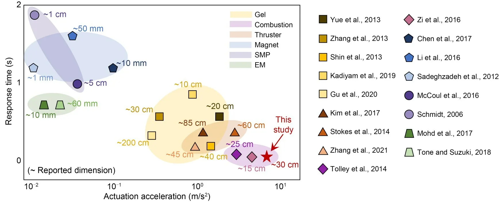
Fig.12 Comparison between the reported HDM and the selected driving technologies in previous studies,including gel,combustion,thruster,magnet,SMP,and EM.References to color refer to the online version of this figure
1.Rapidity in underwater motion.Traditional driving methods (e.g.,multi-propeller cooperative pro‐pulsion,hydraulic propulsion,vector propulsion,and waterjet propulsion) typically achieve~3 m/s2in actu‐ation acceleration and~0.2 s in response time.How‐ever,many applications require transient reactions (e.g.,underwater transient starting and braking,escaping from being stuck,instantaneous obstacle avoidance,and instantaneous steering).In our previous study,we reported the TDM actuated by combustion,which could achieve an actuation acceleration of~10 m/s2and a re‐sponse time of~0.01 s (Jiao et al.,2023).
2.Continuity in underwater motion.The TDM has severe limitations with continuous driving.However,many applications require continuous motion.Propeller thrusters make up for the deficiency of continuity in the TDM,providing a continuous and stable driving force.
3.Controllability in underwater motion.The HDM developed in this study combines conventional driving methods with TDM,i.e.,it combines combustion-based actuators with propeller thrusters to provide a promis‐ing powering technique for application to underwater robots in ocean engineering.The HDM-enabled under‐water minirobots can achieve accurate,fast,and flexi‐ble underwater locomotion performance.In the exper‐imental tests,the trajectory of the robot was within the preset parameter range.This class of HDM,compris‐ing hard and soft actuation functioning synergistically,is capable of performing tasks that neither can do alone.
6 Limitations and future work
Although the minirobots perform promisingly with HDMs in a hydrostatic environment,testing in real complex fluid environments has not been conducted,and there has been limited development of functional applications.As a follow-up study,the design and algo‐rithm of the underwater robots are now being optimized and will be tested in a field environment for further in‐dustrial applications.The combination of artificial in‐telligence (AI) with the new robot would allow deep learning to be applied to the design and use of robots.In addition,it is necessary to develop a variety of underwater operation functions for the robot,such as monitoring,human-robot interaction,target recogni‐tion,and grasping,to further expand the application prospects of robots in the field of engineering (Qi and Aliverti,2020;Qi et al.,2021).
7 Conclusions
In this study,we investigated the performance of underwater minirobots actuated by an HDM.The HDM minirobots,which are driven by actuations based on combustion and propellers,were investigated in rising,drifting,and hovering modes.Experiments were con‐ducted to test the kinematic performance of the mini‐robots in the three modes,and the test results indicated that the minirobots are able to transiently jump by combustion and then keep rising,steering or remain‐ing stable at a certain location in the three modes.Numerical models were developed to investigate the hydrodynamic-coupled mechanical process,and theo‐retical models were established to quantitatively study the mechanics of the driving process.Experimental,numerical,and theoretical results were compared,and showed satisfactory agreement.The motion perfor‐mance of the HDM minirobots (i.e.,acceleration and response time) was compared with that of existing hybrid actuation technologies.The results showed that the HDM minirobots have good operation reliability and transient actuation ability.Considering the charac‐teristics of transient velocity movement actuated by combustion,many application prospects (e.g.,under‐water transient starting and braking,escaping from being stuck,instantaneous obstacle avoidance,and instantaneous steering) in underwater scenarios could involve the use of these minirobots.Propeller thrust‐ers make up for the deficiencies of accuracy and ma‐neuverability in combustion,provide a continuous and stable driving force,and have potential applications,such as underwater monitoring in the potential appli‐cation scenario (Fig.13).The reported HDM combines the advantages of a transient response and underwater propellers to achieve more flexible and controllable motion performance,and represents a promising pow‐ering technique for application to underwater robots in ocean engineering.
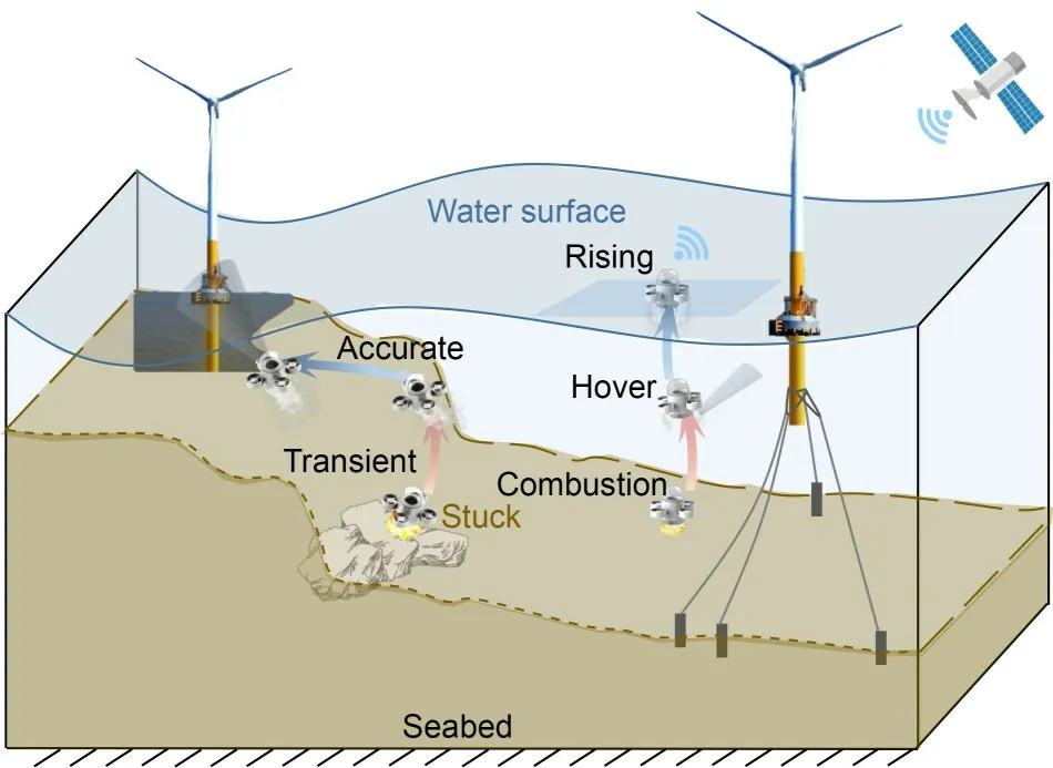
Fig.13 Potential applications of underwater minirobots actuated by HDMs
Acknowledgments
This study is supported by the Key Research and Devel‐opment Plan of Zhejiang Province,China (No.2021C03181),the Startup Fund of the Hundred Talents Program at the Zhejiang University,China,and the China Scholarship Council(No.202006320349).
Author contributions
Xinghong YE and Pengcheng JIAO designed the research.Lingwei LI and Xinghong YE conducted the experiments.Yang YANG proposed the theoretical model.Xinghong YE,Lingwei LI,and Yang YANG processed the numerical data.Xinghong YE and Yang YANG wrote the first draft of the manuscript.Zhiguo HE revised and edited the final version.
Conflict of interest
Xinghong YE,Yang YANG,Pengcheng JIAO,Zhiguo HE,and Lingwei LI declare that they have no conflict of interest.
 Journal of Zhejiang University-Science A(Applied Physics & Engineering)2023年7期
- Journal of Zhejiang University-Science A(Applied Physics & Engineering)的其它文章
- Numerical investigation of the effect of geosynthetic clay liner chemical incompatibility on flow and contaminant transport through a defective composite liner
- Monotonic uplift behavior of anchored pier foundations in soil overlying rock
- Fractal analysis of small-micro pores and estimation of permeability of loess using mercury intrusion porosimetry
- Square cavity flow driven by two mutually facing sliding walls
- Bogie active stability simulation and scale rig test based on frame lateral vibration control
- Analytical solution of ground-borne vibration due to a spatially periodic harmonic moving load in a tunnel embedded in layered soil