
Experimental Study on Flexural Behavior of Finger-Jointed Timber Beams Strengthened with CFRP Sheets*
2023-07-03 06:14WANGJianxingJIAYumengXUEMeihui
吉首大学学报(自然科学版) 2023年3期
WANG Jianxing,JIA Yumeng,XUE Meihui
(1.School of Civil Engineering,North China University of Technology,Beijing 100144,China;2.Chinese Academy of Science and Technology for Development,Beijing 100038,China)
Abstract:In order to improve the flexural strength of finger-jointed timber beams,three groups of timber beams were designed and manufactured.Through four-point compression test,the flexural performance of solid timber beams,finger-jointed timber beams and CFRP reinforced finger-joint beams were compared,and the influence of finger-jointed joints on the fracture mode of timber beams was analyzed.The displacement load curve of finger-jointed timber beams and the displacement load curve of finger-jointed timber beams were obtained,and the corresponding distinction was given for the failure characteristics of each type.Therefore,the feasibility of using CFRP to reinforce finger-joint is proposed.The test results show that the appearance of finger-joint has obvious influence on the bending failure process of timber.The appearance of finger-joint makes the fracture mode of timber change from ductile fracture to brittle fracture,and the flexural strength of finger-joint timber beam is significantly improved by using CFRP cloth reinforcement.
Key words:finger joint timber beam;fracture mode;flexural behavior;CFRP reinforcement
Glued timber,as a composite material,can enhance the mechanical properties of timber beams.In order to obtain any length of glued laminated timber,the timber beams are connected in the form of finger joints.Finger joint material is composed of several finger tenons arranged at different positions.Finger tenon can be regarded as a discontinuous point of timber,which will reduce the strength performance of finger-jointed timber[1].Therefore,in order to use and promote timber beams of various lengths,it is necessary to find appropriate ways to strengthen the finger-joint position of timber beams to improve the bending strength of finger-joint timber beams.
Carbon Fiber Reinforced Plastics (CFRP) is a carbon fiber reinforced carbon matrix composite,which is widely used in microelectronics,chemical,aerospace,biology,architecture and other fields.The mechanical properties of finger-joint of different timber types have been extensively studied in the previous literature.The strength of finger-joint depends on the interrelated factors such as the spreading speed of adhesive,assembly time and applied pressure during the gluing process[2].In addition,the weight,size structure and sheet thickness of the timber will affect the friction resistance of the finger-joint[3].Zhao et al[4]tested the dynamic elastic modulus of finger-joint specification materials by using the stress wave nondestructive testing method,and established the linear relationship between the dynamic elastic modulus and the bending strength.Feng et al[5]carried out bending test research on finger-jointed full-size laminated timber beams of different heights,and the results showed that the laminated timber beams have relatively stable bending bearing capacity and elastic modulus on the premise of ensuring the bonding quality,and their bending bearing capacity gradually decreases with the increase of beam height.Hao et al[1]conducted experiments on different species and adhesives and finger-joint between different species,and studied the strength properties and limit values of various species and adhesive finger-joint materials.He et al[6]and others studied the influence of joint position and quantity on the bending strength of finger joint.Stehr et al[7]studied the effect of adhesive penetration into cell cavity and adhesive diffusion into timber cell wall on surface roughness and strength of finger-joint.Zhou et al[8]studied the influence of section size,loading mode and finger-joint form on the bending resistance of large-diameter structural finger-joint,and the results showed that larch structural finger-joint can be fully used as timber engineering materials,and the wide-face bearing,V-shaped finger-joint and appropriate section size are conducive to ensuring the bending resistance of structural finger-joint.
Scholars at home and abroad have made certain achievements in the study of the bending resistance of finger-jointed timber beams.With the development of timber structures in China towards the direction of large span,the requirements for the mechanical properties of finger-jointed joints are also increasing.Finger joint can extend the length of solid timber beam,but as a discontinuous point in the timber beam,it will reduce the mechanical properties of the timber beam[9],so it is necessary to strengthen the finger joint.To solve this problem,this paper designs three groups of timber beams of equal length,height and width,and carries out bending strength tests on them,and then analyzes the impact of finger-joint on the bending strength and failure mode of the timber beam,and the effect of strengthening the finger-joint timber beam with CFRP cloth on improving the bending strength.
1 Design of Verification Test
The glued timber beams with larch as the base material were selected for the test,and three groups of 6 test timber beams were made according to the Integrated Timber for Structure (GB/T26899-2011)[10]and the Standard for Test Methods of Timber Structures (GB/T50329-2012)[11].When the height-span ratio of the test piece is not greater than 1/18,the effect of shear force on the deformation of the test piece can be ignored[9].Based on the actual project,this test comprehensively considers the material sampling,laboratory equipment and relevant test standards,and adopts the scale model.The test loading method is four-point compression test.The loading device is shown in Fig. 1 for the strain gauge measuring point arrangement of each group of test beams and the size of the test piece after planning.A total of five strain gauges are pasted on a single timber beam,with the gauge specification of 100 mm×3 mm,distributed in the fifth order along the height of the timber,with the marks from 1 to 5 from the bottom to the top.The shape and size of the finger-joint of the finger-joint timber beam are shown in Fig. 2.A total of 5 strain gauges are pasted on a single timber beam,with the labels from 1 to 5 from the bottom to the top.The samples were adjusted at 20 ℃ and 65% relative humidity,and the average moisture content (MC) of timber samples was 11.7%.The average density of this batch of timber is 406 kg/m3.Because the timber will be widely dispersed in practice,two identical reinforcement test pieces are specially made for the reference beam and the reinforcement beam.The physical and mechanical properties of each batch of timber are shown in Table 1,and the mechanical properties of the reinforcement material are shown in Table 2.The Young's modulus of the structural adhesive is 12.8 GPa,and the tensile strength is 32.7 MPa.
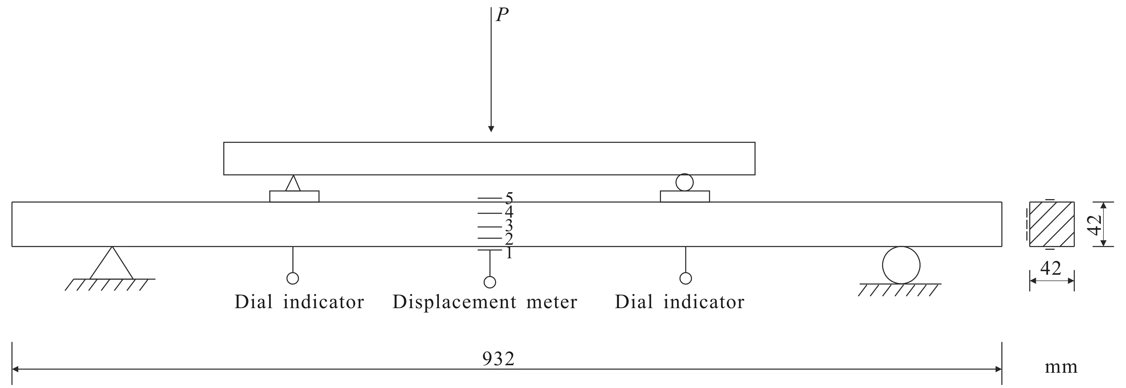
Fig. 1 Loading Device for Four Point Compression Test
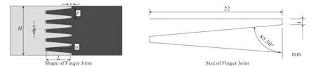
Fig. 2 Design Finger Shape

Table 1 Physical and Mechanical Properties of Timber

Table 2 Mechanical Property Index of Reinforcement Material
The test timber beams are divided into three groups,and the test timber beams are classified and numbered respectively.The research objects are mainly divided into three types:single timber whole beam,single timber finger-jointed timber beam with finger interface and single timber finger-jointed timber beam reinforced with CFRP.The specific classification and numbering of the timber test methods are shown in Table 3.

Table 3 Specific Classification and Number of Test Methods

Table 3(Continued)
2 Test Phenomenon and Failure Mode
There are obvious differences in the failure patterns of the three groups of timber beams.The failure of the single timber beam shows a certain ductility,while the failure of the finger-jointed timber beam becomes a sudden brittle failure due to the appearance of the finger-jointed joints.The strengthened finger-jointed timber beam has a longer failure process due to the reinforcement of CFRP cloth,showing a certain plastic tendency.
For the single timber beam specimen A1,at the initial stage of loading,the displacement gradually increased,and no other phenomenon occurred.When the load is loaded to 4.8 kN,the timber makes a slight sound without any other phenomenon.When loaded to 6.2 kN,the timber makes a slight noise and the timber beam begins to reach the yield period.When the load is 6.29 kN,small cracks occur at the extension of the bottom of the timber beam.The timber on the tension surface of the loading point at the bottom of the timber beam began to break.When the load was 7.29 kN,the timber beam broke,as shown in Fig. 3(a).Single timber beam specimen A2 is basically in linear elastic state during the loading process.When the load reaches 6.1 kN,the timber beam begins to crack,and then the crack continues but the volume is small.When the load reaches 7.3 kN,a series of sounds appear inside the test piece,and the deformation is obvious.When the load continues to 7.8 kN,the timber beam breaks.

Fig. 3 Failure Mode of Timber Beams
The failure pattern of the finger-jointed timber beam specimen is shown in Fig. 3(b).At the initial stage of the test loading,the specimen B1 and B2 began to emit intermittent crackling sound with the gradual increase of the load,but no cracks began to appear.At this time,the applied load was 3.7 kN and 3.8 kN respectively,and no visible damage was observed on the timber beam.With the continuous loading and fracture,a loud noise was suddenly made and the specimen was damaged.When damaged,the midspan displacement is 14.9 mm and 14.2 mm respectively,the support settlement is very small,and the test piece is not completely broken.The whole failure process is very short,which is sudden brittle failure.
At the beginning of loading,there is no obvious phenomenon in the reinforced finger-joint timber beam C1.When it is loaded to 3.3 kN,it makes a faint sound.With the strengthening of the load,the sound emitted by the test piece increases when it is loaded to 4.1 kN,and then returns to a small sound.When the load reaches 6.1 kN,there is a significant deflection in the middle of the timber beam span.At this time,the sound emitted by the timber beam increases and is more frequent than before.When the load reaches 6.8 kN,the sound increases again,and the stress is concentrated.Then the fiber cloth is also damaged and torn by tension,and the test piece is completely broken.In the case of damage,the settlement of the support of the reinforced finger-joint timber beams is small,the failure process is longer than before,the failure is sudden and obvious,the displacement load curve is not steep straight line,and there is a slight plastic tendency,which can be seen that the appearance of CFRP has changed the form of finger-jointed failure.At the initial stage of loading the C2 specimen,the timber beam has no other phenomenon except the initial deflection increase.During the process of loading to 5 kN,it can be observed that the deflection of the timber beam increases significantly.WhenP=5.4 kN,it makes a loud noise,but at this time,the external part of the timber beam is not obviously cracked.WhenP=5.9 kN,the timber breaks,and the mid-span displacement is about 29.3 mm.As shown in Fig. 3(c),the CFRP reinforcement improves the ultimate bearing capacity of the tensile zone of the finger-jointed timber beam.Compared with the unreinforced finger-jointed material,the slip of the lower finger-jointed part is more obvious.From the position of the crack,the section of the compression zone is relatively neat.
3 Analysis of Influencing Factors
3.1 Analysis of Test Results
When the finger joint is damaged,the lower part of the finger joint will slide out of the root of the tooth groove,and the upper part will be broken in a small area.The failure process of this part is mainly elastic deformation stage.In the elastic deformation stage,the displacement is positively related to the bending load,and the displacement increases with the increase of the bending load.For the finger joint beam,the first place damaged in the bending load-bearing process of timber is at the midspan,surface node and crack of the specimen.The materials of these parts determine the overall load-bearing capacity and the whole failure process of the specimen,and the fracture width is large,so the fracture location is difficult to predict.The finger joint specimens with qualified bonding quality are all damaged at the root of the finger joint,and no fracture is found at other parts.
The specimens of CFRP reinforced finger-joint timber beams with qualified bonding quality were also damaged at the finger joint,but compared with the specimens of unreinforced finger beam,the finger teeth of the damaged node slipped less from the root of the tooth groove,and the fracture area of the upper part also increased.The bending load-strain curve of the finger joint also shows a transition region from linear change.It also shows that finger joint has a significant effect on the bending failure process of timber.From the load strain curves of the three test beams,it can be seen that in one stage of initial loading,the test beam is basically in a linear elastic state,and the load changes linearly with the mid span deflection.With the increase of load,the deformation increases gradually,the stiffness of the beam decreases slightly,and the curve has a slight turning point.As the load continues to increase,the sound of beam fracture becomes larger,and the deformation continues to increase until the timber beam is damaged.
3.2 Analysis of Load-Midspan Deflection Relationship
According to the test results,it can be seen that the most important parts of timber bending failure are the compression point and the bending convex surface at the center of the span.For single timber beam,the failure stage is mainly divided into elastic deformation stage and viscoelastic deformation stage.The appearance of finger joint changes the bending failure track of timber.In the elastic deformation stage,the bending load is positively correlated with the mid-span displacement,and the load-strain curve of the unreinforced finger-jointed timber beam changes linearly until it breaks.The existence of finger-joint makes the whole failure process of timber beams change from elastic deformation stage and viscoelastic deformation stage to a single elastic deformation stage.
According to the applied load and the strain shown by the corresponding five strain gauges,the load-strain curves in Fig. 4 and Fig. 5 can be obtained. Comparison of Fig. 4 with Fig. 5,in the initial stage,shows that the two types of timber beams are basically in the linear elastic stage.Compared with the unreinforced finger-jointed timber beams,due to the participation of CFRP,the load-strain curve of the reinforced finger-joint timber beams appears a small plastic stage with the continuous increase of the load,but the failure mode is still brittle failure.The reason is that the corresponding fracture mode is also changed to brittle failure due to the simulation of timber damage at the finger-joint.Under the action of CFRP,the anti-slip ability of the finger-joint leads to the improvement of the tensile performance of the timber beam,which can withstand greater displacement.
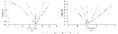
Fig. 4 Load-Strain Curve of Finger-Jointed Timber Beam
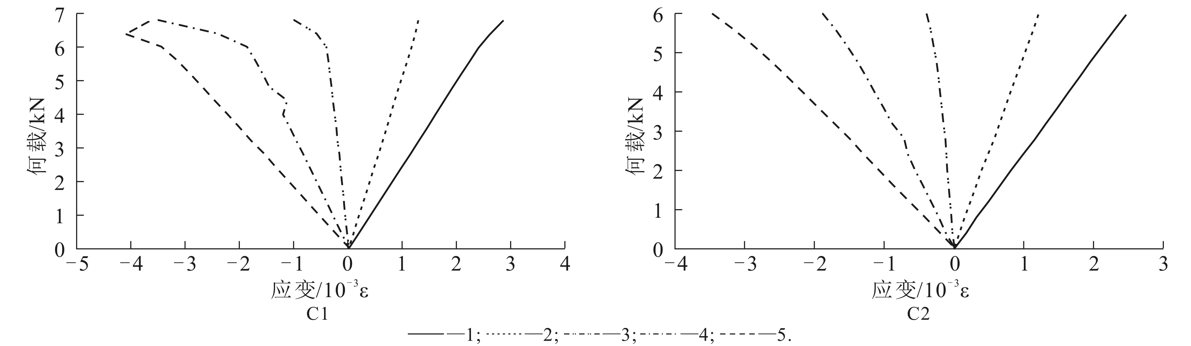
Fig. 5 Load Strain Curve of Finger-Jointed Timber Beams Strengthened with CFRP
4 Conclusion
(1) The appearance of finger joint changes the bending failure path of timber,which has a significant impact on the bending failure process of timber.Finger joint changes the bending failure path of timber,making the fracture mode of timber change from ductile fracture to brittle fracture.
(2) The strengthening of finger joint by CFRP makes the finger joint timber beam can withstand large deformation.In the test,the average midspan displacement of the unreinforced finger beam is 14.9 mm,and the average midspan displacement of the reinforced finger-joint timber beams is 28.1 mm,with an increase of 89%.The deformation performance of the reinforced finger-joint timber beams has been significantly improved.
(3) In the test,the average ultimate bearing capacity of the unreinforced finger beam is 3.65 kN,which is far less than the average ultimate bearing capacity of the unreinforced solid timber beam.After being reinforced with CFRP carbon fiber cloth,the average ultimate bearing capacity of the finger beam is 6.45 kN,which is close to the average ultimate bearing capacity of the unreinforced solid timber beam,with an increase of 70%.
From the results,the finger joint is the weak point of the mechanical performance of the finger timber beam.The addition of CFRP sheets has improved the deformation capacity and ultimate bearing capacity of the finger timber beam to a certain extent.The use of CFRP sheets to strengthen the finger timber beam in practical projects has strong application value.
